Radar, TV and Cellular Bands: Which Spectrum
Access Techniques for Which Bands?
Francisco Paisana,
Student Member
, IEEE, Nicola Marchetti,
Member
, IEEE, and
Luiz A. DaSilva,
Senior Member
, IEEE
Abstract—Opportunistic access has been considered by regu-lators for a number of different spectrum bands. In this paper, we discuss and qualitatively evaluate techniques used in the discovery of spectrum opportunities, also called white spaces, in the radar, TV, and cellular bands. These techniques include spectrum sensing, cooperative spectrum sensing, geolocation databases, and the use of beacons. We make the case that each of the three bands considered calls for a different set of spectrum access techniques. While TV bands are well matched to the adoption of geolocation databases, a database-assisted spectrum sensing mechanism may represent the most efficient solution to exploit the spectrum holes in radar bands. We drew this conclusion based on a multitude of factors, such as the radar antennas’ constant motion, and the absence of a hidden node problems in these bands. The unpredictability of cellular systems, on the other hand, calls for a more coordinated spectrum access approach, namely beacon signaling, that could be implemented using the already established cellular infrastructure and spare bits of its logical channels.
Index Terms—Cognitive radio; spectrum sensing; geolocation database; beacon signaling; radar bands; TV White Spaces; cellular bands.
I. INTRODUCTION
A
COGNITIVE Radio (CR) is an intelligent wireless communication system capable of gathering knowledge of its radio environment, which it then uses to increase its communication channel reliability and to dynamically access underutilized spectrum resources. Opportunistic Spectrum Ac-cess (OSA) is currently one of the main applications of CR. In one of its many forms, OSA can be viewed as a new spectrum sharing paradigm that allows secondary users (SU) to opportunistically access spectrum holes, called white spaces (WS), in the bands for which the primary users (PUs) hold a license. Another form of dynamic spectrum access being currently discussed by regulators is Licensed Shared Access (LSA). The idea consists in authorizing the negotiation and sharing of spectrum resources between incumbents and a limited number of LSA licensees [1]. As it provides a large amount of control to spectrum license holders, the concept is appealing for incumbents such as mobile network operators (MNOs).Although CR systems can be envisaged in any part of the radio spectrum, the frequency range considered more
Manuscript received March 25, 2013; revised August 22, 2013 and Decem-ber 30, 2013.
The authors are with Trinity College Dublin, Ireland (e-mail: [email protected]).
Digital Object Identifier 10.1109/SURV.2014.031914.00078
appropriate for their implementation is located between 100 MHz and 10 GHz. This includes the 300-3000 MHz range that the UK’s Office of Communications (OFCOM) has dubbed the sweet spot for spectrum sharing [2]. Frequencies below 100 MHz present several challenges, including long-range interference caused by ionospheric effects and prohibitively large antenna sizes, as a consequence of the large wave-lengths. Furthermore, the bandwidth provided is not large enough to make spectrum sharing economically attractive. As frequencies go beyond 10 GHz, advanced CR technology and spectrum sharing techniques become less appealing once again. At these frequencies, spectrum scarcity ceases to be a major issue due to not only the wide bandwidths available, but also the high atmospheric, rain, wall penetration and free-space losses, which provide extra spatial isolation to wireless communications and, consequently, allow greater frequency re-use.
For a specific secondary system, a spectrum resource is considered a WS if its utilization will not cause enough interference on incumbent communication systems to disrupt their communications at a given target performance level. Hence, WS availability must be assessed based on several operational, propagation and geographic parameters, namely systems’ coverage area, occupied bandwidth, sensitivity to interference, adjacent channel filtering, center frequency, user location and density and the type of propagation environment (indoor/outdoor and urban/rural). The four main spectrum access (SA) techniques proposed in the literature for the identi-fication of WSs are Spectrum Sensing (SS), Cooperative Spec-trum Sensing (CSS), Geolocation Databases (GL-DB) and Beacon Signaling [3]. Spectrum sensing targets the detection of primary systems’ activity during their regular operation. Its attractiveness lies in its simplicity, high flexibility, and low infrastructure requirements; one of its disadvantages is the inability to detect passive receivers, typically found in one-way communication systems, such as TV and wireless microphones. Cooperative spectrum sensing tackles the latter problem by allowing multiple CR devices to share their sens-ing results, which are then used to reach a conclusion about the presence/absence of a PU in a certain region and channel. In the GL-DB technique, each CR device estimates its position through GPS or another localization mechanism and queries a database for the nearby licensed channels’ availability. Beacon signaling is a technique where the incumbent devices cooperate with SUs by informing them about the spectrum resources that are being utilized. Hybrid schemes such as
DB+SS are also attractive solutions, as they can overcome the limitations of each individual technique.
In May 2004, the FCC announced the TV White Space (TVWS) initiative, aiming at the opening of this part of the radio spectrum for unlicensed secondary use [4]. It was initially defined that the TV Band Devices (TVBD) must support spectrum sensing and geolocation, coupled with access to a database to ensure the protection of both TV and wireless microphone incumbent systems. Eventually, concerns with spectrum sensing viability made the FCC drop this require-ment in 2010 [5]. These regulatory decisions have prompted discussion about the role of each different SA technique on the bands expected to be made available for opportunistic use in the future. To help answer this question, this paper analyses the adequacy of spectrum sensing, cooperative sensing, geolo-cation database and beacon signaling in three sets of bands: TV, cellular and radar. We chose the TV, radar, and cellular bands based on the economic attractiveness and diversity of technical challenges associated with their opportunistic use. To more clearly illustrate and compare the potential for the deployment of each specific spectrum access technique in each frequency band, we employ a coloring evaluation scheme where red, yellow and green indicate severe, moderate and low requirements, respectively.
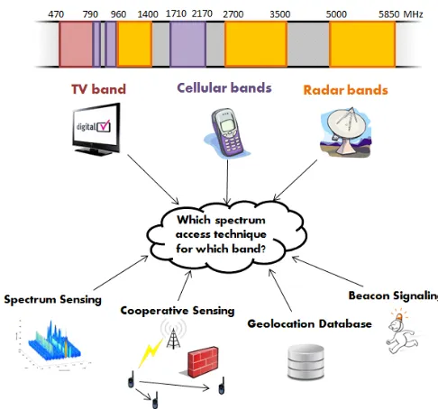
While a large number of articles and reports concerning CR technology deployment have been published, its great majority is solely focused on the TVWS case [5]–[10]. Looking at the literature that goes beyond this particular scenario, we highlight the articles on PU exclusion zone size estimation [11]–[14], the spectrum occupancy measurement campaigns [15], [16], and the EU FP7 QUASAR project [17]–[20]. In these studies, the economic value for opportunistic use of several licensed bands is assessed, based on their occupancy and on the main characteristics of their incumbents. None of these works, however, focus on the actual implementation of each SA technique in the analysed contexts. In contrast, the au-thors in [21] address the intricacies of the GL-DB deployment in several distinct use cases. This study, however, is limited to one SA technique, and its discussion is centred on how the GL-DB architecture features may need to be adapted to accommodate different wireless applications, without focusing on any specific band other than the TV band. With respect to the previous works, the contribution of this paper, whose scope is illustrated in Figure 1, is to assess how CR technology deployment may need to be adapted to tackle the different technical challenges that the three analysed spectrum bands pose.
[image:2.612.323.566.55.282.2]In Section II, we assess the main radio environment and incumbent systems’ characteristics and the challenges they pose to CR devices. In Section III, we briefly describe the four main spectrum access techniques used for WS detection, highlighting the main aspects of their implementation and how these aspects vary with the radio environment in which a CR device operates. In sections IV, V, and VI, we conduct a qualitative assessment of the viability of each of these tech-niques for three different radio bands, considering the primary systems each band accommodates. In order to corroborate some of the affirmations made in section IV regarding the use of a hybrid database-aided sensing technique for radar
Fig. 1. Illustrative view of the article’s scope.
bands, we provide in section VII a brief description and quantitative analysis of the performance of this technique. The main conclusions are drawn in Section VIII.
II. RADIOENVIRONMENTALFACTORS
Depending on the scenario where OSA is applied, SS, coop-erative sensing, GL-DB and beacon signaling techniques will have different specifications and requirements. For instance, the number of operations a GL-DB has to perform per second to be kept up-to-date will depend on the number of existing PU devices and how frequently their operating parameters change. SS complexity and detection times, on the other hand, will be related to the duty cycle of primary systems’ transmissions and how easily their signals can be distinguished from noise. This section provides a list of the incumbent-dependent radio environmental (RE) factors considered relevant for defining the specifications of each SA technique:
a) Uncertainty in PUs’ parameters – SA techniques
re-quire a certain amount of a priori knowledge about PUs’ characteristics or whereabouts to ensure their protection against harmful interference. However, some of this in-formation might not be always available, making the deployment of OSA a challenging task.
b) Diversity of incumbent systems– There is not a single
beacon signaling, geolocation database or spectrum sens-ing mechanism capable of protectsens-ing all types of incum-bent systems. In general, the spectrum access techniques’ specifications need to match the characteristics each type of primary system displays. This can be especially difficult to implement in bands where several distinct primary communication technologies coexist at the same time.
c) Number of devices– The greater the number of
a relevant factor to determine whether it is economically viable to make alterations in their infrastructure.
d) Planning – SA techniques, namely geolocation
databases, that do not check channel availability in real time are not able to avoid causing interference to licensed users, unless the incumbent systems’ operation is planned and known in advance.
e) Time dynamics and unpredictability– The more
unpre-dictable and dynamic the spectrum utilization by PUs, the more frequently CRs have to check channel availability.
f) Mobility – Incumbents’ mobility contributes to the
un-predictability of spectrum occupancy from the CR’s point of view and is usually countered by applying more frequent channel availability checks or by increasing the size of PUs’ exclusion zones (e.g. error regions [22]). Incumbents’ mobility will, therefore, increase the complexity and energy consumption of CRs and reduce the efficiency of spatial spectrum sharing. In particular cases, the PU and SU mobility can benefit local spec-trum sensing as it creates spatial diversity between the individual observations taken by a CR over time [23].
g) Duty cycle (DC) – The longer and more frequent the
PUs’ transmissions, the shorter the required sensing times and the lower the amount of available temporal spectrum opportunities.
h) Resilience/Safety Margin (SM) – This factor defines
how much interference a PU should handle from unli-censed devices. It is, therefore, related to the robustness of incumbents to interference, the amount of interference caused by other PUs and the fact that some incumbent communications may concern safety-of-life operations. i) Susceptibility to fading– A wireless signal is subject to
multiple propagation phenomena, such as obstructions, reflections, diffractions, scattering, and refractions, that affect its power and shape, before reaching the receiver. The inability of a CR to accurately quantify the impact of all these factors limits its knowledge about the radio environment, and, consequently, its capacity to discern spectrum opportunities. In general, this issue is only overcome by employing more conservative incumbent exclusion zone sizes at the GL-DB or through more con-servative detection thresholds when performing sensing.
j) Hidden receiver – CRs are only allowed to operate
in licensed spectrum bands provided their transmission does not increase the interference at primary receivers beyond a certain maximum tolerable interference level [24]. However, this level is difficult to quantify by the SU in the presence of passive nodes or hidden receivers in the primary network, which is the case of TV and wireless microphone systems in TVWS [10]. A common practice to counter this problem is to add a margin to spectrum access techniques’ detection thresholds or to increase the incumbent exclusion zones. The size of this margin will be proportional to the lack of knowledge the CR has about the position and antenna gain and orientation of the primary passive receivers.
k) PUs’ scale/range – Uncertainty is also found in the
derivation of the incumbents’ exclusion zones as a result of the limited spatial resolution of the SA techniques
em-ployed when compared to the scale or range of PUs (e.g. limited database grid resolution or sparse distribution of cooperative sensing nodes across the space).
l) Recognizable features/hidden periodicities –
When-ever PUs’ signals display recognizable features in their structure that make them easily distinguishable from noise, such as pilots, coding sequences or cyclic prefixes, less powerful sensing mechanisms can be adopted to determine channel availability.
m) UL/DL bands separation – The allocation of primary
systems uplink (UL) and downlink (DL) channels in separate frequency bands may influence CRs’ hardware and sensing specifications, in particular whether more than one RF transceiver and in-band sensing are required to keep track of PUs’ activity. Separate UL and DL bands also contribute to the loss of the reciprocity of the channel, since small-scale multipath affects the UL and DL differently, making sensing measurements less reliable, even in absence of hidden primary receivers.
n) Aggregate interference margin (AIM) – In order to
account for the combined effect of multiple devices’ interference, SA techniques may employ conservative propagation models or detection threshold values. This translates into the addition of a margin whose size will depend on the predominance of the aggregate interference in comparison to the interference caused by the closest secondary device to the primary receiver. In particular, this margin will be large for bands that accommodate primary systems of high coverage area, located at high altitudes, such as the ones employed in the satellite uplink bands. In cases spectrum sharing with SUs can be fully coordinated by PUs, the size of this margin may be set dynamically, improving sharing efficiency.
III. SPECTRUMACCESSTECHNIQUES
In this section, we provide a brief description of the main SA techniques, namely geolocation database, beacon signal-ing, spectrum sensing and cooperative senssignal-ing, proposed in the literature for the detection of WSs. We will then analyse how each of these techniques specifications will be affected by the RE factors we presented in the last section.
A. Spectrum Sensing
Local Spectrum Sensing is the SA technique that has received the most attention from the CR research community, due to its flexibility and the fact that it does not require any alterations to legacy systems or additional infrastructure. The ability to adapt in real time to changes in the radio environment, by periodically sensing the PUs’ channels during their normal operation, has been one of the most appealing arguments in favor of spectrum sensing, as it allows efficient exploitation of the temporal spectrum opportunities provided by licensed users in each band.
of different bands in which a CR operates increases, since it requires dedicated circuitry for each type of incumbent system. By contrast, ED is the simplest sensing scheme, does not require knowledge of the primary system and has optimal performance when signals are Gaussian. However, it is incapable of distinguishing interference from noise and its performance degrades rapidly when the noise power is not perfectly known. FD relies on the detection of the intrinsic periodicities embedded in modulated signals to distinguish them from Gaussian noise. However, it also requires knowing a priori the primary signal modulation scheme, and its complexity can sometimes become prohibitively high.
Spectrum Sensing Specifications:
a) Detection threshold – The detection threshold defines
the sensitivity the SU’s sensing algorithm should have to detect and avoid interfering with PUs. In the absence of hidden receivers, its value can be roughly deduced as shown in Appendix A. It depends not only on the ratio between transmit powers and bandwidths of PUs and SUs but also on several other factors, such as inter-PUs’ interference, inter-PUs’ resilience, multipath and the aggregation of interference of multiple CRs. Since the impact of these factors is not completely known to the CR, they are traditionally overcome through the addition of a conservative PU Interference Margin (PUIM), a Safety Margin (SM), a multipath margin (ΔMP), and an Aggregate Interference Margin (AIM), respectively, to the final threshold value. When some of the incumbent terminals are passive/hidden, the detection threshold must also include a hidden node margin (HNM) that accounts for shadow fading, misalignment of antennas, and re-ceiver location uncertainty for worst-case scenarios. For the TVWS, SS seems unable to efficiently tackle this problem with reasonable sensitivity levels [8] [25]. b) Sensing complexity– Intuitively, as the detection
thresh-old decreases, more complex sensing algorithms must be employed. There are, however, other important RE factors that affect the complexity and energy consumption of the sensing algorithm, such as the diversity of incumbents coexisting in the same band and the existence of clear, recognizable patterns in the PUs’ signal structure. As pointed out earlier, sensing algorithms should be designed to match each different radio environment scenario in order to be efficient at recovering WSs. If the incumbent signals are too distinct from one another or do not have any special, recognizable feature, the deployment of pow-erful sensing schemes such as matched filter or feature detection becomes challenging or even impossible.
c) Detection time/channel availability check time – The
channel availability check time (CACT) is the time it takes for a CR to detect the incumbent signal. Its value decreases with an increase in the detection threshold, with the incumbent signal’s duty cycle and with the performance of the sensing technique employed. The main consequences of spending more time performing sensing is the reduction of the CRs’ throughput in case of in-band sensing and an increase in power consumption.
d) Sensing periodicity– It defines how frequently sensing
must be performed in order for the SU to be fully up-dated about its radio environment space-time-frequency variations that result from multipath, shadowing, mobility and alterations in the incumbent systems’ operational parameters. Sensing periodicity should be high not only for CRs to adapt to dynamic scenarios but also to avoid causing long periods of interference on safety-critical systems. Like the sensing time requirement, an increase in sensing periodicity will reduce SUs’ throughput and increase their energy consumption.
e) In-band sensing – Hardware limitations and the
inter-ference generated by the on-going SU’s communication practically prevents the CR from performing sensing and transmitting/receiving data simultaneously in the same band. To address this issue, techniques such as quiet period (QP) scheduling, dynamic frequency hopping and self-signal suppression (SSS) are suggested in the liter-ature [26]. Depending on their duration and periodicity, QPs, in particular, may significantly decrease CR devices’ throughput and cause transmission interruptions. This problem is known as the sensing-throughput tradeoff [27]. With the separation of the incumbent uplink (UL) and incumbent downlink (DL) channel frequencies, however, in-band sensing might not be necessary. When frequency division duplexing (FDD) is adopted in a cellular net-work, for instance, a CR occupying the cellular UL band can check the presence of a Base Station (BS) nearby by (out-of-band) sensing the respective BS DL band. While this solves the sensing-throughput tradeoff, it also requires CRs to be equipped with two transceivers, which increases their complexity and power consumption.
f) Ability to recognize spatial spectrum opportunities
– This factor defines how efficiently spectrum sensing can exploit the spatial aspect of spectrum sharing in a certain band. In other words, it will measure the amount of spatial spectrum opportunities (SO) a CR device can recover through this SA technique. This quantity is directly related to the conservativeness of the detection threshold employed, in particular if a margin is applied to counter the aggregation of interference, the hidden receiver, fading, incumbents’ variable operational param-eters (e.g. transmission power, band, or target signal to interference plus noise ratio), or to protect safety-critical systems.
g) Ability to recognize temporal spectrum opportunities
– This factor is related to the ability of the CR to adapt in real time to the variations in the radio environment that surrounds it and, ultimately, to efficiently recover temporal WSs. It is, therefore, a consequence of the unpredictability and dynamicity of the radio environment, and of the sensitivity of the sensing techniques employed by the CR to these variations.
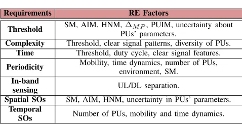
Table I summarizes the relation between the incumbent systems’ characteristics and the consequences they have on spectrum sensing specifications and requirements.
B. Cooperative Sensing
TABLE I
DEPENDENCY OF THESSSPECIFICATIONS ON THEPUS’ CHARACTERISTICS
Requirements RE Factors
Threshold SM, AIM, HNM,PUs’ parameters.ΔMP, PUIM, uncertainty about Complexity Threshold, clear signal patterns, diversity of PUs.
Time Threshold, duty cycle, clear signal features.
Periodicity Mobility, time dynamics, number of PUs,environment, SM.
In-band
sensing UL/DL separation.
Spatial SOs SM, AIM, HNM, uncertainty in PUs’ parameters.
Temporal
SOs Number of PUs, mobility and time dynamics.
affect a CR’s ability to detect spectrum holes through local sensing. The impact of these phenomena could, however, be mitigated if individual SS results were shared between CR devices at different positions and turned into a combined decision regarding the availability of a specific channel. This mechanism, called cooperative spectrum sensing (CSS), is illustrated in Figure 2. Based on local spectrum sensing techniques alone, the attenuation caused by walls or other obstructions leads CR1 to draw an erroneous conclusion (H0 -PU absent) about the presence of a primary transmitter (PTx) nearby. If, on the other hand, CR1 utilizes CR2’s sensing data, it will conclude that the channel is being occupied (H1) by a (hidden) PU. In addition to the contribution to the reduction of the hidden node effect, CSS may also decrease individual SUs’ sensing time.
The cooperative process of combining the local sensing results from different CR nodes is named data fusion [28]. Depending on the bandwidth and energy available, three different combining techniques can be employed: (i) soft combining; (ii) quantized soft combining; (iii) hard combining. Soft combining has the highest performance of the three, as CRs exchange sensing data that have not been subject to any type of quantization process. However, the high overhead it incurs without significant advantages over the alternatives has led its applicability to DSA to be questioned in the literature [29]. At the other end of the spectrum, hard combining has the lowest detection performance and overhead, since it is based on applying simple linear fusion rules (e.g. OR, AND and majority) that only take one-bit local decision information from each different cooperative CR as input.
[image:5.612.53.292.85.208.2]One of the main obstacles to CSS implementation has been the lack of performance guarantees it can provide, as its achievable detection level depends on the number of nodes involved in the cooperating process and on whether their individual samples are under the effect of spatially correlated shadowing [28]. CSS also adds significant overhead to CR networks for the exchange of the individual observations and often implies the use of a common control channel (CCC), not always a realistic assumption for DSA, considering the fact that this channel is also affected by PUs’ activity and the potential a single CCC has to become saturated and a single point-of-failure [30].
Fig. 2. Cooperative sensing between two CR devices where CR1 cannot detect the PTx (H0: PU absent) due to an obstruction in the propagation path.
Cooperative sensing specifications:
a) Cooperative gain – It refers to the improvement in
de-tection performance and relaxed sensitivity requirements obtained when individual spectrum sensing samples from different CR users are combined. It depends not only on the data fusion techniques employed and the number of cooperating nodes, but also on other radio environment features such as:
• Hidden receiver and susceptibility to fading – The
gains obtained through the spatial diversity provided by cooperative sensing will be particularly high in the presence of hidden receivers and when the effects of reflection, refraction, diffraction and scattering are con-siderable (e.g. urban environments, high frequencies and low antenna heights).
• Spatially correlated fading – The loss of spatial
diversity between CRs’ observations when blocked by the same obstacle can be detrimental to CSS [28]. The effect of this phenomenon is usually estimated based on the distance between cooperating SUs, the PUs’ range, and the type of environment [31]. In cases where the correlation between users’ observations is high (e.g. large-scale PUs), node selection mechanisms or fusion rules that predict how correlated different cooperating nodes’ samples are may need to be employed.
• PU and SU mobility– The spatial diversity between
the observations taken by a CR in high mobility scenarios increases local sensing performance and, therefore, decreases the cooperative gain. It was shown in [23] that at high speeds, it can be more efficient for a CR to sense individually multiple times than to cooperate with other users.
b) Density of SUs– The unambiguous detection and
protec-tion of short-range PUs through CSS may require a SU network with a prohibitively high density of cooperating nodes, especially in the case of urban scenarios [32] [33].
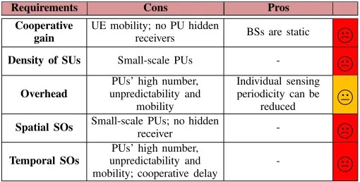
c) Overhead – Sharing sensing samples may result in an
Fig. 3. Increase of PUs’ exclusion zones from the SUs’ point of view when CSS is employed. Exclusion zones and white spaces are represented in orange and green color, respectively.
in scenarios with a large number of short-range PUs with high mobility and unpredictable behavior. Node selection and censoring are mentioned in the literature as possible techniques to increase the energy efficiency and minimize the traffic on the CCC in CRNs without significantly affecting CSS performance [28], [34], [35]. By using node selection, some CRs are allowed to enter sleep mode, which leads to lower sensing and transmission costs for the overall network. Censoring results in a reduction of transmission costs, as it dictates, based on relevance, whether CRs’ sensing observations should be sent to other nodes.
d) Identification of spatial spectrum opportunities– On
the one hand, CSS allows a more efficient exploitation of the spectrum in the spatial domain, as it contributes to a reduction of the hidden node margins and, consequently, the relaxation of the sensing sensitivity requirements. On the other hand, CSS may raise a new issue known as the exposed node problem, which leads to significant under-utilization of the spectrum, in cases where the cooperating SUs’ separation and PUs’ ranges are comparable [33]. This phenomenon is illustrated in Figure 3. The exchange of sensing information close to the boundaries of PUs’ exclusion zones can lead some SUs to erroneously as-sume that a channel is occupied and, therefore, reduce spatial sharing efficiency. The exposed node problem is a consequence of disregarding SUs’ spatial diversity during data fusion. Possible ways to overcome this issue are to employ soft combining, less conservative fusion rules or more advanced data fusion techniques that consider the location or the correlation between sensing samples of different cooperating SUs. For instance, in [36], the authors propose a spatial diversity-aware clustering and data fusion technique where the cooperating nodes are grouped together based on the correlation of their local decisions.
e) Identification of temporal spectrum opportunities –
No major differences when compared to SS except for the additional synchronization and sensing results reporting delays.
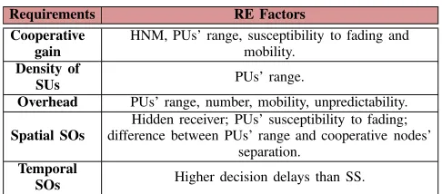
Table II describes the relation between the radio envi-ronment characteristics and the specifications of cooperative sensing.
TABLE II
DEPENDENCY OF THECSSSPECIFICATIONS ON THEPUS’ CHARACTERISTICS.
Requirements RE Factors
Cooperative gain
HNM, PUs’ range, susceptibility to fading and mobility.
Density of
SUs PUs’ range.
Overhead PUs’ range, number, mobility, unpredictability.
Spatial SOs
Hidden receiver; PUs’ susceptibility to fading; difference between PUs’ range and cooperative nodes’
separation.
Temporal
SOs Higher decision delays than SS.
C. Geolocation Database
In this spectrum access technique, a centralized database stores information about PUs’ spectrum use and position, which it then uses to draw conclusions regarding spectrum occupancy in each region. Secondary devices estimate their position using a localization technology such as GPS and report the resulting coordinates to the database. The database then replies with a map of the channels which are available for use, considering the querying device’s operating parameters and location [5], [8], [37], [38].
Distinctly from SS, GL-DB calculates the interference created between communication systems through theoretical propagation models rather than actual RF measurements. To avoid prohibitively high complexity, it first divides the terrain into squares with different latitude and longitude, each one representing a point or pixel on a geographical grid. Primary systems’ operating parameters, such as equivalent isotropic radiated power (EIRP), center frequency, bandwidth, antenna height, location and expected duration of channel usage, also stored in the database, are then used to draw the incumbent systems’ exclusion zones/keep-out regions, as shown in bur-gundy in Figure 4. The decision of whether a querying SU is authorized to transmit on a specific channel will depend on whether its coordinates are inside a grid pixel that belongs or is adjacent (to consider the inaccuracies of localization mechanisms, such as GPS) to one of these exclusion zones. The techniques used by a database to define WSs for SUs may significantly vary with the rules employed (e.g. FCC or ECC) [5], [37]. In [38], the authors compared the FCC and ECC approaches, demonstrating that the first was less protection-oriented, leading to increased throughput capacity for SUs.
Fig. 4. Channel availability by region/database pixel. The secondary device on the left is not allowed to transmit since it is inside the incumbent base station’s exclusion zone.
complexity and delays, but also the complexity and energy consumption that the frequent GL-DB consultation would pose to CRs. Next, we describe the main requirements of GL-DBs.
Geolocation Database specifications:
a) Registration of legacy systems – The GL-DB requires
a priori information about the incumbents’ position and parameters (e.g. EIRP, frequency and expected period of channel usage) to be able to check channel spatial and temporal availability. When this information is not available, which is the case for unregistered devices, this spectrum access technique is not feasible.
b) Complexity/processing power– One of the factors that
increase the implementation costs of a GL-DB is the number of terrain grid points it has to be able to update per second with information regarding the PUs’ spectrum occupancy. This is not only related to the grid resolution employed, but also to the mobility, traffic dynamics, number and range of PUs. Even for very static scenar-ios such as TVWS, the update of a TV base station’s exclusion zone with a radius of 150 km requires the computation of complex propagation models for millions of grid points (with a resolution of 100m x 100m). This issue is aggravated as higher grid resolutions start to be considered to accommodate short-range PU devices too. A GL-DB must also have the capability to answer a large number of SUs’ queries with the lowest delays possible in order to give timely information about the radio environ-ment and to avoid getting flooded. The impleenviron-mentation costs involved in providing this feature will increase as CR technology becomes more widespread.
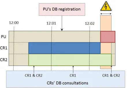
c) Consultation periodicity/maximum dissemination
de-lay – The CRs’ database consultation periodicity is set based on how far in advance incumbents’ spectrum utilization is planned. As illustrated in Figure 5, for instance, the protection of PUs that update their pa-rameters in the database at least 1 minute before their
Fig. 5. PU, CR1 and CR2 operation and GL-DB consultations and updates over time in a specific channel.
actual operation requires CR devices with a database consultation periodicity below or equal to 1 minute. Since CR2 only consults the GL-DB every 2 minutes, there is a period of time when it causes interference to the PU. For the cases where PUs or SUs are not static, or PUs have unplanned transmitting patterns, the GL-DB must be consulted frequently. This will lead to a significant increase in the SUs’ power consumption and GL-DB complexity, making its deployment unattractive from a business point of view.
d) Ability to recognize spatial spectrum opportunities–
As GL-DBs do not rely on direct, real-time measurements to define incumbents’ exclusion zones, they typically adopt conservative theoretical propagation models that seek to account for the impact of uncertain propaga-tion phenomena such as ducting, obstrucpropaga-tions, reflecpropaga-tions and scattering [31], the aggregation of interference, the unknown primary receiver location (hidden receiver), and that are able to provide extra protection to safety-critical systems. Incumbents’ exclusion zones must also account for database terrain grids with limited resolution or localization systems with limited accuracy, which can make this SA technique less adequate for the protection of small-scale PUs.
e) Ability to recognize temporal spectrum opportunities
– The major GL-DB drawback is its high update and information dissemination latencies, lacking the flexibil-ity to adapt to fast and unplanned variations in the radio environment. It is, therefore, expected that this method will not recover as many temporal spectrum opportunities as other SA techniques.
[image:7.612.51.298.56.242.2]Fig. 6. The radius of the incumbent’s exclusion zone (Rex) is equal to the radius of the exclusion zone in case the incumbent was static (R0ex) plus an error distance (Rerr).
The main aspects regarding the adoption of the GL-DB as an SA technique are summarized in Table III.
D. Beacon Signaling
In this spectrum sharing approach, primary licensed devices cooperate with secondary devices by transmitting information regarding their spectrum resources utilization through beacons. Although an attractive solution for efficient spectrum sharing, it raises several implementation issues, one of them being that its deployment usually requires significant changes to legacy systems’ infrastructure [8]. These changes are not only unattractive to incumbent users, but also infeasible to imple-ment when the technology is too widespread (e.g. cellular and WLAN). The lack of a global consensus on what band the beacons should use to transmit also represents a barrier to the deployment of this method in the near future.
Beacon information can be modulated through carrier tones or through direct sequence spreading codes. Although more complex, the latter is considered more reliable, as it usually inflicts less interference on licensed operation and it is not so easily mistaken for spurious signals or harmonics from other bands.
Beacon devices can be of four different types, depending on the entity that manages and emits their radio environment information [3]: per-transmitter, receiver, unlicensed, and area beacon. Throughout this work, special emphasis will be given to the receiver and area beacons, which have clear advantages when compared to the other two.
• Receiver beacon (RB) – This device is integrated in the
primary system receiver. Its main advantage comes from the fact it mitigates the hidden node problem.
• Area beacon (AB)– The area beacon is a dedicated radio
device that disseminates channel availability information, previously stored in a database, valid within a certain region. This method offers standardized access to GL-DB information without the need for CRs to directly query the database. It also makes the GL-DB less costly, more secure and less predisposed to jams and floods of queries, as it would only be accessed by the ABs, far less numerous than individual secondary devices. Nonetheless, the AB solution is still less dynamic than infrastructure-independent
TABLE III
DEPENDENCY OF THEGL-DBSPECIFICATIONS ON THEPUS’ CHARACTERISTICS.
Requirements RE Factors
Registration Uncertainty about PUs’ parameters.
Complexity PUs’ scale/range, number of PUs, time dynamics and
mobility and SU’s consultation periodicity.
Consulta-tion periodicity
PUs’ activity planning, mobility.
Spatial SOs PUs’ scale, susceptibility to fading, AIM, SM andHNM.
Temporal SOs
PUs’ activity planning, time dynamics and mobility and number of PUs.
spectrum access techniques, due to the update delays of the centralized database.
Beacon signaling specifications:
a) Design limitations– Beacons are communication devices
and, therefore, they must respect the regulations and poli-cies imposed for each radio band, including bandwidth and power limitations, and avoid causing interference to other PUs. Since there is not a universal beacon design capable of meeting these two requirements for all radio bands, these devices’ parameters and transmission channels must be defined based on the characteristics displayed by the PUs with which they co-exist.
b) Infrastructure costs – Contrarily to SS, this spectrum
access technique in general requires changes to the in-cumbent systems’ infrastructure. Therefore, its deploy-ment cost varies with the cost of each single beacon device and with the number of beacons that need to be installed to protect the PUs of a specific band from harmful interference.
c) Ability to recognize spatial spectrum opportunities–
The number of spatial opportunities recovered by a CR system is maximized when beacon devices are placed next to the primary receiver, avoiding the hidden node problem. Beacons may also carry additional data regard-ing PUs’ parameters, such as transmit power, bandwidth and maximum interference before service disruption, which assists SUs in defining a detection threshold. If completely integrated with the PU, the beacon can adjust in real time the information it transmits to SUs, avoiding issues related with aggregate interference and reducing the required safety margins.
d) Ability to recognize temporal spectrum opportunities
– In order to exploit the temporal aspect of spectrum sharing, the beacon devices may be only turned on slightly before and during PUs’ operation. This would ensure that CR devices detect primary systems far enough in advance and, as a result, do not cause any interference. Beacons may also carry data in their signal structure related to the expected period of utilization of the spectrum by the incumbent.
TABLE IV
DEPENDENCY OF THE BEACON SIGNALING SPECIFICATIONS ON THEPUS’ CHARACTERISTICS.
Requirements RE Factors
Design limitations
Regulations, PUs’ diversity, required dedicated channel for signaling.
Infrastructure
costs Number of PUs, beacon devices’ cost.
Spatial SO HNM, AIM and SM, depending on how and wherethe beacon device is deployed.
Temporal SO Beacons may emit information regarding PUs’
expected period of operation.
the conservativeness of the propagation models, and high update and information dissemination delays.
Table IV illustrates the relation between the radio environ-ment characteristics and the requireenviron-ments of beacon signaling. The next three sections present an analysis of the four techniques used to recognize spectrum opportunities, in the context of the radar, TV, and cellular bands.
IV. RADARBANDS
Radars are object detection systems with application in sev-eral areas such as aeronautical and maritime radionavigation, weather forecast and radiolocation. Although they occupy a significant portion of the international radio spectrum, their spectrum occupancy is usually under 5 % and does not vary significantly throughout a day [15]. For this reason, radar bands are nowadays seen as promising candidates for opportunistic access [39] [14].
The most adequate radar bands for secondary use are the L, S and C bands between 960-1400 MHz, 2.7-3.6 GHz and 5.0-5.850 GHz, respectively. These frequencies are sufficiently low to avoid high power consumption and the usage of highly directional antennas, and sufficiently high to offer considerable bandwidths when compared to VHF, for example. Furthermore, they are close to the cellular and ISM bands used for 2G/3G/4G and WiFi, respectively, facilitating the production of devices capable of using all these frequencies.
Several interference studies for the radar bands have already been conducted [13], [14], [19], [20]. In [14] both co-channel and adjacent channel interference generated by a single sec-ondary device are studied for the L, C and S bands. The author considers the C band to be the one with the best sharing conditions where, according to the tests, co-channel and adjacent channel coexistence is possible at a distance equal to or higher than 45 km and 17 km, respectively. In [19], the authors study the impact of aggregate interference from multiple, uniformly distributed devices on the meteorological radar band at 5.6 GHz. Their findings highlight the technical difficulties associated to the measurement of the aggregate interference on the PU, since its value hugely depends on the propagation environment and, in particular, the path loss exponent. This work was further extended in [20], where non-uniform user distribution scenarios were considered.
Spatial sharing is an attractive aspect of radar bands, due to the limited number and usually fixed and well known position of their incumbents. However, the radars’ high transmission power and heavy deployment in coastal regions and close to
airports can block a large percentage of the world population from accessing this spectrum. For this reason, other sharing scenarios have also been assessed in the literature [13], [17], [40], [41]. Let us take, as an example, primary radar systems with highly directional rotating antennas. From a temporal sharing perspective, a considerable amount of spectrum op-portunities can be exploited in this scenario by allowing CRs inside exclusion zones to transmit when the radar antenna’s main beam is pointing in another direction. However, this requires some kind of synchronization of the CRs with these antennas’ sweep patterns, which might be technically chal-lenging considering the diversity of incumbents operating in these bands and the fact that CRs may overhear signals from more than one radar station at the same time.
To provide a qualitative evaluation of the opportunities and challenges of DSA in radar bands, we start by discussing RE factors of particular relevance to these bands. We then consider how applicable each spectrum access technique is, given the operational characteristics of incumbent systems. We follow the same methodology when discussing each of the other bands analyzed in this article.
A. Radio Environmental Factors
a) Uncertainty in PUs’ parameters– Information
regard-ing radar stations’ position, EIRP, frequency and expected period of operation is usually available. Some military radiolocation information may, however, be classified.
b) Diversity of incumbent systems – Despite the same
operating principle, radar systems display very distinct features, dimensioned according to their application. Overall, radars can be classified as:
• Imaging / Non-imaging: Imaging radars form a picture or map, whereas non-imaging radars make a one-dimensional representation of the observed object or area;
• Primary / Secondary: In primary radar systems, the pic-ture of an object or area is formed using the echoes of the transmitted signal, while in secondary systems, it is formed through the two-way communication between an interrogator and a transponder;
• Monostatic / Bistatic: In monostatic primary systems, the transmitter and receiver are co-located, whereas in the bistatic case, they are separated.
From the waveform perspective, a radar signal can, in turn, be classified based on:
• Constant Wave (CW) / Pulse Radar (PR): CW radar signals are continuous in time, while PR signals are formed by a train of short pulses;
• Intrapulse Modulation (IPM): Pulses can be simple or compressed, for instance, through frequency modula-tion (FM) or phase modulamodula-tion (PM);
• Pulse Repetition Frequency (PRF): The PRF values of PR systems are generally around 1000 Hz for the S, C, and L bands. The PRF or pulse repetition interval (PRI) may not remain constant in some cases, e.g. in staggered and jittered PRF systems;
• Frequency agility: To avoid enemy jamming, a radar may hop from channel to channel in a pseudo-random manner.
Radar beams can be divided into two general types ac-cording to their shape: fan and pencil-shaped. Fan beams are characterized for being very wide in one direction and very narrow in the orthogonal direction, whereas pencil-shaped beams are directional in both elevation and azimuth. Radar scan patterns, that define the path the antenna beam takes to scan its environment, can be of several types, such as, circular, sector, raster, conical, helical, and spiral.
c) Number of devices – The number of radar systems
is generally low due to their long ranges, with heavier deployment close to coastal regions and airports.
d) Planning – Radar systems’ positions and parameters
tend to be planned ahead of time. There are, however, some exceptions, such as systems placed on airborne and shipborne platforms, which may not have pre-planned routes;
e) Time dynamics and unpredictability – Most radar
systems have fixed and predictable transmitting param-eters, such as transmit power, scan patterns, PRF, center frequency and position, for long periods of time. There are some exceptions, such as:
• Military radiolocation systems that employ frequency hopping techniques such as Electronic Counter-Countermeasures (ECCM) when subject to enemy jam-ming.
• Secondary radar transponders, whose emissions are not periodic and only occur after the reception of an inter-rogation message. CR devices might be able to predict these systems’ reply channel utilization by sensing activity in the respective interrogation channels.
• Some tracking systems that have irregular antenna scan patterns, designed to focus on specific targets.
f) Mobility – Some radar antennas are placed on mobile
platforms, such as ships and airplanes.
g) Duty cycle (DC) – Radar systems, with the exception
of CW systems, emit signals of very low duty cycles, which can be less than 0.1%, depending on the pulse width and PRF employed. The directional antennas and long rotation periods also contribute to the reduction of radar signals’ duty cycle, from the CR device’s point of view.
h) Resilience/Safety Margin (SM) – The importance of
radar systems to public safety significantly varies with their application. Aeronautical radionavigation systems (ARNS), in particular, are safety-of-life services, so ev-ery possible precaution must be taken to ensure their protection [18]. Nevertheless, radar systems also em-ploy interference mitigation techniques such as low duty cycle suppression techniques of asynchronous signals, Side Lobe Suppression (SLS), and Electronic Counter-Counter-Measures (ECCM). These mechanisms should be considered in the dimensioning of a safety margin.
i) Susceptibility to fading – Radar systems operate
out-doors, most of them close to coastal areas and airports. Considering their highly directive antennas, and very high peak transmit powers, they can reach CRs at very long distances, sometimes even beyond the horizon. For instance, a radar station with 10 kW of transmit power, and 35 dBi and 500 meters of antenna gain and height, respectively, has a -64 dBm free space range of approx-imately 2240 Km, which is well above its horizon of around 25 Km. Taking these systems’ long ranges into account, it is possible to infer that spatial sharing with CRs will normally occur in non-line-of-sight (NLOS) scenarios, i.e. with Rayleigh fading and very high path loss exponents. As depicted in [42], the exclusion zone of an established weather radar in the 5 GHz band is highly irregular, as a result of the attenuations caused by buildings and the terrain elevation. For systems with lower centre frequencies, a more circular exclusion zone would be expected. Due to its beam’s constant motion, the radar signal will also suffer fast fading, with a co-herence time proportional to the radar antenna’s rotation period and beamwidth.
j) Hidden receiver – Most primary radar systems are
monostatic, and, therefore, have co-located transmitters (Tx) and receivers (Rx). For the case of secondary radar systems, both interrogators and transponders can be detected by sensing the interrogation and reply bands, respectively. Systems placed aboard aircraft usually op-erate at lower transmit power, making them harder to detect.
k) PUs’ scale/range – Radar systems have very large
coverage areas, in some cases with a radius over 200 km, as a result of the high radiated powers in the order of KiloWatts or MegaWatts and the high antenna directivities.
l) Recognizable features/hidden periodicities – The
in-trinsic periodicities created by virtue of constant PRFs, IPM, pulse widths and antenna rotation periods can be recognized through feature or matched filter detection. There are, however, some systems that, to make their emissions unrecognizable to enemies, utilize complex or irregular scan motions, centre frequencies, or pulse waveforms.
m) UL/DL bands separation– Primary radar systems use
the same channel for transmission and reception. On the other hand, secondary radar systems such as Secondary Surveillance Radar (SSR) and DME use two separate bands, one for the transponder and another for the in-terrogator.
n) Aggregate interference margin (AIM)– Radar systems
TABLE V
RADAR SYSTEMS’RADIO ENVIRONMENTAL FACTORS
RE Factors Commentaries
PUs’ parameters
Licensed with well-defined ownership. Military systems’ parameters are classified.
Diversity Distinct signal patterns or parameters.
Number of
devices Very low.
Planning Planned, with some exceptions.
Time
Dynamics Parameters are constant, with some exceptions.
Mobility Fixed position, with some exceptions.
DC Low duty cycles and highly directional antennas
with long rotation periods. Some exceptions.
SM Robust against interference; ARNS concernsafety-of-life.
Susceptibility to fading
NLOS, fast fading, highly irregular exclusion zones, especially at high frequencies.
Hidden receiver
Non-existent for monostatic and secondary radar systems.
PUs’ range Very long ranges.
Recognizable
features Intrinsic periodicities in signal structure. UL/DL
separation Only some secondary radar systems.
AIM High directivity of antennas. Some exceptions.
caused to them to be dominated by the closest CR device inside their main lobe.
Table V summarizes the radar bands characteristics consid-ered relevant for DSA.
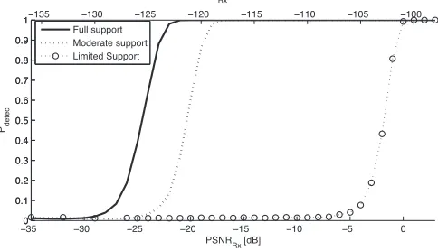
B. Spectrum Sensing
Spectrum sharing has been authorized in the 5 GHz radar bands (5150-5350 MHz and 5470-5725 MHz) opening up new spectrum for wireless access systems (WAS) and, in particular, wireless local area networks (WLAN) devices [42] [6]. To pro-tect radars from harmful interference, IEEE 802.11h WLAN devices employ a channel allocation mechanism, based on spectrum sensing, called Dynamic Frequency Selection (DFS). The stipulated DFS detection thresholds (-62 dBm and -64 dBm) are well above the noise floor (approximately -100 dBm) of WLAN receivers operating in this band. On the other hand, the radar’s low duty cycles and directional rotating antenna require that WLAN devices employ very long Channel Availability Check Times (60 s). This duration might even not be enough for very slowly rotating radars, as noted by the ITU-R, so an in-service monitoring scheme, consisting of interleaving data transmission with in-band sensing during devices’ normal operation, has also to be employed [6].
The DFS functionality, as initially developed, was incapable of ensuring the protection of terminal Doppler weather radar (TDWR) systems [43]. Interference investigations carried out by the FCC concluded that the considerations for the WAS systems’ adjacent-channel interference were not adequate and some modes of operation of TDWR systems were overlooked
in the dimensioning of the DFS certification requirements. Despite most of the DFS interference issues having been addressed in further recommendations, this episode serves as an example of the potential risks that spectrum sharing can bring to radar systems that concern safety-of-life applications, such as the ones operating at 5350-5470 MHz, if an inap-propriate interference and coexistence assessment is used. It also demonstrates the importance of making radio systems reconfigurable, as an efficient way to make them adaptive to dynamic policies, standards and protocols.
Although the DFS mechanism is now capable of protecting incumbents from low powerWLAN devices’ harmful interference, its one-size-fits-all detection threshold and availability check times, dimensioned for the worst case scenarios, lack the flexibility and intelligence of modern DSA techniques. In order to fully exploit the spatial and temporal aspects of radar bands, CR devices should be able to identify radar systems through their distinct transmitting features, namely scan period, transmit power, antenna gain, pulse duration, and PRF and, then, apply the appropriate sensing algorithms and detection thresholds and efficiently schedule the quiet intervals devoted to sensing.
Spectrum Sensing Specifications:
a) Detection threshold – As shown in [6], the required
detection thresholds for the protection of primary radar systems in the 5 GHz band are very high (from -61.7 dBm to -36.4 dBm). The main reasons behind these large values are these incumbent systems’ high transmit power and the absence of the hidden receiver problem. A similar conclusion can also be drawn for secondary radar systems. The protection of DME systems in the 960-1215 MHz band, for instance, would require sensing thresholds of -61 dBm for the interrogation and reply bands, as estimated in Appendix A. However, additional safety and aggregate interference margins can further reduce this value.
b) Sensing complexity – To detect and distinguish radar
signals from other communication systems’ interference or from different radar stations, CRs’ sensing algorithms should rely on peak detection techniques that are able to identify the sparse nature of radar signals, and estimate their respective parameters, such as PRF, pulse width, and scan period. However, identifying these parameters can be particularly complex in case of incumbent systems with very long antenna rotation periods, with random PRFs, or that employ frequency hopping techniques. The radar systems’ high transmit power (∼1 MW) and short pulse lengths (as low as 0.4 µs) also add to the complexity of the CR receiver, as they require analogue-to-digital converters (ADC) of high sampling rates and amplifiers of very large dynamic ranges.
c) Detection time/channel availability check time– The
d) Sensing periodicity – Radar channels’ occupation is usually constant over time and space, thus spectrum sensing only needs to be performed occasionally. There are, however, some exceptions such as military radioloca-tion systems that employ frequency hopping techniques, tracking systems, and systems placed on mobile plat-forms. Safety-of-life applications, such as ARNS, also require lower maximum interference times and, therefore, for their bands, SS must be performed more often.
e) In-band sensing – CR devices need to interleave their
transmissions with periods devoted to spectrum sensing in order to detect PU activity in the occupied radar channel [6]. Considering radar systems’ high transmit power, sensing can still be performed by the CR during nor-mal packet reception mode. Quiet periods might not be required for secondary radar systems if the interrogation and reply channels are located in separate frequencies (e.g. DME).
f) Ability to recognize spatial spectrum opportunities
– Not being affected by the hidden receiver problem, sensing can be an efficient way to exploit the spatial SOs of radar bands. However, the diversity of radiolocation systems coexisting in the same frequencies makes the one-size-fits-all detection threshold adopted for DFS in the 5 GHz band inadequate, as it leads to exclusion zones unnecessarily large for some PUs. In order to circumvent this issue, a CR has to somehow identify the thresholds and transmit power levels necessary to protect each of the radar systems within its interference range. Although distinguishing signals with origin in different radar sta-tions is technically possible through parameter estimation techniques, knowing the level of protection each of the detected stations requires is impossible without a priori information regarding their transmit power and maximum interference-to-noise ratio (INR).
The several techniques employed by a radar system to cancel interference, and its relatively low susceptibility to the effect of the aggregation of interference from multiple CRs, make the safety margins and aggregate interference margins added to the CRs’ detection thresholds small and, consequently, increase the number of recoverable WSs.
g) Ability to recognize temporal spectrum opportunities
– SS can ensure the protection of radar systems placed on mobile platforms or that operate on an intermittent basis, usually employed in radionavigation. In the case of secondary radar systems that operate on an ask-reply basis, CR devices might be able to opportunistically access these systems’ reply channels as long as they do not detect any signal in the respective interrogation channels. The complexity involved in the exploitation of temporal spectrum opportunities that stem from the radars’ predictable sweep patterns is high, due to the fact that radars may also receive interference from side-lobes and the challenges associated to the synchronization between CRs and radars’ sweep patterns, when the CR has no a priori information about the PU parameters. Some types of radar do not have predictable scan pat-terns, or may include receive-only periods used for noise calibration that should not be affected by CRs’ operation.
TABLE VI
SSSPECIFICATIONS FOR RADAR SYSTEMS
Requirements Cons Pros
Threshold safety-criticalDiversity; No hidden receiver; highEIRP; resilient
Complexity high dynamic rangeDiversity; low DC; High threshold
Time Low DC and high
rotation period High threshold
Periodicity High SM; mobile
systems
Predictability of most radar systems
In-band
sensing No UL/DL separation
Some exceptions (e.g. secondary radar)
Spatial
SOs High SM; diversity
No hidden receiver; radar robustness
Temporal
SOs Complexity; diversity
Predictability; protects mobile and intermittent
systems
The discussion regarding the adequacy of spectrum sensing in radar bands is summarized in table VI.
C. Cooperative Sensing
Cooperative sensing is not envisaged to be as attractive for radar bands as it is for TVWS, due to the absence of the hidden node problem in these bands. However, it can still bring some benefits, such as a reduction the local sensing time and periodicity of each CR node or providing an extra margin of protection to safety-critical systems, namely ARNS.
The discussion regarding CSS specifications in radar bands is provided next, and summarized in table VII.
a) Cooperative gain– The cooperative gain is low in radar
bands due to the absence of the hidden receiver problem. The fast fading caused by the constant radar beam motion creates temporal diversity between local sensing samples and reduces the gains obtained through cooperation.
b) Density of SUs– Considering radar stations’ long ranges,
the required density of SUs to perform cooperative sens-ing is not high.
c) Overhead – Radar bands’ radio environment is fairly
static, due to these systems’ fixed positions and param-eters and low density of deployment. There are, how-ever, some exceptions such as airborne radionavigation or frequency hopping systems. The time spent sensing could be significantly lower if CRs shared some of the information obtained through sensing. For instance, a CR through cooperation could get information from other SUs, regarding the antenna scan periods of the radars in its surroundings, and schedule its sensing intervals to match the instants when their main beams point at it.
d) Identification of spatial spectrum opportunities– As
TABLE VII
COOPERATIVE SENSING SPECIFICATIONS FOR RADAR BANDS
Requirements Cons Pros
Cooperative gain
No hidden receiver, fast
fading
-Density of SUs - Large-scale PUs
Overhead
High for mobile and frequency hopping
systems
Predictability; low number; reduction of
sensing time
Spatial SOs
Exposed node; SS limitations remain
unsolved
-Temporal SOs - Shorter sensing intervals
e) Identification of temporal spectrum opportunities –
By sharing sensing samples, the time spent by each CR performing sensing would be significantly reduced, which would allow a more efficient utilization of the spectrum.
D. Geolocation Database
Geolocation database represents an attractive spectrum ac-cess technique for the identification of spectrum opportunities in radar bands. In fact, it was proposed in the FCC’s NPRM 2012 as the primary technique to protect military and Fixed Satellite Services (FSS) communications in the 3550-3650 MHz band from small cells operating on an opportunistic basis [44]. The FCC, in this report, proposed the division of this band into three tiers of services: (i) Incumbent Access; (ii) Pri-ority Access; and (iii) General Authorized Access (GAA). The Incumbent Access tier would consist of authorized federal and legacy fixed satellite services, which would be guaranteed full protection from the remaining users. The Priority Access tier would be assigned to critical use facilities such as hospitals, utilities, government facilities and public safety entities with stringent QoS requirements. The GAA tier would accommo-date users operating on an opportunistic basis in zones where their operation would not interfere with incumbent and priority access systems. Both the Priority Access and GAA users would be required to register in a Spectrum Access System (SAS), crucial to define this hierarchical three-tier spectrum use structure. This system would delimitate the incumbent and priority access users’ exclusion zones based primarily on geolocation-enabled dynamic database techniques. The FCC is currently considering the implementation of these rules in the neighboring 3650-3700 MHz band, already used for commercial broadband services [45].
It is estimated that spectrum access techniques solely based on GL-DB will only allow approximately 40 % of the US population to benefit from the 3550-3650 MHz band [44]. The reason behind this low percentage is the fact that conservative exclusion zones of up to 450 km from the US shoreline will have to be defined to compensate for the Navy radar systems’ long transmit ranges and unknown/unplanned locations. As also stated in [44], [46], the adoption of more agile spectrum access techniques, namely spectrum sensing, in conjunction with GL-DBs could significantly reduce this
waste of spatial white spaces and, therefore, its deployment should be also considered.
Geolocation Database specifications:
a) Registration of legacy systems – Radar systems’
posi-tion and relevant operaposi-tional parameters can be available to the database. However, there might be strong opposi-tion from some military systems to provide informaopposi-tion to the database about their position or other classified information that make them more prone to be affected by enemy jammers.
b) Complexity/processing power – Most radar systems
have fixed position and operating parameters. Radar systems placed on airborne and shipborne platforms, however, may not have pre-planned routes and, there-fore, an error region has to be defined for such cases. Military radiolocation systems may also employ random frequency hopping techniques (ECCM), making their protection infeasible or inefficient using only the GL-DB technique. Radar systems usually have very long ranges, which reduces the required database grid resolution. From a security perspective, the database must be designed in a way that ensures that the classified information of, for example, military systems does not reach the general public.
c) Consultation periodicity/maximum dissemination
de-lay – For the less dynamic and unpredictable scenarios, CR devices would only need to access the database a few times per year to be fully updated regarding changes in radar systems’ parameters and positions. On the other hand, in the case of radar systems placed on mobile platforms, that operate on an intermittent basis or that employ frequency hopping techniques, the database would need to be consulted frequently in order for CR devices to check whether their emissions will cause harmful interference.
d) Ability to recognize spatial spectrum opportunities–
The position and parameters of radar systems are usually fixed, well known and can be made available to the database. Depending on its capabilities, the database can receive information in real-time regarding the aggregate interference SUs’ activity is inflicting on radar receivers and adapt the exclusion zones’ size accordingly [13]. The limited database grid resolution does not represent an issue in radar bands due to these systems’ very long ranges. However, conservative propagation models may need to be used in case of systems that concern safety-of-life (e.g. radionavigation). There might be also an interest, for security reasons, for military systems to not report accurate information about their position and operating parameters, which will reduce the efficiency of spatial sharing.
TABLE VIII
GL-DBSPECIFICATIONS FOR RADAR SYSTEMS
Requirements Cons Pros
Registration Classified information No uncertainty about PUs’ parameters
Complexity ECCM, mobile radar,
security
Planned, predictable; low grid resolution; low
number
Consultation periodicity
Mobile radars, ECCM: constantly
Fixed: few times per year
Spatial SOs
High penetration losses; safety-critical; classified information
Low uncertainty about PUs’ parameters
Temporal SOs
Mobile radars; time dynamics; classified
information
-predictable through theoretical propagation models if no considerations are made regarding the terrain elevation or other possible obstructions.
e) Ability to recognize temporal spectrum opportunities
– Exploiting the radar antennas’ predictable sweep pat-terns is infeasible using only GL-DB, due to the relatively fast rotation. To account for the mobility of radar systems placed aboard aircraft or ships, an error region must be defined. For example, in the case of a radar antenna aboard an airplane flying at 900 km/h and with a database consultation periodicity of 5 min., the error region radius would be
Rerr = 900605 = 75km. (1)
Adding 75 km to the aircraft exclusion zones’ radius would greatly reduce the amount of recoverable white spaces in ARNS bands in every country.
The previous discussion is summarized in table VIII, where it is evident the inability of a GL-DB to protect mobile PUs and its inefficiency at exploiting temporal spectrum opportu-nities.
E. Geolocation Database + Spectrum Sensing
An SU with SS capability can more efficiently exploit the spatial and temporal aspects of secondary access in radar bands than with a GL-DB, because it relies on real-time RF measurements of the signal path loss to infer the interference it causes to PUs, without being affected by the hidden receiver problem like in TVWS. However, it is technically challenging and complex for CR devices to extract information about radars’ EIRP, sweep periodicity, main-beam to side-lobe ratio and modulation, based solely on SS results. A database-aided SS scheme, where information about the incumbents’ technical parameters is provided to SUs by a centralized database, combines the best aspects of both techniques. Knowing in advance what types of radars are operating nearby, CR devices could adapt their detection thresholds, sensing intervals and algorithms and schedule transmissions when the radar main beam is not pointed at them. Some of this information, however, may not be open to the public when it concerns military radiolocation systems. The effect of the aggregation of interference could also be mitigated if radars reported to the
database, in real-time, the level of interference they are being subject to and the database, based on these values, adapted the detection thresholds CRs should use [13].
A hybrid GL-DB+SS scheme could also be appealing in “low risk” regions, that is, areas sufficiently far away from any radar, where the chance of CR operation inflicting any harmful interference is pratically zero. A CR device located in one of these regions could be authorized by the database to not employ spectrum sensing, which would translate into higher throughput and reduced battery consumption, which is especially important for handheld devices.
F. Beacon Signaling
The deployment of the beacon signalling approach in radar bands has not yet received much attention in the literature, mainly due to the focus on GL-DB and DFS for these bands by regulatory entities [44] [42] [6]. Nonetheless, beacon signalling can still be employed in support of SS in the identifi-cation of radar systems’ transmitting parameters and temporal spectrum opportunities, avoiding significant increases in CR devices’ complexity.
Through some alterations in their structure, radar signals could carry information regarding their transmit power, gain, rotation period, modulation, pulse rate frequency, beam width, etc. Alternatively, radar systems could also send Channel Allocation Frames (CAF) between pulses that would be de-tected and used by opportunistic secondary systems to avoid transmission when the radar main beam is pointing towards them [47], [48]. If these data were transmitted at a power somewhat similar to the traditional radar pulse, they could be easily decoded outside these systems’ exclusion zone (e.g. at a received power below -64 dBm for the 5 GHz band).
The description of how a beacon device would be designed and its costs and performance is described next and in table IX.
Beacon signaling specifications:
a) Design limitations – The beacons could be co-located
with radar systems and transmit at a similarly high power. In order not to affect incumbents’ operation, they could employ interference mitigation techniques based on:
• frequency separation using a dedicated channel;
• an additional antenna with non-intersecting pattern [39], which would ask CRs to interrupt their commu-nications before being swept by the radar main beam;
• transmission between radar pulses inside the inter-measuring gap (IMG) [47], [48]; or
• transmission of low duty cycle asynchronous signals easily suppressed by radar systems through Interference Rejection (IR) techniques.