Preliminary and Confidential
Copyright
Copyright © 1990–1997 Auspex Systems, Inc. All rights reserved. Printed in the United States of America. Part Number 850471-001 Revision A, November 1997.
No part of this publication may be reproduced, in any form or by any means, without the prior written consent of Auspex Systems, Inc.
Auspex Systems, Inc., reserves the right to revise this publication and make changes in content without obligation on the part of Auspex Systems to provide prior notification of such revision or change.
RESTRICTED RIGHTS LEGEND: Use, duplication, or disclosure by the Government is subject to restrictions as set forth in subparagraph (c)(1)(ii) of the Rights in Technical Data and Computer Software Clause at DFARS 252.227-7013 (October 1988) and FAR
52.227-19(c) (June 1987) and in similar clauses in the FAR and NASA FAR supplement.
Trademarks
Auspex, the Auspex logo design, Functional Multiprocessor, Functional Multi-processor, Functional Multi-processing, Functional Multiprocessing, Functional Multiprocessing Kernel, FMK, FMP, and NS 5000 are registered trademarks of Auspex Systems, Inc. NS 7000, NS 6000, NS 6002, NS 5500, NS 5502, NS 3000, NetServer, DataGuard,
DriveGuard, ServerGuard, and Thrive Carefully are trademarks of Auspex Systems, Inc. SPARC is a registered trademark of SPARC International. Sun, SunOS, Network File System, NFS, and Sun Microsystems are trademarks or registered trademarks of Sun Microsystems, Inc. UNIX is a registered trademark of X/Open Company Limited. VMEbus is a trademark of VMEbus Manufacturers Group. VT510 and DEC are trademarks of Digital Equipment Corp. ForeRunner is a trademark of FORE Systems, Inc.
XWindows is a trademark of MIT.
FCC Statement
WARNING: This equipment has been tested and found compliant with the limits for a Class A digital device, pursuant to Part 15 of the FCC rules. These limits are designed to provide reasonable protection against harmful interference when the equipment is operated in a commercial environment. This equipment generates, uses, and can radiate radio frequency and, if not installed and used in accordance with the instruction manual, may cause harmful interference in which case the user will be required to correct the interference at his own expense.
Preliminary and Confidential
▲ iii
Declaration of Conformity
The Auspex NetServers meet the following safety and EMC standards pursuant to ISO/IEC Guide 22 and EN 45014:
The NetServer complies with the requirements of the Low Voltage Directive 73/23/EEC
and the EMC Directive 89/336/EEC. This equipment has been tested and found compliant pursuant to CISPR22/85 Class A.
Notice of VCCI Compliance
This is a Class A product based on the standard of the Voluntary Control Council for Interference by Information Technology Equipment (VCCI). If this equipment is used in a domestic environment, radio disturbance may arise. When such trouble occurs, the user may be required to take corrective actions.
Protection Against Electrostatic Discharge
To prevent damage to the system due to electrostatic discharge, always wear the antistatic wrist strap provided with your network server when you come in contact with the system.
Publication Change Record
The following table records all revisions to this publication. The first entry is always the publication’s initial release. Each entry indicates the date of the release and the number of the system release to which the revision corresponds.
NetServer Model Standards
NS 7000/800 Series NetServer: NS 7000/800 (base cabinet) NS 7000/080 (expansion cabinet) NS 7000/810 (base cabinet and expansion cabinet)
EN60950/1992 EN60950 A1/1993 EN60950 At2/1993 DIN VDE 0805 A1/11.91 EN55022 Class A (1985 Ed 1) EN50082-1 (Draft 1992)
IEC801-2 (1991): ESD, 8 kv air, 4 kv contact IEC801-3 (1984): RS, 10 v/m, 1 kHz modulated IEC801-4 (1988): EFT, 2 kv A/C cables, 1 kv I/O cables IEC801-5 (Draft 1993): Surge, 2 kv diff, 4 kv comm
Part Number Date Description
Contents ▲ v
Noble:Desktop Folder:files:1.9.2_NS7000_800:HWIG TOC;Novem-ber 25, 1997 4:20 pm
Contents
Chapter 1 Overview of the NS 7000/800
Overview . . . 1-1 Processor Board Configurations. . . 1-5 Disk Subsystems. . . 1-6 Seven-Slot Drive Rack. . . 1-6 High-Density Disk Array (HDDA) . . . 1-6 Power Subsystems . . . 1-7 Numbering Conventions. . . 1-8 Environmental Requirements. . . 1-9 Space Requirements . . . 1-9 Electrical Requirements. . . 1-10 Power Cables. . . 1-11 North America, Canada, and Mexico . . . 1-11 International . . . 1-11
Chapter 2 Unpacking and Setting Up the System
About This Chapter . . . 2-1 Unpacking the NetServer . . . 2-2 Stabilizing the Cabinet. . . 2-5 Opening the Cabinet Doors . . . 2-5 NetServer Components . . . 2-6 Base Cabinet Subassemblies . . . 2-7 Expansion Cabinet Subassemblies. . . 2-10 Card Cage Components . . . 2-13 HP VIII . . . 2-13 NP IV . . . 2-15 SP V . . . 2-17 Processor Board Slot Assignments. . . 2-18 Power Supply Configurations . . . 2-19 Main Power Supplies . . . 2-19 Bulk Power Supplies . . . 2-19 Disk DC Converter (DCC) . . . 2-19
Chapter 3 Installation
About This Chapter . . . 3-1 Grounding the NetServer . . . 3-2 Installing the Antistatic Wrist Strap. . . 3-4 Connecting the System Console. . . 3-5 Network Cable Connections. . . 3-7 Network Interface Numbering. . . 3-12
ber 25, 1997 4:20 pm
Chapter 4 Power On and Shut Down
About This Chapter . . . .4-1 Powering On the NetServer . . . .4-2 Power-On Self Test and Boot Sequence. . . .4-3 Shutting Down the NetServer. . . .4-9
Chapter 5 Preventive Maintenance
About This Chapter . . . .5-1 Power Subsystem Operation. . . .5-2 Base Cabinet PDU . . . .5-2 Expansion Cabinet PDU . . . .5-2 Main Power Supply. . . .5-3 Bulk Power Supplies . . . .5-4 Disk DC Converter (DCC) . . . .5-5 HDDA Drive Drawer LEDs . . . .5-7 Drive LEDs . . . .5-7 Disk DCC LED . . . .5-8 Preventive Maintenance LED . . . .5-9 Cleaning the NetServer Air Filter. . . .5-10 Fan Trays and Fan Tray LEDs . . . .5-12 Processor Board LEDs . . . .5-13 Host Processor . . . .5-13 Network Processor . . . .5-13 ATM LEDs . . . .5-13 FDDI-SAS LEDs . . . .5-15 FDDI-DAS LEDs . . . .5-16 Quad Ethernet LEDs . . . .5-18
Appendix A Drive Configuration Options
About This Appendix. . . A-1 Drive Configuration Guidelines. . . A-2 Drive Naming Conventions . . . A-3 Disk Drives . . . A-3 HDDA Drives . . . A-3 Tape Drives . . . A-3 CD-ROM Drives. . . A-4 Sample Drive Configurations . . . A-5 Adding, Removing, and Replacing Drives . . . A-8 Adding, Removing, and Replacing Drives in the Drive Rack . . . A-8 Adding, Removing, and Replacing HDDA Drives. . . A-14
Appendix B Cable Specifications
ber 25, 1997 4:20 pm
Contents ▲ vii
NS 7000 Model 800 Series Hardware Manual ▲ ix
Noble:Desktop Folder:files:1.9.2_NS7000_800:HWIG LOF;Novem-ber 25, 1997 5:53 pm
Figures
Figure 1-1. NS 7000/800 Series NetServer . . . 1-2 Figure 1-2. NS 7000/800 FMP architecture. . . 1-4 Figure 1-3. Outline of the L6-20 and L6-30 power plugs . . . 1-11
Figure 2-1. Stabilizing the cabinet . . . 2-5 Figure 2-2. Base cabinet subassemblies (front view). . . 2-8 Figure 2-3. Base cabinet subassemblies (back view) . . . 2-9 Figure 2-4. Expansion cabinet (front view). . . 2-11 Figure 2-5. Expansion cabinet (back view) . . . 2-12 Figure 2-6. HP front panel. . . 2-14 Figure 2-7. Example of mixed network interfaces on NP boards . . . 2-16 Figure 2-8. System processors . . . 2-17
Figure 3-1. Main power switch (back view of base cabinet) . . . 3-2 Figure 3-2. Main power switch (back view of expansion cabinet) . . . 3-3 Figure 3-3. Antistatic wrist strap (back view of base cabinet) . . . 3-4 Figure 3-4. Routing cables to the NetServer . . . 3-6 Figure 3-5. Connection to Quad 10/100Base-T Ethernet ports . . . 3-7 Figure 3-6. Connection to Quad 10Base-T Ethernet ports . . . 3-8 Figure 3-7. Connection to half-duplex 100Base-T Ethernet ports . . . 3-8 Figure 3-8. Connection to full-duplex 100Base-T Ethernet ports . . . 3-9 Figure 3-9. Connection to FDDI (fiber) ports . . . 3-9 Figure 3-10. Connection to FDDI (MLT-3) ports . . . 3-10 Figure 3-11. Connection to ATM (fiber) ports . . . 3-10 Figure 3-12. Connection to ATM (UTP) ports . . . 3-11 Figure 3-13. Example network interface numbering on the NP boards. . . 3-14 Figure 3-14. Installing a drive in the seven-slot drive rack . . . 3-15 Figure 3-15. Drive drawer front panel. . . 3-18 Figure 3-16. Installing a drive drawer . . . 3-19 Figure 3-17. Cam lever engaging in cam slot . . . 3-19 Figure 3-18. Latching the drive drawer. . . 3-20 Figure 3-19. Location of retaining screw (drawer front panel) . . . 3-20 Figure 3-20. Locking the drive drawer . . . 3-21
ber 25, 1997 5:53 pm
Figure 5-7. EMI screen location . . . .5-10 Figure 5-8. Air filter location (front view of base cabinet) . . . 5-11 Figure 5-9. Fan trays (front view of base cabinet) . . . .5-12 Figure 5-10. Fan tray LEDs (back view of base cabinet) . . . .5-12 Figure 5-11. ATM (fiber) LEDs . . . .5-14 Figure 5-12. ATM (UTP) LEDs . . . .5-14 Figure 5-13. FDDI-SAS (fiber) LED display . . . .5-15 Figure 5-14. FDDI-SAS (MLT-3) LED display . . . .5-16 Figure 5-15. FDDI-DAS LED display. . . .5-17 Figure 5-16. Quad Ethernet LEDs . . . .5-18
Figure A-1. Sample drive rack configuration (front view) . . . A-5 Figure A-2. Sample drive drawer configuration (top view) . . . A-5 Figure A-3. Base cabinet drive names. . . A-6 Figure A-4. Expansion cabinet drive names . . . A-7 Figure A-5. Inserting a drive in the seven-slot drive rack . . . A-9 Figure A-6. Inserting a drive in the seven-slot drive rack . . . A-13 Figure A-7. Unlocking the HDDA drive drawer. . . A-15 Figure A-8. Opening the drive drawer . . . A-15 Figure A-9. Inserting a drive in a drive drawer . . . A-16 Figure A-10. Latching the HDDA drive into position . . . A-16 Figure A-11. Closing the HDDA drive drawer . . . A-17 Figure A-12. Cam lever engaging in cam slot . . . A-18 Figure A-13. Latching the HDDA drive drawer . . . A-18 Figure A-14. Locking the HDDA drive drawer. . . A-19 Figure A-15. Unlocking the HDDA drive drawer. . . A-21 Figure A-16. Opening the drive drawer . . . A-21 Figure A-17. Unlatching the HDDA drive . . . A-22 Figure A-18. Removing an HDDA disk drive . . . A-22 Figure A-19. Closing the HDDA drive drawer . . . A-23 Figure A-20. Cam lever engaging in cam slot . . . A-23 Figure A-21. Latching the HDDA drive drawer . . . A-24 Figure A-22. Locking the HDDA drive drawer. . . A-24 Figure A-23. Unlocking the HDDA drive drawer. . . A-27 Figure A-24. Opening the drive drawer . . . A-27 Figure A-25. Unlatching the HDDA drive . . . A-28 Figure A-26. Removing an HDDA disk drive . . . A-28 Figure A-27. Inserting a drive in a drive drawer . . . A-29 Figure A-28. Closing the HDDA drive drawer . . . A-30 Figure A-29. Cam lever engaging in cam slot . . . A-30 Figure A-30. Latching the HDDA drive drawer . . . A-31 Figure A-31. Locking the HDDA drive drawer. . . A-32
NS 7000 Model 800 Series Hardware Manual ▲ xi
Noble:Desktop Folder:files:1.9.2_NS7000_800:HWIG LOT;Novem-ber 25, 1997 5:01 pm
Tables
Table 1-1. NS 7000/800 NetServer hardware features . . . 1-3 Table 1-2. NS 7000/800 processor board configurations . . . 1-5 Table 1-3. NS 7000/800 numbering conventions . . . 1-8 Table 1-4. NS 7000/800 environmental requirements . . . 1-9 Table 1-5. NS 7000/800 space requirements . . . 1-9 Table 1-6. NS 7000/800 power requirements . . . 1-10 Table 1-7. NS 7000/800 power specifications. . . 1-10
Table 2-1. HP memory configurations. . . 2-13 Table 2-2. Network interface configurations . . . 2-15 Table 2-3. NP IV memory configurations . . . 2-17 Table 2-4. Processor board slot allocations . . . 2-18
Table 3-1. Setup parameters for system consoles . . . 3-5 Table 3-2. ATM network interface numbering. . . 3-12 Table 3-3. Quad 10/100Base-T Ethernet addressing . . . 3-13
Table 5-1. Main power supply LED status . . . 5-3 Table 5-2. Bulk power supply LED status. . . 5-5 Table 5-3. Disk DCC LED status. . . 5-6 Table 5-4. Drive LED status. . . 5-7 Table 5-5. Disk DCC LED status. . . 5-8 Table 5-6. Preventive maintenance LED status . . . 5-9 Table 5-7. RingOP LED indicators on the FDDI-DAS SBus card . . . 5-16
Table A-1. CD-ROM drive naming conventions. . . A-4
Table B-1. Pin diagram for SCSI-2 connectors . . . .B-3
Preface ▲ xiii
Preliminary and Confidential
Preface
About This Manual
This manual describes the Auspex NS 7000™ Model 800 Series NetServer™ and provides procedures for installing hardware components. It is intended for users who are familiar with computer equipment installation procedures and network cabling.
Before setting up the server or installing server components, Auspex recommends that you read this entire manual to familiarize yourself with the system.
The manual includes the following chapters and appendices:
▲ Chapter 1, “Overview of the NS 7000/800”
▲ Chapter 2, “Unpacking and Setting Up the System” ▲ Chapter 3, “Installation”
▲ Chapter 4, “Power On and Shut Down” ▲ Chapter 5, “Preventive Maintenance” ▲ Appendix A, “Drive Configuration Options” ▲ Appendix B, “Cable Specifications”
▲ Appendix C, “Configuring the System Console”
Related Documentation
The following Auspex documents contain additional information relevant to managing and maintaining Auspex NetServers:
Preliminary and Confidential
Typographical Conventions
This guide uses typefaces to indicate different types of information. The following table explains the different typefaces.
Special Messages
This manual uses the following special messages and icons:
Warning: Warnings alert you to the danger of personal injury and call attention to instructions you must follow for your personal safety.
Caution: Cautions call attention to instructions you must follow to prevent damage to system hardware or software, or loss of system data.
Note: Notes call attention to important information you should be aware of as you follow the procedures outlined in this guide.
Recommendation: Recommendations call attention to an item or procedure that is not required but might help improve performance, ease of use, and ease of installation or configuration.
Tools
The tools icon identifies the tools you need to complete a task.
Font Meaning
Typewriter Indicates literal screen messages.
Bold In a command line, indicates information to be entered exactly as shown. In text, indicates a command name or device name.
Preliminary and Confidential
Preface ▲ xv
Terminology
Throughout this manual, certain terms refer to NetServer families generically. Where distinctions are necessary, the actual machine model is used.
Host Processor PROM monitor prompts are represented as “HP>” throughout this manual. Since this system prompt varies depending on the Host Processor model installed in the NetServer, the prompt that appears on your system might be different.
Contacting Auspex
Customer service and help using electronic mail are available to North American and International customers.
North America
You can reach Auspex customer service for North America 24 hours a day by dialing 1-800-3-AUSPEX (1-800-328-7739).
You can also obtain customer service support by sending electronic mail to [email protected].
The generic term... Describes these models...
NS 7000/800 NS 7000 Model 800 Series NetServer
NS 7000/810 NS 7000 Model 800 Series NetServer with expansion cabinet
Preliminary and Confidential
International
Customers within the countries or territory listed as follows can reach Auspex customer service 24 hours a day by dialing the provided telephone number:
Customers within the locations listed can also obtain help through electronic mail at the addresses listed under the “North America” section.
All other international customers should contact their authorized Auspex distributor.
Technical Publications
To comment on the content of this publication, send email to Auspex Technical Publications at the following address:
World Wide Web
To access information about Auspex Systems, Inc. and its products, use the following resource location on the World Wide Web:
http://www.auspex.com
Country or territory Telephone number Country or territory Telephone number
Australia 1-800-121-194 Luxembourg 0800-2721 Austria 0-660-7912 Malaysia 800-4509 Belgium 0800-1-0180 Netherlands 06-0222158 Denmark 80-01-03-60 Norway 800-1-1294 France 0800-91-21-32
(0800-26-38-22)*
* France has two toll-free numbers. The number in () is directed to the Paris office during the working day.
Philippines 1-800-116-0005
Overview of the NS 7000/800 ▲ 1-1
Preliminary and Confidential
1
Overview of the NS 7000/800
Overview
Auspex NetServers deliver industry-leading system response time, throughput, and reliability to meet the needs of large network environments. The patented Functional Microprocessing® (FMP®) architecture distributes file system workloads to multiple, dedicated system processors individually optimized for network, file, storage, and UNIX system functions. The FMP architecture also provides enhanced user productivity over traditional servers by delivering higher data availability, increased data accessibility, and reduced administrative costs through data consolidation.
Enhanced disk, power, and storage subsystems make Auspex NetServers capable of operating efficiently under a variety of conditions and environments.
Overview ▲ 1-3
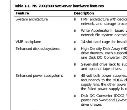
[image:19.792.142.549.107.461.2]Table 1-1 lists the hardware features available with the NS 7000/800.
Table 1-1. NS 7000/800 NetServer hardware features
Feature Description
System architecture ▲ FMP architecture with dedicated system processors for file, network, and storage processing.
▲ Write Accelerator III board with the SP V for improved network file system operations.
VME backplane ▲ 14-slot card cage for installing the processor boards. Enhanced disk subsystems ▲ High-Density Disk Array (HDDA) chassis consisting of four
drive drawers, each supporting up to seven disk drives and one Disk DC Converter (DCC).
▲ Seven-slot drive rack to support the root drive, CD-ROM, and optional tape drives.
Enhanced power subsystems ▲ 48-volt bulk power supplies, providing optional N+1 redundancy to the HDDA chassis; meaning if one power supply fails, the other power supplies maintain power while the failed power supply is replaced.
▲ Disk DC Converter (DCC) for converting the 48-volt bulk power into 5-volt and 12-volt power for the disk drives in the drive drawer.
Storage subsystems ▲ Tape storage systems that can be attached to the HP or SP boards. For information on supported tape storage systems, refer to the Storage Peripherals Manager’s Guide. Networking*
* Contact your Auspex sales representative for the latest information on supported network interfaces.
▲ Support for 100Base-T Ethernet, Quad 10Base-T Ethernet, Quad 10/100Base-T Ethernet, FDDI, and ATM network interfaces.
Preliminary and Confidential
Figure 1-2 illustrates the NetServer’s Functional Multiprocessing architecture. For more information on NetServer operation, refer to the System Manager’s Guide.
Figure 1-2. NS 7000/800 FMP architecture Network connections:
Ethernet, FDDI, ATM
6 independent SCSI channels
FMP I/O backplane
UNIX memory 32–384 MB
CPU MVIC
UNIX
SBus
I/O cache memory 64–256 MB CPU CPU Protocols Files Network Processor SBus
Preliminary and Confidential
[image:21.792.137.554.132.376.2]Processor Board Configurations ▲ 1-5
Processor Board Configurations
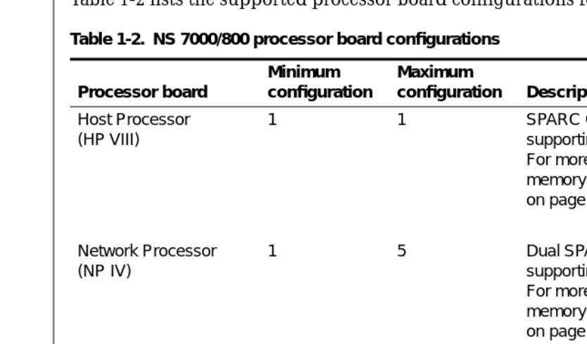
[image:21.792.137.553.141.719.2]Table 1-2 lists the supported processor board configurations for the NS 7000/800.
Table 1-2. NS 7000/800 processor board configurations
Processor board
Minimum configuration
Maximum
configuration Description
Host Processor (HP VIII)
1 1 SPARC CPU Host Processor supporting up to 384 MB of memory. For more information on HP VIII memory configurations, see Table 2-1 on page 2-13.
Network Processor (NP IV)
1 5 Dual SPARC CPU Network Processor supporting up to 256 MB of memory. For more information on NP IV memory configurations, see Table 2-3 on page 2-17. For a list of supported network interfaces, refer to Table 2-2 on page 2-15.
Storage Processor (SP V)
Preliminary and Confidential
Disk Subsystems
The NS 7000/800 base cabinet houses two types of disk subsystems:
▲ Seven-Slot Drive Rack
▲ High-Density Drive Array (HDDA)
Each of these disk subsystems is described as follows.
Seven-Slot Drive Rack
The seven-slot drive rack supports any combination of disk, tape, and CD-ROM drives, with one drive configured as the root drive. Each NS 7000/800 base cabinet supports only one seven-slot drive rack.
Note: NS 7000/080 expansion cabinets do not support seven-slot drive racks.
High-Density Disk Array (HDDA)
Each NS 7000/800 base cabinet supports up to two HDDA chassis. Each HDDA chassis supports up to four individual drive drawers. Each drive drawer supports up to 7 disk drives for a maximum of 28 disk drives per HDDA chassis. The drive drawer configuration increases drive density in the NetServer and reduces the physical space needed for a high-capacity server.
Note: The drive drawers support disk drives only. They do not support CD-ROM or tape drives.
For additional disk storage you can add an expansion cabinet, which supports up to five HDDA chassis. The maximum number of drives supported in a fully configured
Preliminary and Confidential
Power Subsystems ▲ 1-7
Power Subsystems
The NS 7000/800 has three types of power subsystems:
▲ Main ▲ 48-volt bulk ▲ Disk DCC
The NetServer power subsystems provide flexibility to build and scale system storage solutions to meet individual requirements.
The design of the NetServer power subsystems also offers optional “N+1” redundancy for two of the three power subsystems: the base cabinet main power and the 48-volt bulk power for the HDDAs. N+1 redundancy means that for a specific configuration, a single power supply can fail without interrupting system operation. Power supply redundancy also offers the ability to hot plug power supplies in the event of a failure.
The main power supplies in the base cabinet convert AC voltage to DC voltage for the card cage processor boards and seven-slot drive rack. The base cabinet comes standard with two main power supplies. For redundancy, you need to add an additional main power supply. The maximum number of main power supplies in the base cabinet is three. The bulk power supplies convert the 240-volt power into 48-volt power for distribution to the drive drawer Disk DCCs. Each NS 7000/800 NetServer shipped from Auspex is configured with the same number of bulk power supplies as there are HDDA chassis. For example, the base cabinet comes standard with one HDDA chassis, one drive drawer, and one bulk power supplies—one supply for each HDDA chassis. For redundancy, you need to add an additional power supply. The maximum number of bulk power supplies in the base cabinet is three. The maximum number of bulk power supplies in an expansion cabinet is six.
The custom design and packaging of the Disk DCC power subsystems provides the flexibility to build and scale drive storage requirements to site requirements because Disk DCC power is added as you add drive drawers. Each Disk DCC converts the 48-volt bulk power into 5-volt and 12-volt power for the HDDA disk drives.
For more information on power subsystem configuration, refer to “Power Supply
Numbering Conventions
Table 1-3 describes the numbering conventions for each element in the NetServer.
For information regarding specific locations and setup of NetServer components and subassemblies, refer to Chapter 2.
Table 1-3. NS 7000/800 numbering conventions
NetServer element How numbered Numbering convention
Card cage/ VME backplane
1–14 The HP board is always installed in slots 1 and 2. The NP and SP boards are installed thereafter and occupy one double slot or two single slots each. A maximum of 5 NP boards and 5 SP boards are supported per system. Seven-slot drive rack ad0–ad6 Drives in the seven-slot drive rack are
numbered from left to right. The first drive (ad0) is always installed in slot 0, and is configured as the root drive.
HDDA chassis 1–2 (base cabinet) 1–5 (expansion cabinet)
HDDA chassis are numbered from bottom to top in both the base cabinet and expansion cabinet.
HDDA drive drawers 1–4 Each HDDA chassis supports up to four drive drawers. Each drive drawer supports up to 7 disk drives and 1 Disk DCC per drawer.
HDDA disk drives ad7–ad63 (base cabinet) ad64–ad203 (expansion cabinet)
HDDA drives are numbered
Environmental Requirements ▲ 1-9
Environmental Requirements
Operate the NetServerin a temperature-controlled, contaminant-free atmosphere within the recommended levels of humidity.
Table 1-4 lists the environmental requirements for the NS 7000/800.
Caution: For proper air flow and EMI reduction, operate the NetServer with the doors closed and all access panels in place.
Note: The NetServer can operate at an altitude of up to 3,000 m (10,000 ft.). However, the maximum operating temperature at an altitude between 2,150 m (7,000 ft.) and 3,000 m (10,000 ft.) is 30°C (86°F).
Space Requirements
Place the NetServer base cabinet in a location no less than 3-feet from the nearest wall or other equipment. Three feet of clearance allows easy access to the server and permits adequate air flow around the equipment.
If your NetServer includes an expansion cabinet, you must allow enough space for the base cabinet and expansion cabinet to stand side by side.
Table 1-5 lists the dimensions of the NetServer base cabinet and optional expansion cabinet. The weights shown are for fully configured cabinets.
Table 1-4. NS 7000/800 environmental requirements
Environmental requirements Minimum Maximum
Operating temperature 5°C (40°F) 35°C (95°F) Storage temperature 0°C (32°F) 65°C (150°F) Operating altitude 0 m (0 ft.) 2,150 m (7,000 ft.) Storage altitude 0 m (0 ft.) 12,000 m (40,000 ft.) Operating humidity
(noncondensing at 40°C)
20% 80%
Nonoperating humidity (noncondensing at 40°C)
10% 90%
Acoustics (sound power) N/A Less than 7.5 dBA bels (LwA)
Table 1-5. NS 7000/800 space requirements
Dimension Base cabinet Expansion cabinet
Electrical Requirements
The NetServer requires an electrical power source that is free of electrical power surges and must be adequately grounded to protect it from EMI during operation.
Caution: If you have an expansion cabinet connected to the base cabinet, the expansion cabinet must be powered from a different electrical circuit than the base cabinet.
Maintaining proper environmental humidity also helps reduce the risk of electrostatic damage.
Warning: The wiring at your site must provide for ground fault protection. Avoid installation during lightning storms.
Tables 1-6 and 1-7 list the electrical power requirements and electrical specifications for the base cabinet and expansion cabinet.
Caution: The base cabinet and expansion cabinet accept a nominal input voltage range of 200–240 VAC only.
Table 1-6. NS 7000/800 power requirements Base cabinet Expansion cabinet
2,600 VA 3,650 and 4,400 VA 9,050BTUs/Hour 12,450 BTUs/Hour
Table 1-7. NS 7000/800 power specifications
Specification Base cabinet Expansion cabinet
Nominal input voltage range 200–240 VAC 200–240 VAC Operating input voltage range 180–264 VAC 180–264 VAC
Current rating 16 A 24 A
Input service rating 20 A 30 A Frequency 50–60 ±3 Hz 50–60 ±3 Hz Inrush current 20 A peak maximum per
power supply
30 A peak maximum per power supply
Power factor 0.98 0.98
Power Cables ▲ 1-11
Power Cables
This section describes the power cables shipped with the NS 7000/800.
North America, Canada, and Mexico
For North America, Canada, and Mexico the base cabinet and expansion cabinet are shipped with 3-12 gauge L6-20 and L6-30 power cables. The wall outlet must be on a 20-amp for the base cabinet or a 30-amp circuit for the expansion.
Figure 1-3 shows an outline of the L6-20 and L6-30 power plugs.
Figure 1-3. Outline of the L6-20 and L6-30 power plugs
International
For International configurations, the NetServer is shipped with a TUV-approved 3x1.50-mm cable, which meets the specifications outlined in the HD21 code H05VVF3G1.50.
Unpacking and Setting Up the System ▲ 2-1
2
Unpacking and Setting Up
the System
About This Chapter
This chapter provides instructions for unpacking and setting up the NetServer base and expansion cabinet and includes information to help you familiarize yourself with the NetServer’s components.
The following sections are covered in this chapter:
▲ Unpacking the NetServer ▲ Stabilizing the Cabinet ▲ Opening the Cabinet Doors ▲ NetServer Components ▲ Base Cabinet Subassemblies ▲ Expansion Cabinet Subassemblies ▲ Card Cage Components
▲ Processor Board Slot Assignments ▲ Power Supply Configurations
Unpacking the NetServer
This section provides unpacking procedures for the NetServer base cabinet, expansion cabinet, and HDDA drive drawers. This procedure varies depending on the shipping method and packing materials used.
NetServers delivered to destinations within the continental United States are usually shipped by truck. NetServers delivered to destinations outside the continental United States are shipped by air.
Warning: Do not attempt to move or uncrate the base cabinet unless you have others to assist you. You need at least one person to help you uncrate the expansion cabinet. Any attempt by one person to uncrate the base or expansion cabinet could result in injury.
Tools
▲ Knife or other sharp object ▲ Wire cutter
▲ Crescent wrench ▲ #1 Phillips screwdriver
If the server is in a crate, you need the following:
▲ 9/16-inch wrench ▲ Band or wire cutter
To unpack a NetServer shipped by truck
1. Place the NetServer base cabinet in its designated location.
For easy access and proper air circulation, make sure there is at least three feet of clearance between the server and any wall or other equipment (except the expansion cabinet). Also, make sure there is a wall receptacle within six feet of the server and a telephone jack (for modem users) within seven feet of the base cabinet. The wall receptacle must be on a 20-amp circuit.
2. Remove packing material from the base cabinet by sliding it up and off the unit. To avoid damaging the unit, do not cut the packing material with a knife.
3. If your NetServer includes an optional expansion cabinet:
a. Place the expansion cabinet to the left of the base cabinet (when viewed from the front).
Unpacking the NetServer ▲ 2-3 Note: If the surface of the server becomes marked or smudged, use a
nonabrasive stainless-steel cleaner to clean the surface. Be sure to allocate enough space for this procedure.
To unpack a NetServer shipped by air
1. Use a 9/16-inch wrench to remove the seven bolts securing the side panels of the crate to its base.
2. Turn the six latch locks counterclockwise to release the locks securing the packing crate’s front panel. After releasing the locks, carefully lower the panel to the ground. Keep the panel nearby. It will be used in step 5 as a ramp to roll the server off the base of the crate.
3. Slide the panels off the server, and move them aside.
4. Cut and remove the straps that secure the server to the base of the crate.
5. Place the ramp (the panel removed in step 2) next to the edge of the crate, adjacent to the back panel of the server. At the lower end of the ramp, fold out the ramp extension to make a smooth transition from ramp to floor.
6. Carefully roll the server down the ramp to the floor.
Caution: Make sure that the high end of the ramp is slightly lower than the base of the crate, or theserver’s casters may move the ramp out of position as you roll it onto the ramp. Also, check that the leveling feet clear the upper edge of the ramp extension. If the feet catch on the extension, the cabinet can fall off the ramp.
7. Remove the plastic packing material from the server by sliding it up and off the unit. 8. To avoid damaging the unit, do not cut the plastic packing material with a knife. 9. Before proceeding further, roll the server to the site prepared for it.
For easy access and proper air circulation, make sure there is at least three feet of clearance between the server and any wall or other equipment (except the expansion cabinet). Also, make sure that there is a wall receptacle within six feet of the server and a phone jack (for modem users) within seven feet of the base cabinet. The wall receptacle must be on a 16-amp circuit.
10. If your NetServer includes an optional expansion cabinet, repeat steps 1 through 9 to unpack it. Place the expansion cabinet to the left of the base cabinet (when viewed from the front).
Note: If the surface of the server becomes marked or smudged, use a nonabrasive stainless-steel cleaner to clean the surface.
To unpack an HDDA drive drawer
1. Using a knife or other sharp tool, remove the drive drawer from its shipping container.
2. Remove the black rubberbands securing the packing material, and put in a safe place.
Caution: Do not cut the black rubberbands. You need them in case the drive drawer needs to be returned to Auspex.
3. Cut the red tie-wraps securing the drive drawer handle(s) on the front of the base cabinet, and set the handle aside for future use.
4. Locate the NetServer power cable, remove the drive drawer key, and set aside.
Note: Two base cabinet door keys are also attached to the power cable. These keys are described in “Opening the Cabinet Doors” on page 2-5.
Stabilizing the Cabinet ▲ 2-5
Stabilizing the Cabinet
The NetServer is shipped with casters so you can easily move the server to its location. Once you move the server to its location, you must level and stabilize it. The following procedure is the same for both the base cabinet and expansion cabinet.
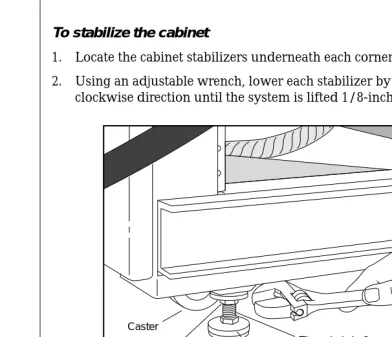
To stabilize the cabinet
1. Locate the cabinet stabilizers underneath each corner of the cabinet.
[image:33.792.135.527.174.510.2]2. Using an adjustable wrench, lower each stabilizer by rotating the locking nut in a clockwise direction until the system is lifted 1/8-inch off the casters (see Figure 2-1).
Figure 2-1. Stabilizing the cabinet
3. Turn the locking nut counterclockwise until it reaches the top of the threaded shaft, and tighten it to lock the stabilizer foot in position. Make sure the foot does not turn as you tighten the locking nut.
This completes the procedure for stabilizing the cabinet.
Opening the Cabinet Doors
The NetServer has two duplicate keys tie-wrapped to the power cable. The keys open both the front and back doors of the base cabinet. If your NetServer includes an expansion cabinet, the key also opens its front and back doors. Once the doors are unlocked, you can open and close them without a key.
Caster
Locking nut
Threaded shaft
NetServer Components
After unpacking and stabilizing the NetServer, make sure you have the following:
▲ HDDA drive drawers (one minimum) packed separately in foam-padded boxes with
disk drives pre-installed per each NetServer configuration
▲ Disk (one minimum) and CD-ROM (one minimum) drives packed separately in
foam-padded boxes for installing in the seven-slot drive rack
▲ Documentation set, including:
– NS 7000 Model 800 Series Hardware Manual(this manual)
– System Manager's Guide
– System Manager’s Quick Reference
– Command Reference Guide
– Software release note
▲ System console ▲ Modem cable ▲ Power cable
Instructions for connecting cables appear in Chapter 3, sections “Grounding the NetServer,” “Connecting the System Console to the Server,” “Attaching SCSI Devices,” and “Connecting the NetServer to the Network.”
If you ordered an expansion cabinet, make sure you have the following:
▲ Connection kit
▲ HDDA drive drawers (one minimum) packed separately in foam-padded boxes with
disk drives pre-installed per each NetServer configuration
▲ Storage Processor V ▲ 48-volt power supply ▲ Power cable
Base Cabinet Subassemblies ▲ 2-7
Base Cabinet Subassemblies
The NS 7000/800 base cabinet has the following subassemblies:
▲ 14-slot card cage chassis ▲ Seven-slot drive rack (one) ▲ HDDAs (up to two)
▲ Power distribution unit (PDU)
▲ Main power supply enclosure with one to three power supplies installed offering a
nonredundant or optional redundant configuration
▲ 8-slot bulk power chassis with up to three bulk power supplies installed for
distributing power to the HDDA drive drawers.
Figure 2-2. Base cabinet subassemblies (front view)
Card cage
EMI screen
Main power supplies Lower front
door panel Upper front door panel
7-slot drive rack
HDDA chassis 1 (standard) HDDA chassis 2 (optional) Bulk power
supplies
AC OK DC OK
Base Cabinet Subassemblies ▲ 2-9 Figure 2-3. Base cabinet subassemblies (back view)
Card cage
Main power supply enclosure
PDU Back door
panel
Wrist strap
Main power switch
8-slot bulk power supply chassis location
5 A
5 A
5 A
5 A
5 A
5 A
5 A
5 A
Expansion Cabinet Subassemblies
The expansion cabinet contains the following subassemblies:
▲ HDDAs (up to five)
▲ Power distribution unit (PDU)
▲ 8-slot bulk power chassis with up to six bulk power supplies installed for distributing
power to the HDDA drive drawers.
Expansion Cabinet Subassemblies ▲ 2-11 Figure 2-4. Expansion cabinet (front view)
System chassis Side panel Lower front door panel Upper front door panel
Figure 2-5. Expansion cabinet (back view)
PDU
Main power switch Lower front
door panel Upper front door panel
5 A
5 A
5 A
5 A
5 A
5 A
5 A
5 A
5 A
5 A
5 A
5 A
5 A
5 A
5 A
5 A
5 A
5 A
5 A
5 A
HDDA chassis 1 HDDA chassis 2 HDDA chassis 3 HDDA chassis 5
HDDA chassis 4
Card Cage Components ▲ 2-13
Card Cage Components
The NS 7000/800 card cage houses the following VME compatible printed-circuit boards:
▲ Host Processor (one)
▲ Network Processor (up to five) ▲ Storage Processor (up to five)
Each of these boards, their functions, and minimum and maximum configurations are described as follows.
HP VIII
The HP VIII has the following features:
▲ 125-MHz SPARC CPU processor
▲ Two or four memory modules of 32 to 128 MB each for up to 384 MB of host memory
(see Table 2-1).
▲ Support for up to three SBus cards (except ATM): two masters and one slave SBus
slot.
Note: The HP supports three single, one double and one single, or one triple SBus card.
▲ Serial connections to the TTYA and TTYB ports.
▲ Integrated Mbus design allowing future upgrades to the CPU. ▲ Support for up to seven SCSI devices on one SCSI port.
Table 2-1 lists the memory configurations for the HP.
Note: HP memory modules must be installed in pairs of the same capacity.
Table 2-1. HP memory configurations No. of 32-MB
memory modules
No. of 64-MB memory modules
No. of 128-MB memory modules
Total
memory (MB)
0 2 0 128
2 2 0 192
0 4 0 256
0 0 2 256
2 0 2 320
Figure 2-6 illustrates the HP front panel. DIAG READY RESET RUN DIAG NORM DIAG LEDS SCSI TTYB TTYA
SCSI port. The HP SCSI
port supports up to seven daisy-chained SCSI devices.
RESET switch. Resets the
system processor boards without power cycling the NetServer using the main power switch.
Caution: Follow the shutdown procedures described in your NetServer hardware manual before resetting or powering off the server.
TTYB serial port. The
TTYB port supports a modem or other serial device.
TTYA serial port. The
TTYA port supports the console terminal. See Chapter 5 for more information.
DIAG switch. This switch is set to NORM before powering on the NetServer.
Setting the switch to DIAG puts the NetServer in diagnostic mode automatically after powering on the system. (Provided for Auspex authorized service personnel only.)
HP fuse. Contact your authorized Auspex service representative for
replacement when needed.
DIAG LEDs. When the
NetServer is running in diagnostic mode, the state of these eight LEDs represents a specific diagnostic test running on the HP. When the operating system is running, the LEDs light in an oscillating pattern, the speed of which is determined by the CPU load— the slower the speed, the higher the load.
SBus ports. There are three
SBus ports: two masters and one slave. The HP supports three single, one double and one single, or one triple SBus card. Tape storage devices are also supported from the SBus port. Contact your Auspex service representative for more information on supported SBus cards and for installation.
Status indicator LEDs. The
Card Cage Components ▲ 2-15
NP IV
The NP IV has the following features:
▲ 128 to 256 MB of memory
▲ 100 MB-per-second VME transfer speed when operating in conjunction with SP V ▲ Support for the following network interfaces:
– 100Base-T Ethernet – ATM (fiber or UTP) – FDDI-DAS (fiber)
– FDDI-SAS (fiber or MLT-3) – Quad Ethernet
– Quad 10/100Base-T Ethernet
Note: Contact your Auspex sales representative for the latest information on supported network interfaces.
Table 2-2 lists the supported network interface configurations.
Table 2-2. Network interface configurations Number and type of network interfaces supported*
* Each Quad Ethernet SBus card has four 10Base-T Ethernet ports.
1 to 3 FDDI-SAS (fiber or MLT-3) 1 FDDI-DAS
1 to 3 100Base-T Ethernet (half or full duplex) 1 to 3 ATM (fiber or UTP)
1 to 3 Quad Ethernet
1 100Base-T Ethernet (half or full duplex), 1 Quad Ethernet 2 100Base-T Ethernet (half or full duplex), 1 Quad Ethernet 1 100Base-T Ethernet (half or full duplex), 2 Quad Ethernet 1 FDDI-SAS (fiber or MLT-3), 1 Quad Ethernet
1 FDDI-SAS (fiber or MLT-3), 2 Quad Ethernet 2 FDDI-SAS (fiber or MLT-3), 1 Quad Ethernet 1 FDDI-DAS, 1 Quad Ethernet
1 ATM, 1 Quad Ethernet 2 ATM, 1 Quad Ethernet 1 ATM, 2 Quad Ethernet 1 Quad 10/100Base-T Ethernet
Figure 2-7 shows an example of mixed network interfaces on NP boards. MII MII Label location Label location RT ahme0 ahme1 ahme2 ahme3 ahme5 ahme4 ahme6 ahme7 ahme0 afa0
aqa0 - aqa3 ael0 - ael15
ahme1 NP0 Quad 10/100Base-T Ethernet NP1 ATM NP1 Quad 10/100Base-T Ethernet ahme9 ahme8 ahme10 ahme11 NP2 Quad 10/100Base-T Ethernet
0 1 2 3 LED
0 1 2 3 LED
0 1 2 3
Card Cage Components ▲ 2-17
The NP IV supports up to 256 MB of memory for protocol, file, and I/O processing. Each NP IV has four or eight SIMMs of either 16 or 32 MB each.
Table 2-3 lists the memory configurations for the NP IV.
Note: NP SIMMs must be installed in groups of four or eight of the same capacity.
SP V
The NS 7000/800 supports up to five SP V boards. Each SP V has six SCSI channels for connecting disk, tape, and CD-ROM drives. A Write Accelerator III board, with 8 MB of memory is added to enhance NFS write operations.
The SP V has a VME transfer speed of up to 100 MB per second when operating in conjunction with NP IV.
Figure 2-8 shows a card cage configuration with system processor connections.
Figure 2-8. System processors Table 2-3. NP IV memory configurations
No. of 16-MB SIMMs No. of 32-MB SIMMs Total memory (MB)
0 4 128
4 4 192
0 8 256
SCSI connector
Host Processor
Network Processor
Processor Board Slot Assignments
This section describes slot assignments for each processor board. For information on processor board configurations, refer to Chapter 1.
Table 2-4 lists the slot allocations for each processor board.
Table 2-4. Processor board slot allocations
▲ The Host Processor board is installed in slots 1 and 2.
▲ The fourth and fifth Storage Processor boards are installed in slots 3 and 4 (numbered
SP3 and SP4 by the system software).
▲ Starting in slot 5, Network Processor boards are installed (up to five). ▲ Slot 11 is reserved for future use.
▲ Starting in slot 12, the first three Storage Processor boards are installed (numbered
SP0, SP1, and SP2 by the system software).
Note: Slots 2 and 10 are not accessible individually. Slots 5, 6, 7, and 8 are double-width slots. Slots 9 and 10 serve as the fifth double-width slot for the NP boards.
Slot
Processor board 1 2 3 4 5 6 7 8 9 10 11 12 13 14
Host Processor
Network Processor
Power Supply Configurations ▲ 2-19
Power Supply Configurations
This section describes the power supply configurations for redundant and nonredundant operation for the base cabinet and expansion cabinet main power supplies and the 48 volt bulk power supplies. The section briefly describes the Disk DCC requirement for each drive drawer.
In a redundant configuration, if one power supply fails, the remaining power supply keeps the NetServer operating. When this occurs, the failed power supply can be hot-plugged (replaced) while the server is running off the remaining supply. Power supplies can also be hot-plugged when your configuration requires additional power.
Note: Contact your authorized Auspex service representative for assistance with installing power supplies.
For more information on power subsystem operation, refer to Chapter 5.
Main Power Supplies
The base cabinet supports up to three main power supplies. These power supplies share the power requirements of the NetServer processor boards and seven-slot drive rack. The NetServer is shipped with two main power supplies for nonredundant system operation. For redundant system operation, you must add a third power supply.
Bulk Power Supplies
The bulk power supplies are located below the seven-slot drive rack in the base cabinet and below the HDDA chassis in the expansion cabinet (see Figures 2-3 through 2-5). Redundancy operation for the HDDAs is optional with bulk power supplies. Auspex ships each NetServer from the factory configured with one bulk power supply for each HDDA. When ordering additional HDDAs, you must order additional bulk power supplies.
Disk DC Converter (DCC)
Each drive drawer requires one Disk DCC converter to convert the 48-volt power
Installation ▲ 3-1
3
Installation
About This Chapter
This chapter provides the procedures for installing the NetServer components. The following sections are covered in this chapter:
▲ Grounding the NetServer
▲ Installing the Antistatic Wrist Strap ▲ Connecting the System Console ▲ Network Cable Connections ▲ Network Interface Numbering
▲ Installing Drives in the Seven-Slot Drive Rack ▲ Installing an HDDA Drive Drawer
Caution: Throughout the procedures in this chapter, when you are instructed to cut tie-wraps to free needed cables or components, remember to cut only red tie-wraps. Do not cut the black or white tie-wraps. The black and white tie-wraps hold bundles of cables together and keep them out of the way during system operation and drive installation.
Note: The NetServer is configured at the factory to match your order. Additional processor boards, memory, and drives are available as optional equipment. Contact your authorized Auspex service representative for processor board or memory installation.
Grounding the NetServer
This section provides instructions for grounding the base cabinet. You must plug in the power cable for each cabinet to create a ground path for the antistatic wrist strap.
Warning: The wiring at your site must provide for ground fault protection to prevent electric shock during installation.
Tools
▲ Knife ▲ Wire cutter
▲ 3/16-inch flat-head screwdriver ▲ 7/16-inch nut driver
▲ #2 Phillips screwdriver
To ground the NetServer
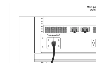
1. Locate the main power switch on the PDU in the base cabinet, and set it to OFF (O). Figure 3-1 shows the location of the main power switch in the base cabinet.
Figure 3-1. Main power switch (back view of base cabinet)
2. If you are connecting an expansion cabinet, locate the main power switch on the PDU in the expansion cabinet. Set this switch to OFF (O). Figure 3-2 shows the location of the main power switch in the expansion cabinet.
PDU
Grounding the NetServer ▲ 3-3 Figure 3-2. Main power switch (back view of expansion cabinet)
3. Locate the power cable for each cabinet.
On the base cabinet, the cable is hanging on the left side of the cabinet, secured with red tie-wraps. On the expansion cabinet, the cable is coiled on top of the panel covering the power supply.
4. Cut the red tie-wraps to release the power cable, and plug the appropriate end to the back of the PDU.
5. Tighten the strain relief surrounding the plug at the PDU.
6. After ensuring the power to the system is off, route each power cable to a separate grounded outlet, and plug it in. The outlet must be on a 20-amp circuit for the base cabinet and on a 30-amp circuit for the expansion cabinet.
Caution: Do not power on the server at this time. You connected the power cable only to provide a ground path for the antistatic wrist strap. Do not power on the NetServer until instructed to do so later in this manual.
This completes the procedure for grounding the NetServer.
Strain relief
Fuses Main power
Installing the Antistatic Wrist Strap
This section provides procedures for installing the antistatic wrist strap. To prevent electrostatic damage to the NetServer, always wear the antistatic wrist strap when you come in contact with electrostatic-sensitive equipment.
Note: The wrist strap cannot prevent electrostatic damage to system components until the NetServer power cable is plugged into a grounded power outlet.
The base cabinet and expansion cabinets have two wrist strap jacks each, one on the left chassis frame rail inside the upper front door and one on the left chassis frame rail inside the back door.
One wrist strap is provided with each cabinet. On the base cabinet, the strap is attached to the back jack. On the expansion cabinet, the strap is attached to the front jack.
1. Cut the red tie-wraps holding the wrist strap to the chassis frame rail hook.
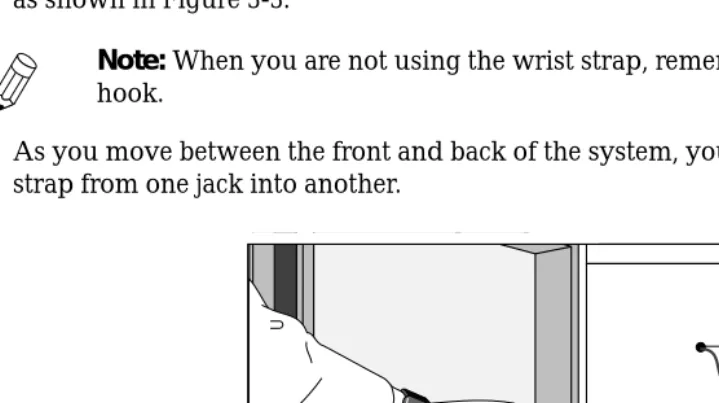
2. To use the wrist strap, remove the strap from the hook and slide it around your wrist, as shown in Figure 3-3.
Note: When you are not using the wrist strap, remember to hang it on the hook.
[image:52.792.87.447.393.594.2]3. As you move between the front and back of the system, you can unplug the wrist strap from one jack into another.
Figure 3-3. Antistatic wrist strap (back view of base cabinet)
This completes the procedure for installing the antistatic wrist strap.
Wrist strap jack
Connecting the System Console ▲ 3-5
Connecting the System Console
Each NetServer includes an ANSI-compatible system console. This section explains how to connect the system console to the NetServer. If you wish to use another type of console, contact Auspex Technical Support for compatibility information.
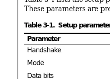
Table 3-1 lists the setup parameters for configuring the system console with the NetServer. These parameters are preconfigured for system consoles purchased from Auspex.
To connect the system console to the server
1. Remove the console and its components from the packing box.
2. Connect the keyboard and power cable to the console, as described in the console’s user manual.
Caution: Do not power on the console at this time.
3. Remove the console cable from its packing box.
4. Put on the antistatic wrist strap, and wear it throughout the procedure.
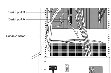
5. Route one end of the console cable through the opening in the PDU at the back of the cabinet, as shown in Figure 3-4.
[image:53.792.145.335.189.325.2]Note: In raised-floor environments, the cable can be routed through the floor panel of the NetServer. Contact your authorized Auspex service representative for assistance.
Table 3-1. Setup parameters for system consoles Parameter Value
Handshake XON/XOFF Mode Full-duplex Data bits 8
Stop bit 1
Figure 3-4. Routing cables to the NetServer
6. Connect the console cable to Serial Port A on the HP. 7. Replace the wrist strap on the back door of the base cabinet.
8. Connect the remaining end of the cable to Comm 1 on the back of the console. 9. Make sure the console power cable is properly connected to the console, and plug it
into a grounded power outlet.
Caution: Do not use the power outlets on the back of the PDU to power peripheral devices such as the console unless the console can accept the same voltage as the wall outlet. If there is a mismatch in voltage, you can damage the peripheral device.
10. Power on the system console.
This completes the procedure for connecting the system console to the NetServer.
Note: If you did not purchase your system console from Auspex, configure the console as described in Appendix C.
Serial port B
Serial port A
Power cable Console cable
Network Cable Connections ▲ 3-7
Network Cable Connections
This section is provided as a reference to show the network cable connections to ATM, Ethernet, and FDDI ports on NP boards.
Note: The FDDI-SAS port for a fiber connection is a single-attach station of “Type S.” Connect the FDDI-SAS to a “Type M” FDDI concentrator port only.
The FDDI-DAS ports are a dual-attach station. Connect directly to the primary and secondary FDDI rings or to “Type M” ports on two concentrators in a dual-homed configuration.
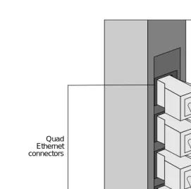
Figures 3-5 through 3-13 illustrate connections to Ethernet, FDDI and ATM ports on NP boards.
Figure 3-5. Connection to Quad 10/100Base-T Ethernet ports
Quad
Figure 3-6. Connection to Quad Ethernet ports
Quad Ethernet connectors
PORT PORT
2
Half-duplex 100Base-T Ethernet connectors
[image:56.792.151.380.376.656.2]Network Cable Connections ▲ 3-9 Figure 3-8. Connection to full-duplex 100Base-T Ethernet ports
Figure 3-9. Connection to FDDI (fiber) ports
PORT
2
Full-duplex 100Base-T Ethernet connectors
PORT
1
FDDI connectors FDDI
Figure 3-10. Connection to FDDI (MLT-3) ports
MLT-3 connectors
ATM (fiber) connectors
RT
[image:58.792.137.359.390.668.2]Network Cable Connections ▲ 3-11 Figure 3-12. Connection to ATM (UTP) ports
ATM (UTP) connectors
RT
Network Interface Numbering
Network interface numbering is used to configure the system software so it identifies each installed interface. The numbering scheme for each supported network interface is described as follows.
Quad 10/100Base-T Ethernet Quad 10/100Base-T Ethernet interfaces are numbered ahme0 to ahmen, where 0 is the lower Ethernet port closest to the HP, and n is the upper Ethernet port farthest from the HP.
Quad Ethernet Quad Ethernet interfaces are numbered aqe0 to aqen, where 0 is the lower Ethernet port closest to the HP, and n is the upper Ethernet port farthest from the HP.
Half-duplex 100Base-T Ethernet Half-duplex 100Base-T interfaces are numbered afe0 to afen, where 0 is the lower Ethernet port closest to the HP, and n is the upper Ethernet port farthest from the HP.
Full-duplex 100Base-T Ethernet Full-duplex 100Base-T interfaces are numbered ahme0 to ahmen, where 0 is the lower Ethernet port closest to the HP, and n is the upper Ethernet port farthest from the HP.
FDDI FDDI interfaces are numbered afddi0 to afddin, where 0 is the lower FDDI port closest to the HP, and n is the upper FDDI port farthest from the HP.
Note: In DAS network configurations, only one port is assigned an interface number although two ports exist on the FDDI-DAS SBus card.
ATM Each ATM port supports three types of interfaces: 1 FORE IP primary interface, 4 Classical IP virtual interfaces, and 16 LANE Client (LEC) interfaces. Refer to Table 3-2 for an example of the network numbering for these interfaces.
Table 3-2 shows an example of ATM network interface numbering on a NetServer with two NP boards (NP0, NP1), each having two ATM SBus cards (0, 1 and 2, 3).
Table 3-2. ATM network interface numbering NP board no. ATM adapter no. FORE IP primary interfaces Classical IP virtual interfaces LANE Client interfaces
Network Interface Numbering ▲ 3-13
Ethernet Addressing
Auspex assigns unique network addresses (starting with 00:00:3c) to the Ethernet ports to identify each interface. The interfaces are numbered from bottom to top.
[image:61.792.138.325.168.391.2]Table 3-3 shows an example of the Quad 10/100Base-T Ethernet addressing shown in Figure 3-13 on page 3-14.
Table 3-3. Quad 10/100Base-T Ethernet addressing Interface no. Network address
ahme11 00:00:3c:99:99:0B ahme10 00:00:3c:99:99:0A ahme9 00:00:3c:99:99:09 ahme8 00:00:3c:99:99:08 ahme7 00:00:3c:99:98:07 ahme6 00:00:3c:99:98:06 ahme5 00:00:3c:99:98:05 ahme4 00:00:3c:99:98:04 ahme3 00:00:3c:99:97:03 ahme2 00:00:3c:99:97:02 ahme1 00:00:3c:99:97:01 ahme0 00:00:3c:99:97:00*
MII MII Label location Label location RT ahme0 ahme1 ahme2 ahme3 ahme5 ahme4 ahme6 ahme7 ahme0 afa0
aqa0 - aqa3 ael0 - ael15
ahme1 NP0 Quad 10/100Base-T Ethernet NP1 ATM NP1 Quad 10/100Base-T Ethernet ahme9 ahme8 ahme10 ahme11 NP2 Quad 10/100Base-T Ethernet
0 1 2 3 LED
0 1 2 3
LED
[image:62.792.66.475.73.687.2]Installing Drives in the Seven-Slot Drive Rack ▲ 3-15
Installing Drives in the Seven-Slot Drive Rack
This section provides the procedures for installing drives in the seven-slot drive rack. For instructions on removing drives from the seven-slot drive rack, refer to Appendix A. Drive labels are shipped with the drives for recording drive numbers, as recognized by the system software. Put extra labels in a safe place; you will need them as you expand disk space. The drives and drive slots are numbered as follows:
Note: The procedures in this section assume the NetServer is powered off.
To install a drive in the seven-slot drive rack
1. Put on the antistatic wrist strap.
2. Remove the drive from its antistatic wrapping. The drive has a label located on the front of the drive carrier.
The first drive you install is the root drive which contains the system software. This drive installs in slot 0 in the drive rack. The next drive is the CD-ROM, which installs in slot 1, then any remaining drives.
3. Holding the drive by the handle and cradling it with your other hand, gently slide the drive into the drive slot until the small latch button on top of the drive carrier snaps into place. Be sure to install the root drive into slot 0. See Figure 3-14.
[image:63.792.132.516.352.697.2]Caution: Do not slam drives into the drive slots. Slamming the drives into the drive slots can cause damage to the drives and connectors.
Figure 3-14. Installing a drive in the seven-slot drive rack
Root disk ad0 Slot 0 CD-ROM acd1
Drives install in one direction only. If the drive does not slide into the drive slot easily, or the latch does not click into place, remove the drive, and try again. Make sure the drive is in the correct position, with the latch button at the top of the handle.
4. Repeat steps 2 and 3 to add additional drives.
Installing an HDDA Drive Drawer ▲ 3-17
Installing an HDDA Drive Drawer
This section describes how to install an HDDA drive drawer in the base or expansion cabinet. Drives are pre-installed in the drive drawers at the factory. To install additional loose drives in the drive drawer, refer to Appendix A.
The HDDA chassis, which hold the drive drawers, are pre-installed at the factory. The base cabinet supports up to two HDDA chassis; the expansion cabinet supports up to five HDDA chassis.
Note: This procedure assumes you understand the drive drawer and HDDA numbering as described in Appendix A. Refer to Appendix A for more information.
Tools
▲ Antistatic wrist strap ▲ 3/32 Allen wrench
Note: The procedures in this section assume the NetServer is powered off.
To install an HDDA drive drawer
1. Put on the antistatic wrist strap.
2. Identify the HDDA chassis where you will install the drive drawer.
The drive drawers are installed from left to right in the HDDA chassis, from the bottom HDDA chassis to the top HDDA chassis.
3. Locate the drive drawer handle, and insert it into the groove at the top of the drive drawer (see Figure 3-15).
Note: Only one drawer handle is required for each HDDA rack. Once
Figure 3-15. Drive drawer front panel
4. Holding the drive drawer with both hands, align the drive drawer with the side rails in the HDDA chassis, and gently slide the drive drawer halfway into the drawer slot.
Caution: Do not force the drive drawers into the slots; doing so can damage the unit.
5. While holding the handle at a 45-degree angle, slide the drawer the rest of the way into the slot until is about 3/4-inch from the HDDA chassis (see Figure 3-16).
Note: Be sure that the drawer faceplate is pulled down far enough to allow the cam lever at the bottom of the faceplate to clear the chassis. Once in position, the cam lever provides the cam action that firmly seats the drawer into the chassis once it’s closed.
Installing an HDDA Drive Drawer ▲ 3-19 Figure 3-16. Installing a drive drawer
Caution: Do not force the drive drawers into the drive drawer slots; doing so will damage the unit.
6. Push the drawer handle up so that the cam lever engages the cam slots in the HDDA chassis. See Figure 3-17.
Figure 3-17. Cam lever engaging in cam slot
Cam lever Drawer latch
Cam lever
[image:67.792.138.504.77.360.2]7. Once the cam lever is engaged in the cam slots, seat the drive drawer firmly into the drawer slot by pressing the handle closed. The caming action of closing the handle seats the drive drawer properly. See Figure 3-18.
Figure 3-18. Latching the drive drawer
The drawer latch at the top left corner of the drive drawer will click into position when the drawer is properly seated.
Caution: Do not force the drive drawers into the slots; doing so will damage the unit. If the drawer is not seating properly, move the handle to release the drawer latch, pull the drawer out, and try again.
8. Secure the drive drawer to the HDDA chassis by removing the retaining screw from the upper hole position to the lower hole position.
Drawer latch
Retaining screw
[image:68.792.62.373.121.347.2]Installing an HDDA Drive Drawer ▲ 3-21
[image:69.792.135.447.113.346.2]9. Lock the drive drawer into position by inserting the drawer key (tie-wrapped along with the base cabinet door keys) into the drive drawer lock and turn it clockwise, as shown in Figure 3-20.
Figure 3-20. Locking the drive drawer
10. Repeat steps 4 through 9 to install additional drive drawers. This completes the procedure for installing an HDDA drive drawer. To add additional drives to an HDDA drive drawer, refer to Appendix A.
Unlocked
Power On and Shut Down ▲ 4-1
4
Power On and Shut Down
About This Chapter
This chapter describes how to power on and shut down the NetServer. The following sections are covered in this chapter:
▲ Powering On the NetServer
Powering On the NetServer
Caution: Never cover the cooling vents on top of the NetServer. Covering the vents causes the NetServer to overheat and damages the server.
1. Verify the diagnostic switch on the HP is set to NORM.
The diagnostic switch is the lower of the two switches located on the front panel of the HP. Push this switch down to set it to NORM (see Figure 2-7 on page 2-14). 2. Make sure the main power switch on the base and each expansion cabinet’s PDU is
set to OFF (O) (see Figure 3-1 on page 3-2).
Caution: Use the main power switch on the PDU only.
In the NetServer, the switch located at the top of each power supply located at the front of the cabinet should always be turned to ON ( — ).
3. Close the doors on the base and expansion cabinets. 4. Power up the console terminal.
5. Power on each expansion cabinet by setting its power switch to ON ( I ).
6. Power on each tape storage device, if present, by setting its power switch to ON ( I ). 7. Power on the base cabinet by setting its main power switch to ON ( I ).
Recommendation: Auspex recommends that you power on the expansion cabinets before you power on the base cabinet. If you power on the base cabinet first, power on the expansion cabinets within 10–15 seconds after powering on the base cabinet.
After powering on the NetServer, it runs a series of self tests and displays the results of these tests on the console screen. For a list of the power-on self tests and messages, refer to section “Power-On Self Test and Boot Sequence” on page 4-3.
This concludes the procedure for powering on the NetServer.
Power-On Self Test and Boot Sequence ▲ 4-3
Power-On Self Test and Boot Sequence
The following is a sample boot message file. System messages can vary depending on the individual system configurations.
EEPROM boot device...ad(0,0,0) sp - status 70 71 f0
skipping SP loopback test
passed SP inquiry cmd to the boot device
passed SP test unit ready cmd to the boot device sp found in slot = 12
Boot device: /mvic/vme/asp@6d,1180/ad@0,0:0 File and args: 0x4000
bootblock loaded sp - status f0
skippi