Abstract—An epicycloid or hypocycloid mechanism is capable of drawing an exact epicycloid or hypocycloid curve. Similar mechanism designs can be found abundantly in industrial machines or educational equipments. Currently, the major type of epicycloid or hypocycloid configurations is planetary gear trains, which contain a binary link that has one fixed and one moving pivot, and a singular link adjacent to the moving pivot. The main feature of the configurations is that a point on the singular link may describe an epicycloid or hypocycloid curve when the binary link is rotated. The main aim of this paper is to develop a new design method in designing new configurations of planetary epicycloid (hypocycloid) mechanisms. This paper analyses the characteristics of the topological structures of existing planetary gear train type epicycloid (hypocycloid) mechanisms. The motion equations and kinematical model of the mechanism were derived and appropriate design constraints and criteria were implemented. Finally, using the design constraints and criteria, this work designs new epicycloid (hypocycloid) mechanisms.
Index Terms—epicycloids, hypocycloid, mechanism, motion equation, kinematical model.
INTRODUCTION
The hypocycloid curve produced by fixed a point P on the circumference of a small circle of radius rb rolling
around the inside of a large circle of radius ra. A 3-cusped
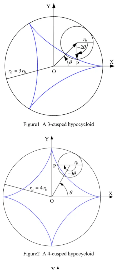
[image:1.595.323.539.647.780.2]hypocycloid shown in Figure 1 is also called a tricuspoid or deltoid [1]. The deltoid was first considered by Euler in 1745 in connection with an optical problem. It was also investigated by Steiner in 1856 and is sometimes called Steiner's hypocycloid [2]. A 4-cusped hypocycloid shown in Figure 2 is sometimes also called a tetracuspid, cubocycloid, paracycle, or asteroid [3]. The parametric equations of the deltoid and astroid can be obtained by plugging in
3 / = =ra rb
n and n=ra/rb =4 into the equations for a general hypocycloid, respectively.
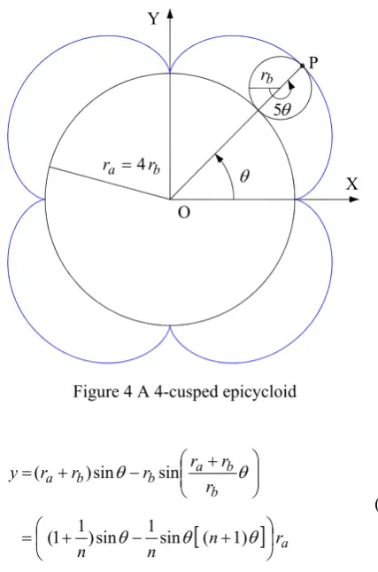
The epicycloids path traced out by a point P on the edge of a circle of radius rb rolling on the outside of a circle of
radius rA [4]. To get n cusps in the epicycloid, n=ra/rb,
because then n rotations of rb bring the point on the edge
back to its starting position. An epicycloid with one cusp is called a cardioid, one with two cusps is called a nephroid, and one with five cusps is called a ranunculoid. Figure 3 and 4 show a 3-cusped and a 4-cusped epicycloid, respectively.
An exact hypocycloid (epicycloids) curve can be also produced by using a hypocycloid (epicycloids) mechanism.
Meng-Hui Hsu is the corresponding author and now with Department of Mechanical Engineering, Kun Shan University, Yung Kang 71003, Tainan, TAIWAN (phone: +886-6-205-0761/0730; fax: +886-6-205-0509; e-mail: [email protected]). .
Similar mechanism designs can be found abundantly in industrial machines. Currently, the major type of epicycloid or hypocycloid configurations is planetary gear trains [5], which contain a binary link that has one fixed and one moving pivot, and a singular link adjacent to the moving pivot. The main feature of the configurations is that a point on the singular link may describe an epicycloid or hypocycloid curve when the binary link is rotated.
This paper will analyses the characteristics of the topological structures of existing planetary gear train type epicycloid (hypocycloid) mechanisms with one degree of freedom. The equation of motion and kinematic model of the mechanism could be derived and appropriate design constraints and criteria were implemented. Subsequently, using the design constraints and criteria, this work can design a new epicycloid (hypocycloid) mechanism.
NOMENCLATURE n Radius ratio, n=ra/rb n′ Link length ratio, n′=rc /rb
i
r Radius or length of member i i
T Number of teeth of gear i
x,y X and Y-coordinate of an epicycloid (hypocycloid) θ Angular displacement of driving member (the center
of small circle., carrier, or binary link)
i
ω Angular velocity of member i
HYPOCYCLOID
The hypocycloid curve produced by fixed point P on the circumference of a small circle of radius rb rolling around
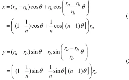
the inside of a large circle of radius ra. The Cartesian
parametric equations of the hypocycloid, path of point P, are:
[
]
a bb a b b
a
r n
n n
r r r r r
r x
⎟ ⎠ ⎞ ⎜
⎝
⎛ − + −
=
⎟⎟ ⎠ ⎞ ⎜⎜
⎝ ⎛ − +
− =
θ θ
θ θ
1) ( cos 1 cos ) 1 1 (
cos cos
) (
(1)
[
]
a bb a b b
a
r n
n n
r r r r r
r y
⎟ ⎠ ⎞ ⎜
⎝
⎛ − − −
=
⎟⎟ ⎠ ⎞ ⎜⎜
⎝ ⎛ − −
− =
θ θ
θ
θ θ
1) ( sin 1 sin ) 1 1 (
sin sin
) (
(2)
Planetary Hypocycloid (Epicycloid)
Mechanisms Design
Where n=ra/rb is radius ratio, θ is the angular displacement of the center of small circle. n-cusped hypocycloids can also be constructed by beginning with the diameter of a circle, offsetting one end by a series of steps while at the same time offsetting the other end by steps
) 1
(n− times as large in the opposite direction and extending beyond the edge of the circle. After traveling around the circle once, an n-cusped hypocycloid is produced.
The equation of the 3-cusped hypocycloid is obtained by setting n=ra/rb =3 in the equation of the hypocycloid, where ra is the radius of the large fixed circle and rb is the
radius of the small rolling circle, yielding the parametric equations:
a
r x=⎢⎣⎡ θ+ cos2θ⎥⎦⎤
3 1 cos 3
2 (3)
a
r y=⎢⎣⎡ θ− sin2θ⎥⎦⎤
3 1 sin 3
2 (4)
The parametric equations of the 4-cusped hypocycloid can be obtained by plugging in n=ra/rb=4 into the equations for a general hypocycloid, giving parametric equations:
a
r x=⎢⎣⎡ θ+ cos3θ⎥⎦⎤
4 1 cos 4 3
(5)
a
r y=⎢⎣⎡ θ− sin3θ⎥⎦⎤
4 1 sin 4
3 (6)
The following tables summarizes the names given to this and other hypocycloids with special integer values of
b a r
r
[image:2.595.315.534.51.563.2]n= / [2-4].
Table 1 Hypocycloids with special integer values of n
b a r
r
n= / Hypocycloid
2 line segment (Tusi couple)
3 deltoid 4 astroid
EPICYCLOID
The epicycloid path traced out by a point P on the edge of a circle of radius rb rolling on the outside of a circle of radius ra. Epicycloids are given by the parametric equations:
[
]
a bb a b b
a
r n
n n
r r r r r
r x
⎟ ⎠ ⎞ ⎜
⎝
⎛ + − +
=
⎟⎟ ⎠ ⎞ ⎜⎜
⎝ ⎛ + −
+ =
θ θ
θ θ
1) ( cos 1 cos ) 1 1 (
cos cos
) (
(7)
Figure1 A 3-cusped hypocycloid
Figure2 A 4-cusped hypocycloid
Figure 3 A 3-cusped epicycloid b
a r
r =4
b
r
θ θ 3 − P
X Y
O b
a r
r =3
b
r
θ θ 2 −
P X
Y
O
X b
a r
r =3
b
r
θ θ 4 Y
O
Figure 4 A 4-cusped epicycloid
[
]
a bb a b b
a
r n
n n
r r r r r
r y
⎟ ⎠ ⎞ ⎜
⎝
⎛ + − +
=
⎟⎟ ⎠ ⎞ ⎜⎜
⎝ ⎛ + −
+ =
θ θ
θ
θ θ
1) ( sin 1 sin ) 1 1 (
sin sin
) (
(8)
Where θ is the angular displacement of the center of small circle. To get n cusps in the epicycloid, rb=ra/n, because then n rotations of rb bring the point on the edge back to its starting position. An epicycloid with one cusp is called a cardioid, one with two cusps is called a nephroid, and one with five cusps is called a ranunculoid.
The equation of the 3-cusped epicycloid is obtained by setting n=ra/rb=3 in the equation of the epicycloid, where ra is the radius of the large fixed circle and rb is the radius of the small rolling circle, yielding the parametric equations:
a
r x=⎢⎣⎡ θ− cos4θ⎥⎦⎤
3 1 cos 3
4 (9)
a
r y=⎢⎣⎡ θ− sin4θ⎥⎦⎤
3 1 sin 3 4
(10)
The parametric equations of the 4-cusped epicycloid can be obtained by plugging in n=ra/rb =4 into the equations for a general epicycloid, giving parametric equations:
a
r x=⎢⎣⎡ θ− cos5θ⎥⎦⎤
4 1 cos 4
5 (11)
a
r y=⎢⎣⎡ θ− sin5θ⎥⎦⎤
4 1 sin 4 5
(12)
The following tables summarizes the names given to this and other epicycloid with special integer values of
b a r
r
n= / [2-4].
Table 2 Epicycloids with special integer values of n
b a r
r
n= / Epicycloid
1 cardioid 2 nephroid 5 ranunculoid
HYPOCYCLOID AND EPICYCLOID DESIGN CRITERIA
A. Motion equations of the planetary hypocycloid
A hypocycloid mechanism with simple planetary gear train comprises a fixed ring gear, a , a planetary gear, b, and a planetary carrier,c. In a 3-cusped hypocycloid planetary gear system, Figure 5, the number of teeth in ring gear a is
a
T , which is thrice that of gear b, i.e., Ta =3Tb. When the carrier, c, acts as the input link and rotates one revolution, a fixed point, P, on the pitch circle of gear b will describe a hypocycloid path.
The angular velocity of gear b is ωb and that of the carrier is ωc. The fixed ring gear a has a angular velocity
0 = a
ω and the relationship among the three angular velocities is [6]:
b a a
b
T T = − −
c c
ω ω
ω ω
(13) Substitutingωa =0 and Ta =3Tb into Equation (13) and
recasting: c
b ω
ω =−2 (14)
Similarly, in a n-cusped hypocycloid planetary gear system, the Cartesian parametric equations of the hypocycloid are Equations (1) and (2), the relationship among the three angular velocities is:
n r
r r r r T T
b b c b a b a c a
c
b = = = + =
− −
ω ω
ω ω
(15) and we have:
c c
b n ω nω
ω =−( −1) =− ′ (16)
1 − = =
′ n
r r n
b
c (17)
Where n′is link length ratio. From Equations (16) and (17), it is clear that the final planetary gear,b which is mounted at the end of the carrier, has an angular velocity of the
) 1 ( − = ′ n
n multiples as the carrier but at an opposite direction. A 4-cusped hypocycloid planetary gear system can be obtained and shown in Figure 6 by plugging in
4
/ =
=ra rb
n into the Equations (15), (16), and (17). X
b a r
r =4
b
r
θ θ 5 Y
O
B. Motion equations of the planetary epicycloid
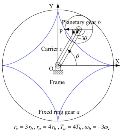
An epicycloids mechanism with simple planetary gear train comprises a fixed sun gear, a , a planetary gear, b, and a planetary carrier,c. In a 3-cusped epicycloid planetary gear system, Figure 7, the number of teeth in sun gear a is Ta, which is thrice that of gear b, i.e., Ta =3Tb. When the carrier, c, acts as the input link and rotates one revolution, a fixed point, P, on on the pitch circle of gear gear b will describe an epicycloid path.
The angular velocity of gear b is ωb and that of the
carrier is ωc. The fixed sun gear a has a angular velocity
0 = a
ω and the relationship among the three angular velocities is [6]:
b a a
b
T T − = − −
c c
ω ω
ω ω
(18)
Substitutingωa =0 and Ta =3Tb into Equation (18) and recasting:
c b ω
ω =4 (19)
Similarly, in a n-cusped epicycloid planetary gear system, the Cartesian parametric equations of the epicycloid are Equations (7) and (8), the relationship among the three angular velocities is:
n r
r r r r T T
b b c b a b a c a
c
b =− =− =− − =−
− − ω ω
ω ω
(20) and we have:
c
b n ω
ω =( +1) (21)
1 + = =
′ n
r r n
b
c (22)
From Equations (21) and (22), it is clear that the final planetary gear, b which is mounted at the end of the carrier, has an angular velocity of the n′=n+1 multiples as the carrier but at a uniform direction. A 4-cusped epicycloid planetary gear system can be obtained and shown in Figure 8 by plugging in n=4into the Equations (20), (21), and (22).
b c r
[image:4.595.322.523.55.273.2]r =2 ,ra =3rb,Ta =3Tb,ωb=−2ωc Figure 5 A 3-cusped hypocycloid mechanism
b c r
r =3 ,ra =4rb,Ta=4Tb,ωb=−3ωc Figure 6 A 4-cusped hypocycloid mechanism
b a r
[image:4.595.322.525.310.537.2]r =3 ,rc =4rb,Tc =3Tb,ωb=4ωa
Figure 7 A 3-cusped epicycloid mechanism
b a r
r =4 ,rc =5rb,Tc=4Tb,ωb=5ωa Figure 8 A 4-cusped epicycloid mechanism X
θ 2 − θ P O
Fixed ring gear a Frame
Carrier c
Planetary gear b Y
X θ
3 −
θ P
O
Fixed ring gear a Frame Carrier c
Planetary gear b Y
θ 4
θ
P
X
Fixed sun gear a Frame Carrier c
Planetary gear b Y
O
θ 5
θ
P
X
Fixed sun gear a Frame Carrier c
Planetary gear b Y
[image:4.595.47.282.372.467.2] [image:4.595.68.274.553.769.2]C. Design criteria of hypocycloid (epicycloid) mechanisms
Let us summarize the main points that have been made in this section. As Equations (15) to (17), Equations (20) to (22), Figures 5, 6, 7, and 8 indicate:
(1). A hypocycloid (epicycloids) mechanism contains a binary link (carrier) that has one fixed and one moving pivot, a singular link (planetary gear) adjacent to the moving pivot, and a frame. (2). In a planetary hypocycloid system, the singular
link has the n′=(n−1) multiples angular velocity as the binary link but rotates at an opposite direction.
(3). In an epicycloid system, the singular link has the )
1 ( + = ′ n
n multiples angular velocity as the binary link but rotates at an uniform direction. (4). The main feature of a hypocycloid (epicycloid)
mechanism is that a fixed point P on the singular link may describe an a hypocycloid (epicycloid) when the binary link is rotated.
The first three important points are design criteria (1) to (3).
They are helpful to design a new a hypocycloid (epicycloid) mechanism.
KINEMATIC MODEL OF HYPOCYCLOID
AND EPICYCLOID MECHANISMS
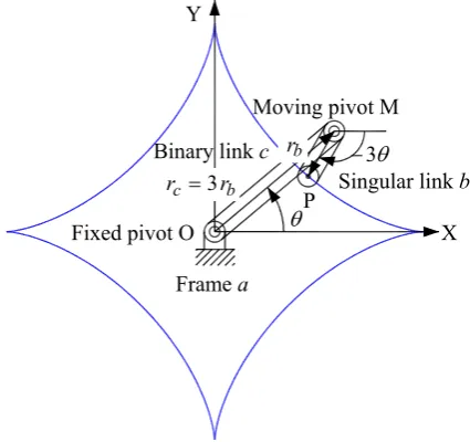
The design criterion (1) can be described as shown in Figures 9, 10, 11, and 12. They are hypocycloid and epicycloid mechanisms contain a binary link c that has one fixed and one moving pivot, a singular link b adjacent to the moving pivot, and a frame.
The design criterion (2) is the kinematic constraint of a hypocycloid mechanism and mathematically described as follows:
c c
b n ω nω
ω =−( −1) =− ′ (23)
1 − = =
′ n
r r n
b
c (24)
Where ωc and ωbare the angular velocities of binary link c and singular link b, respectively. If the initial angular positions of binary link c and singular link b are zeros, we have:
θ θ
θb=−n′ =−(n−1) (25)
Where θ and θb are the angular displacements of binary link c and singular link b, respectively. If rc and rb are the lengths of binary link c and singular link b, respectively, the coordinates x and y of point P on the singular link b are:
⎟⎟ ⎠ ⎞ ⎜⎜ ⎝ ⎛ +
= θ θ
b c b
c r rr
r
x cos cos (26)
⎟⎟ ⎠ ⎞ ⎜⎜ ⎝ ⎛ −
= θ θ
b c b
c r rr
r
[image:5.595.311.535.51.259.2]y sin sin (27)
[image:5.595.323.536.295.495.2]Figure 9 A schematic diagram of a three links linage for drawing a 3-cusped hypocycloid curve
[image:5.595.318.536.528.740.2]Figure 10 A schematic diagram of a three links linage for drawing a 4-cusped hypocycloid curve
Figure 11 A schematic diagram of a three linage for drawing a 3-cusped epicycloid curve
X Fixed pivot O
θ 2 −
θ P
Frame a
Singular link b Binary link cMoving pivot M
b c r r =2
b r
X Fixed pivot O
θ 3 −
θP
Frame a
Singular link b Binary link c
Moving pivot M
b c r r =3
b r Y
Fixed pivot O
θ 4
θ P X
Frame a
Singular link b Y
Binary link c
Moving pivot M b c r
r =4 rb
Figure 12 A schematic diagram of a three linage for drawing a 4-cusped epicycloid curve
The design criterion (3) is the kinematic constraint of an epicycloid mechanism and mathematically described as follows:
c c b n ω nω
ω =( +1) = ′ (28)
1 + = = ′ n r r n b
c (29)
Where ωc and ωbare the angular velocities of binary link c and singular link b, respectively. If the initial angular positions of binary link c and singular link b are zeros, we have:
θ θ
θb=n′ =(n+1) (30)
Where θ and θb are the angular displacements of binary link c and singular link b, respectively. If rc and rb are the lengths of binary link c and singular link b, respectively, the coordinates x and y of point P on the singular link b are:
⎟⎟ ⎠ ⎞ ⎜⎜ ⎝ ⎛ −
= θ θ
b c b c r r r r
x cos cos (31)
⎟⎟ ⎠ ⎞ ⎜⎜ ⎝ ⎛ −
= θ θ
b c b c r r r r
y sin sin (32)
NEW HYPOCYCLOID AND EPICYCLOID MECHANISMS The design criteria (1) shows the hypocycloid and epicycloid mechanism at least has three links; frame, a binary link, and a singular link. Hence, if the singular link has
) 1 ( − = ′ n
n multiples angular velocity as the binary link but rotates at an opposite direction, the mechanism can describe a hypocycloid curve. If the singular link has n′=(n+1) multiples angular velocity as the binary link but rotates at an uniform direction. The mechanism will be describe an epicycloids curve.
Based on the design constraints of the topological structure and kinematic characteristics of a hypocycloid (epicycloid) mechanism, a planetary gear train could be designed as a hypocycloid (epicycloid) mechanism.
zExample 1:Newn-cuspedhypocycloidmechanisms design
From the design requirements, a planetary gear train with one degree of freedom as shown in Figure 13 can be individualized as a n-cusped hypocycloid and the planetary gear B could be the final planetary gear. For this system, the following relationships are established:
C B B C T T = − − arm arm ω ω ω ω (33) C B B C T T ′ ′ ′ ′ = − − arm arm ω ω ω ω (34)
Where Tiis the number of teeth of gear i. From the design constraints on the kinematic characteristics, it is known that:
arm B
B ω n ω
ω ′= =−( −1) (35)
If the ring gearsCand C′are fixed, then we have: 0
= = C′ C ω
ω (36)
Rearranging Equations (29) to (30), the relationship between the tooth number of gear B, TB and ring gear C,
C
T , can be obtained as: B
C nT
T = (37)
Similarly, the relationship between the tooth number of gear B′, TB′ and ring gear C′, TC′, can be obtained as:
B C nT
T ′= ′ (38)
Furthermore, based on the relationship of the tooth numbers between the sun gear, planetary gear, and ring gear, we have TC =nTB =TC′=nTB′.
[image:6.595.66.276.47.249.2]Finally, we know the planetary gear train as shown in Figure 13 will be a n-cusped hypocycloid mechanism, if the tooth numbers of gear B, B′, C, and C′ could be satisfied with the facts TC =nTB=TC′=nTB′. It is evident that the
mechanism is an assemblage of two simple planetary gear trains. When the carrier makes a full rotation, the arbitrary points P on the pitch circle of the planetary gears B or B′ describes a n-cusped hypocycloid curve. The results of the designed 3-cusped and 4-cusped hypocycloid mechanisms are shown as Figure 14 and 15, respectively.
zExample 2: New n-cusped epicycloid mechanisms design
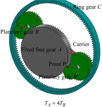
From the design requirements, a planetary gear train with two degrees of freedom as shown in Figure 16 can be individualized as a n-cusped epicycloid mechanism and the planetary gear Bcould be the final planetary gear. For this system, the following relationships are established:
⎟⎟ ⎠ ⎞ ⎜⎜ ⎝ ⎛ + ⎟⎟ ⎠ ⎞ ⎜⎜ ⎝ ⎛ − = − − ′ B C A B C A T T T T arm arm ω ω ω ω (39) ⎟⎟ ⎠ ⎞ ⎜⎜ ⎝ ⎛ + = − − ′ ′ B C C B T T arm arm ω ω ω ω (40) Fixed pivot O
θ 5 θ
P
X
Frame a
Singular link b Y
Binary link c Moving pivot M
b c r r =5
Figure 13 A planetary gear train with 1 degree of freedom
B C B
C T T T
[image:7.595.63.273.48.288.2]T =3 = ′ =3 ′
Figure 14 Anew3-cuspedhypocycloidmechanism
B C B
C T T T
[image:7.595.82.284.329.541.2]T =4 = ′=4 ′
Figure 15 Anew4-cuspedhypocycloidmechanism
Where Tiis the number of teeth of gear i.From the design constraints on the kinematic characteristics, it is known that:
arm B
B ω n ω
ω ′= =( +1) (41)
If he the sun gear A is fixed, then we have: 0
= A
ω (42)
Rearranging Equations (39) to (40), the relationship between the tooth number of gear A, TA and ring gear B,
B
T , can be obtained as: B
A nT
T = (43)
If he the ring gear Cis fixed, then we have: 0
= C
ω (44)
Rearranging Equations (39) to (40), we can’t find the feasible relationship between the tooth number of gears A,
B′, B, and C.
[image:7.595.326.498.545.767.2]Finally, we know the planetary gear train as shown in Figure 16 will be a n-cusped epicycloid mechanism, the tooth number of gear B, TB and sun gear A, TA is TA=nTB. When the arm makes a full rotation, the arbitrary points P on the pitch circle of the planetary gear B describes a n -cusped epicycloid curve. The results of the designed 3-cusped and 4-cusped epicycloid mechanisms are shown as Figure 17 and 18, respectively.
CONCLUSION
This paper analyses the characteristics of the topological structures of existing planetary gear train type hypocycloid and epicycloid mechanisms with one degree of freedom. The equation of motion of the mechanism was derived and appropriate design constraints were implemented. Subsequently, using the design constraints, this work designs one new hypocycloid and one new epicycloid mechanism. Finally, we know the methods of the proposed hypocycloid and epicycloid mechanism design is easily done.
Figure 16 A planetary gear train with 2 degrees of freedom C′
gear ring Fixed
B′ gear Planetary B
gear Planetary
C gear ring Fixed
Carrier
C′ gear ring Fixed
B′ gear Planetary B
gear Planetary
C gear ring Fixed
Carrier
P Point
C′ gear ring Fixed
B′ gear Planetary B
gear Planetary
C gear ring Fixed
Carrier
P Point
Carrier B′ gear Planetary
A gear Sun
B gear Planetary
[image:7.595.65.423.563.774.2]B A T T =3
Figure 17 A new 3-cusped epicycloid mechanism
B A T T =4
Figure 18 A new 4-cusped epicycloid mechanism
ACKNOWLEDGMENT
The authors would like to thank the National Science Institute for their support of this study through grant NSC 94-2524-S-006-002.
REFERENCE
[1] Coxeter, H. S. M. and Greitzer, S. L. Geometry Revisited. Washington, DC: Math. Assoc. Amer., p. 44, 1967.
[2] MathWorld. “Deltoid.” http://mathworld.wolfram.com/ Deltoidhtml.
[3] MathWorld. “Astroid.” http://mathworld.wolfram.com/ Astroid.html.
[4] MathWorld. “Epicycloid.” http://mathworld.wolfram. com/Epicycloid.html.
[5] Artobolevskii, I. I., Mechanisms in Modern Engineering Design, English Transaction, Mir Publishers, 1977. [6] Wilson, C. E. and Sadler, J. P., Kinematics and
Dynamics of Machinery, Harper Collins, 1993. Carrier
B′ gear Planetary A
gear Sun Fixed
B gear
Planetary Ringgear C
P Point
Carrier
B′ gear Planetary
A gear Sun Fixed
B gear Planetary
C gear Ring
[image:8.595.72.250.307.492.2]