1 INTRODUCTION
Dynamic soil-structure interaction is a pivotal aspect of the design process for large scale wind turbine design. These dynamically sensitive structures require accurate soil stiffness assessments in order to en-sure that the design frequency matches the actual operational frequency when the structures are con-structed. The reason for this is that wind turbines, unlike most large scale civil engineering structures, are subjected to periodic excitation as part of their operation. This excitation arises due to the rotor spin-ning at a given rotational velocity which induces a gyroscopic effect on the structure that is known as the 1P frequency. In addition to this, the effect of a standard turbine having three blades induces a further excitation due to the blades passing the tower. This is known as the 3P frequency. The system stiffness must be such that the natural frequency of the wind turbine does not lie within the rotor frequency exci-tation bands, as this may induce resonance which could lower the design life significantly. There are three design options available. The first involves designing the system to have a frequency lower than the 1P band, known as the soft-soft option (Tempel & Molenaar, 2002). This is difficult in offshore con-ditions due to the presence of waves inducing low frequency resonances in the structure lower than the 1P band, and therefore it is often more suited to onshore turbine design. The second option involves de-signing the system so that its natural frequency resides between the 1P and 3P bands. This is known as the soft-stiff design option and is the most common. The third option involves designing a very stiff structure that has a system frequency above the 3P band. This is not so common due to the amount of material required to ensure a high stiffness. In order to combat growing energy needs, more and more
Dynamic soil-structure interaction modeling using stiffness derived
from in-situ Cone Penetration Tests
L. J. Prendergast, K. Gavin & D. Igoe
University College Dublin, Dublin, IrelandABSTRACT: This paper presents the results of an experimental and numerical investigation into the natural frequency of a pile driven into dense sand. The experimental arrangement involves fitting ac-celerometers along the pile shaft and using a modal hammer to induce lateral vibration. The natural fre-quency is obtained by performing Fourier analysis on the acceleration signals. A numerical model is developed that models the pile as a beam supported by lateral springs. The natural frequency is ob-tained by performing an eigenvalue analysis in the numerical model. The spring stiffness is derived by first obtaining the G0 value for the sand at the installation location. This is achieved using the rigidity
index, a correlation between the cone tip resistance qc value and the small-strain shear modulus G0. The
G0 value is converted to lateral spring stiffness values using an equation derived analytically from the
beam on an elastic foundation case. Good agreement is observed between the experimentally measured natural frequency and that which is calculated from the numerical model. This research paves the way for more accurate assessments of dynamic soil-structure interaction, and can be particularly useful in the design of structures that are dynamically sensitive such as wind turbines.
wind-farms are being constructed in deeper waters offshore. Over 75% of wind turbines have monopiled foundations (Doherty & Gavin, 2012). The design of these monopiles is often undertaken using Ameri-can Petroleum Institute (API) design codes from the offshore engineering industry (API, 2007). The nat-ural frequency of a wind turbine is a function of the material properties used in its construction, and is highly affected by the stiffness of the soil surrounding the monopile. As such, the accurate assessment of this stiffness in terms of modeling for the design process is very important in ensuring that the system frequency can be reliably estimated.
The API method has been shown to be conservative, particularly in the case of stiff piles (Doherty & Gavin, 2012; LeBlanc et al, 2010). The dynamic stiffness is normally taken as the initial slope of the soil reaction – displacement (P-Y) curve derived from the API method (API, 2007). This is used in the mod-eling process by idealizing the pile as a beam supported by linear springs, known as the Winkler hypoth-esis (Dutta & Roy, 2002). This idealization is known to yield reasonably good performance and is rela-tively straightforward to implement as part of a modeling regime. The stiffness values obtained from the API method are based on a number of simplified soil properties for the site and typically only require knowledge of the angle of internal friction (Φ’) and the relative density (Dr). The stiffness profile with
depth is linearly increasing for strata with uniform Φ and Dr. In reality, the stiffness of the soil for
dy-namic applications will not be as simple as those proposed by the API method. Soil is often highly het-erogeneous from point to point. The use of site investigations can provide more insight into the variable properties of soil at different locations in a stratum.
In this paper, a method to obtain more accurate soil stiffness estimations based on Cone Penetration Test (CPT) data is described and an experimental validation is detailed. Stiffness profiles are derived from CPT data by linking the small-strain shear modulus (G0) to the CPT tip resistance (qc). Known as
the rigidity index, the variation of G0/qc with qc,1 for a range of sands was investigated by (Robertson,
1997; Schnaid et al, 2004). The G0 profile that is obtained from this correlation is used to form discrete
spring stiffness values for use in a numerical model of a pile embedded in sand. The research paves the way for more accurate assessments of soil stiffness at installation locations for wind turbine foundations. 2 TEST SITE
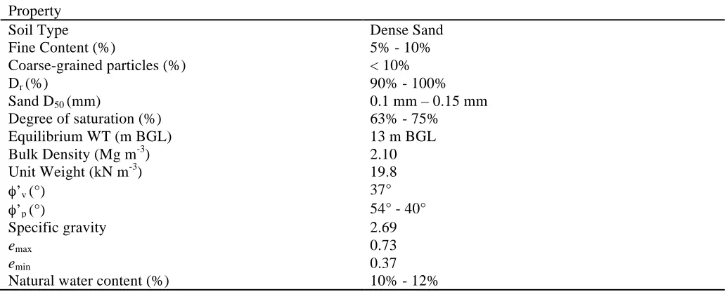
[image:2.612.48.565.519.727.2]The test bed is a dense sand quarry located in Blessington, south-west of Dublin city, Ireland. The site conditions comprise of very dense, fine sand, with a relative density between 90 – 100%. The ge-otechnical properties of the site are outlined in Table 1.
Table 1 Site Properties
Property
Soil Type Dense Sand
Fine Content (%) 5% - 10%
Coarse-grained particles (%) < 10%
Dr (%) 90% - 100%
Sand D50 (mm) 0.1 mm – 0.15 mm
Degree of saturation (%) 63% - 75%
Equilibrium WT (m BGL) 13 m BGL
Bulk Density (Mg m-3) 2.10
Unit Weight (kN m-3) 19.8
φ’v (°) 37°
φ’p (°) 54° - 40°
Specific gravity 2.69
emax 0.73
emin 0.37
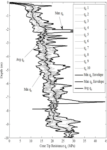
Ten CPT tests were performed at the site. The values were relatively consistent, which reveals a uni-form sand deposit where qc increased from ≈ 10 MPa at ground level to ≈ 17 MPa at 2 m below ground
[image:3.612.66.431.137.645.2]level, and increases gradually with depth thereafter. The CPT profiles are shown in Figure 1.
Figure 1. Ten cone penetration tests for Blessington site with min & max envelopes.
The average CPT profile from Figure 1 is used to derive spring stiffness values for a numerical model of an installed pile at the test location.
0 5 10 15 20 25 30 35 40 45
-10 -9 -8 -7 -6 -5 -4 -3 -2 -1 0
Cone Tip Resistance qc (MPa)
D
ept
h
(m
)
qc 1
qc 2
qc 3
qc 4
qc 5
qc 6
qc 7
qc 8
qc 9
qc 10
Min qc Envelope
Max qc Envelope
Avg qc
Max qc
Min qc
3 FIELD INSTALLATION & VIBRATION TEST
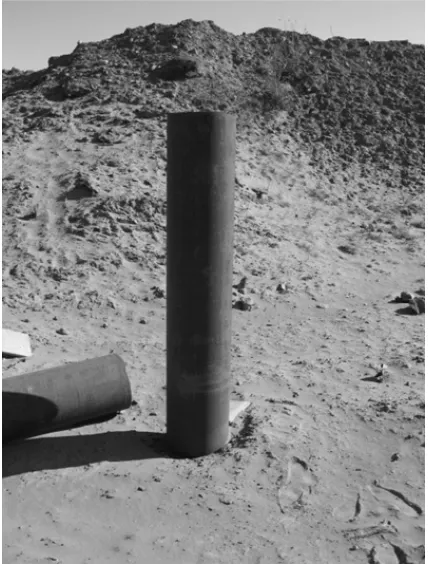
An open-ended steel pile was driven into the stratum at the test site. The pile had a length of 8.76 m, a diameter of 0.34 m and an annular thickness of 13 mm. The Young’s modulus is taken as 2 x 10¹¹ N m-2 and the cross-sectional moment of inertia is 1.91 x 10⁻⁴ m4.The pile was embedded 6.5 m when the vi-bration test was undertaken. An image of the embedded pile is shown in Figure 2.
Figure 2. Installed pile at test location.
[image:4.612.60.274.165.448.2]The vibration test involved impacting the pile head with a modal hammer that was calibrated to excite low frequency resonances in the pile. This was achieved by using a heavy tip mass with a soft impact head on the modal hammer. The resulting lateral vibration was picked up by three accelerometers em-bedded in the shaft of the pile along the exposed length. The vibration was transformed from the time-domain acceleration signal to the frequency time-domain by applying a Fourier transform in MATLAB. Five impact tests were performed. The results of the vibration test are shown in Table 2.
Table 1 Frequency Values from Test
1st Frequency (Hz) Standard Deviation (Hz)
4 SOIL-STRUCTURE DYNAMIC INTERACTION MODEL
A numerical model is developed that incorporates the dynamic soil-structure interaction by modeling the pile-soil system as a beam on an elastic foundation, commonly referred to as the Winkler hypothesis (Dutta & Roy, 2002). The pile is modeled using Euler-Bernoulli beam elements, while the soil is mod-eled by attaching a linear spring to one of each of the embedded beam nodes. The mass and stiffness ma-trices for the beam-type elements can be found in (Tedesco et al, 1999). The numerical model is capable of calculating the natural frequencies of the soil-structure system, by obtaining the eigenvalues of the system matrix as defined in the following Equation 1.
] [ ] [ ]
[D = M −1 K (1)
where [D] is the system matrix, [M] is the global mass matrix, and [K] is the global stiffness matrix for the combined soil-structure model. The eigenvalues were obtained by using MATLAB’s in-built eig function and sorting the entries in descending order to obtain the fundamental frequency.
The stiffness component of the soil is obtained by manipulating the CPT qc profile and discretizing it
into individual spring moduli. The first step involves converting the qcprofile into a small-strain shear
modulus (G0) profile using the rigidity index, a correlation between G0 and qc which was undertaken for
a range of sands (Lunne et al., 1997; Schnaid et al., 2004). Dense sand has a rigidity index which varies between 5 and 8. For the purpose of our analysis, a value of 6 was chosen for each of the springs. Varia-tion of the rigidity index with qc,1 was not considered in the analysis. The next step involves converting
the G0 profile to a Young’s modulus (E0)profile using the well-known relation shown in Equation 2.
( )
v GE0 =2 0 1+ (2)
where v is the small-strain Poisson ratio. A value of 0.1 was chosen for this parameter. Once completed, the modulus of subgrade reaction (K) profile can be obtained using a formula that couples the material properties of the soil and the pile in the elastic continuum problem. This is available in Ashford & Juirnarongrit (2003) and is shown in Equation 3.
(3)
where D is the pile diameter (m), Ep is the Young’s modulus of the pile (N m-2) and Ip is the moment of
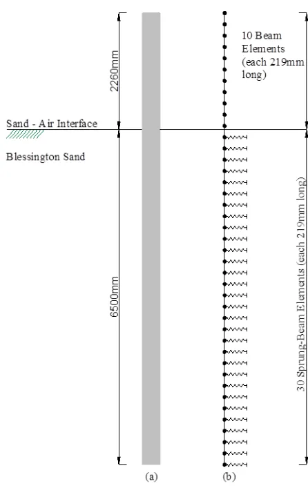
inertia of the pile cross-section (m4). Individual spring constants are obtained by multiplying the K value at a given spring depth by the spacing between subsequent springs. The model is used to perform an ei-genvalue analysis and obtain the natural frequencies corresponding to those of the soil structure system. Our numerical model contains 30 springs, each spaced at 0.219 m giving a total depth of embedment of 6.57m closing approximating the depth of embedment of our field pile. This is shown in Figure 3. The average CPT qc resistance from Figure 1 was used to obtain spring constants. The results of the
ei-genvalue analyses are shown in Table 3. The stiffness profiles adopted in this paper are shown in Figure 4 for the CPT and API springs.
Figure 3. Numerical model schematic.
Table 2 Experimental & Numerical Frequencies
Method: Avg Experimental Frequency
(Hz)
Numerical Frequency (Hz)
% Difference
CPT Springs 31.09 28.00 9.93%
API Springs 31.09 22.50 27.6%
Figure 4. Numerical stiffness profiles.
5 CONCLUSIONS
An experimental investigation into the natural frequency of a pile embedded in dense sand was under-taken at a test site in Blessington, Ireland. A numerical model was developed that models the pile em-bedded in sand as a beam supported by linear springs. The stiffness moduli of the springs were obtained using a correlation between the CPT qc profile and the small strain shear modulus (G0) for the site.
Known as the rigidity index, this allows for the G0 value to be estimated based on in-situ CPT
measure-ments. The G0 profile was converted to a modulus of subgrade reaction profile and thence to individual
spring constants for use in the numerical model. The natural frequencies obtained from the experiment and the numerical model were compared. For comparison, spring stiffness values were also generated using the API design code. It was shown that the discrepancy between the numerical model employing CPT springs and the experiment was 9.93 % whereas the discrepancy between the experiment and the numerical model employing API springs was 27.6 %. Some of the error in the experiment will be due to spectral resolution when transforming the time domain signals to the frequency domain and arises due to issues with signal length and noise presence.
While the very small strains induced by dynamically exciting the pile with the modal hammer may justify the use of the small strain shear modulus, G0, the effect of pile installation on the in-situ G0 is
ig-nored in this study. Complications arise in estimating an operative shear modulus, G, after pile installa-tion, as for a given sand, G increases with stress and reduces with strain. The large strains imposed dur-ing pile installation may result in a significantly reduced operative G value in the shear zone surrounddur-ing the pile when compared with G0. However, this may be counterbalanced by an increase in the far-field
confining stiffness, due to the high stresses and over-consolidation which occurs as the pile tip passes. In addition, ageing has been shown to result in increased stiffness characteristics of the soil which may re-duce the effects of pile installation. Due to the difficulty in quantifying these effects accurately, the in-situ G0 value was used as was found to provide a good match with the experimental data.
Overall, the CPT numerical model showed greater agreement with the experiment than the API mod-el. This research paves the way for more accurate soil-structure dynamic interaction modeling, which is
0 2 4 6 8 10 12
x 107 -7
-6 -5 -4 -3 -2 -1 0
Spring Stiffness (N/m)
D
ept
h
(m
)
CPT Model Stiffness API Model Stiffness
6 ACKNOWLEDGEMENTS
The authors would like to acknowledge the support of the Earth and Natural Sciences (ENS) Doctoral Studies Programme, funded by the Higher Education Authority (HEA) through the Programme for Re-search at Third Level Institutions, Cycle 5 (PRTLI-5), co-funded by the European Regional Develop-ment Fund (ERDF) and the European Union Framework 7 project SMART RAIL (Project No. 285683).
7 REFERENCES
API. (2007). RP2A: Recommended practice for planning, designing and constructing offshore platforms - Working stress design. Washington, DC.
Ashford, S. A., & Juirnarongrit, T. (2003). Evaluation of Pile Diameter Effect on Initial Modulus of Subgrade Reaction. Geotechnical and Geoenvironmental Engineering, 129(3), 234–242. doi:10.1061/(ASCE)1090-0241(2003)129:3(234)
Doherty, P., & Gavin, K. (2012). Laterally loaded monopile design for offshore wind farms. Proceedings of the ICE - Energy, 165(1), 7–17. doi:10.1680/ener.11.00003
Dutta, S. C., & Roy, R. (2002). A critical review on idealization and modeling for interaction among soil–foundation–structure system. Computers & Structures, 80(20-21), 1579–1594.
doi:10.1016/S0045-7949(02)00115-3
LeBlanc, C., Houlsby, G. T., & Byrne, B. W. (2010). Response of stiff piles in sand to long-term cyclic lateral loading. Géotechnique, 60(2), 79–90. doi:10.1680/geot.7.00196
Lunne, T., Robertson, P. K., & Powell, J. J. M. (1997). Cone Penetration Testing in Geotechnical Practice. Blackie Academic and Professional.
Robertson, P. K. (1997). Base load-displacement response of piles in sand. Canadian Geotechnical Journal, 27, 151–158.
Schnaid, F., Lehane, B. M., & Fahey, M. (2004). In situ test characterisation of unusual geomaterials. In Proceedings of the International Conference of Site Characterisation (pp. 49–73). Porto, Portugal. Tedesco, J. W., McDougal, W. G., & Allen Ross, C. (1999). Structural Dynamics: Theory and
Applications.