Figure 1 Schematic diagram of a mechanical flotation cell. 1, Discharge box; 2, concentrate launders; 3, feed box; 4, cell lip; 5, bearing shaft; 6, drive pulley with guard; 7, three-phase induction motor; 8, air inlet pipe with control valve; 9, concentrate launder discharge point; 10, impeller shaft; 11, tailings discharge point, 12, base support for the cell tank.
Flotation Cell Design: Application of Fundamental Principles
B.K.Gorain, J.P.Franzidis and E.V.Manlapig,
Julius Kruttschnitt Mineral Research Centre, Indooroopilly, Queensland, Australia
Copyright^ 2000 Academic Press
Introduction
The froth Sotation process is commonly employed for the selective separation of a mineral species from a liquid}solid suspension of both valuable and unwanted gangue mineral particles. The valuable mineral species (which needs to be separated) is rendered hydrophobic by controlling its surface chemistry to provide the potential conditions for the attachment of the particles to air bubbles. The bubbles and particles are made to interact with each other inside a Sotation machine. The Sotation ma-chine, depending on its operating conditions, pro-vides an environment for the bubble}particle attach-ment and permits levitation of bubble}particle ag-gregates to the froth. The manner in which bubbles and particles interact with each other depends on the cell operating conditions and the type of Sotation machine used.
Flotation machines, in general, may be categorized into four different classes: (i) mechanical or con-ventional cells; (ii) energy-intensive pneumatic cells; (iii) column cells; and (iv) froth separators. Of these, mechanical Sotation cells have dominated the min-eral industry since the early days of Sotation and account for a signiRcant amount of minerals pro-cessed. The aim of this article is to describe the opera-tion and design of mechanicalSotation cells.
Cell Operation
A mechanical Sotation cell essentially consists of a vessel or a tankRtted with an impeller or rotor. The impeller agitates the slurry to keep particles in sus-pension, disperses air intoRne bubbles and provides an environment in the cell tank for interaction of bubbles and hydrophobic particles and their sub-sequent attachment and therefore separation of valu-able mineral particles from the undesired gangue mineral particles. The bubble}particle aggregates move up in the cell by buoyancy and are removed from the cell lip into an inclined drainage box called a launder (Figure 1). The launder product is com-monly known as concentrate. The particles that do not attach to the bubbles are discharged out from the
bottom of the cell tank to the discharge or tailings box (Figure 1).
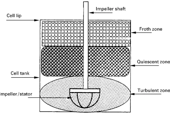
Hydrodynamic Zones
Figure 2 Hydrodynamic zones in a mechanical flotation cell.
Figure 3 Schematic diagram of formation of bubbles in mech-anical cells (after Grainger Allen, 1970; courtesy of Transactions of the Institute of Metallurgy, UK).
bubble}particle aggregates rise up in a relatively less turbulent region. This region also helps in reducing the number of gangue minerals which may have been entrained mechanically or entrapped between bub-bles for upgrading of valuable minerals. The region above the quiescent zone is the froth zone that serves as an additional cleaning step and improves the grade of the concentrate product. The three hydrodynamic zones in mechanical Sotation cells are depicted in Figure 2.
The conSicting functional requirements in dif-ferent zones in a mechanicalSotation cell are a chal-lenge in terms of the cell design and aRne balance of hydrodynamic conditions is necessary for the opti-mum recovery of valuable minerals in a cell.
Gas Dispersion
One of the most important hydrodynamic conditions in a mechanicalSotation cell is dispersion of gas into
Rne bubbles. The bubble generation mechanism in
a mechanical cell is a two-stage process. Firstly, air cavities are formed at the trailing edge of the impeller blades, which is the low pressure region. Thereafter, bubbles form by shedding of vortices from the tail of the cavity, as shown inFigure 3.
The dispersion of air into bubbles can be character-ized by three properties: bubble size, gas hold-up and superRcial gas velocity. Mean bubble size in industrial mechanical cells varies, in general, from 0.5 to 2 mm; gas hold-up varies from 5 to 15% and superRcial gas velocity varies from 0.6 to 1.5 cm s\1, depending on
cell operating conditions (impeller speeds and air rates) and the cell duty in plant operation}roughers, scavenging, cleaners, etc. Recent studies have shown that bubble size, gas hold-up and superRcial gas velo-city cannot describe the gas dispersion in a mechan-ical cell adequately when taken individually; but when taken together the gas dispersion properties determine the bubble surface areaSuxSbin the cell,
which has been shown to characterize gas dispersion very well. Typical Sb values in industrial cells vary
from 30 to 60 s\1. The concept ofS
bhas been found
to be useful in metallurgical scale-up and cell optim-ization, design and selection.
Mode of Air Entry
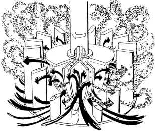
pres-Figure 4 Typical flow patterns in a mechanical flotation cell (courtesy of Outokumpu Mintec Oy, Finland). sure through the hollow shaft to the impeller region.
Self-induced air machines utilize a standpipe which shrouds the drive shaft which is solid. The impeller is located almost in the midpoint of the cell which draws air through the space between the standpipe and the solid shaft.
Flow Patterns
The impeller in a mechanical Sotation cell, during rotation, generates a vortex at the bottom of its blades drawing slurry from its lower section and discharging out from its upper section of the blades. Air is introduced through the impeller shaft or in the spacing between the shaft and a standpipe depending on whether the cell is forced air type or self-induced type, as described above. The dispersed air bubbles come in contact with the slurry close to the impeller discharge point. The aerated slurrySow then leaves the impeller mechanism for the surrounding tank volume. The impeller, therefore, acts as a pump drawing in slurry from below and expelling the aerated slurry to the cell volume. A typicalSow pat-tern of a mechanical cell is shown inFigure 4.
Cell Design
The essential components of a mechanical Sotation cell are described below.
Cell Tank
The proRle of a cell tank is rectangular with truncated corners, U-shaped, conical or cylindrical, depending on cell type and size. Typically, mechanical cells are designed with a rectangular tank bottom for cells with volume up to 3 m3and a U-shaped bottom for
cells with volume up to about 38}45 m3. Cells larger
than 38}45 m3 are typically cylindrical with either
a conical or aSat bottom.Figure 5shows a schematic of different tank designs.
In a typical plant, the mechanical cell tanks are arranged in a series called a bank. The number of cells in a bank varies depending on cell size, application and plant circuit conRguration. The tailings from the
Rrst cell move on as the feed to the second cell and so on and the tailings from the last cell form theRnal tailings of the bank. The concentrates from dif-ferent cells are combined in difdif-ferent ways de-pending on the requirements of the circuit. For example, in a cleaner bank, the concentrates from the
Rrst two cells may be combined to form the Rnal concentrate products, whereas the concentrate prod-uct from the rest of the cells may be combined and recirculated to the feed of the cleaner bank.
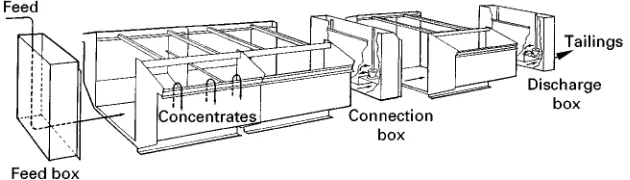
Feed Box and Discharge Box
[image:3.568.130.438.430.692.2]Figure 5 Typical tank designs in mechanical flotation cells.
Figure 6 Schematic of a mechanical cell showing feed box and discharge box and concentrate launders. with a rectangular opening at the bottom of the
box to allow entry of slurry into the cell bank for Sotation. The feed box is rectangular or half-cylindrical in shape depending on cell type and size. A tailings box or discharge box is alsoRtted at the end of the bank (or on the opposite side of feed box in an individual cell) to allow discharge of tailings. The discharge box is also rectangular or half-cylin-drical in shape.Figure 6shows a typical arrangement of a feed and a discharge box in mechanicalSotation cells. For some cell types and sizes, a dart valve or overSow weir areRtted in the discharge box to con-trol pulp level in the cell tank. For other designs, a discharge box is not used and a pinch valve isRtted to the tailings outlet pipeline instead for pulp level control.
Cell Launders
Launders in Sotation cells are located outside the overSow lip to collect and transport the froth or concentrate product out of the cell tank. Launders are typically located on the top of the cell tank, as shown in Figure 1. Launders are designed with a slope of about 10}153 for smooth transportation of froth without blockage in the launders.
The design of launders varies with cell size and type. The launders are located on opposite sides ad-jacent to the feed and discharge boxes in rectangular cell tank designs, as shown in Figure 1. Launders on three sides are also common in rectangular cells
ar-ranged in series. Large cylindrical cells have concen-tric launders which can be either internal or external or both, depending on the capacity of launder neces-sary for froth removal.
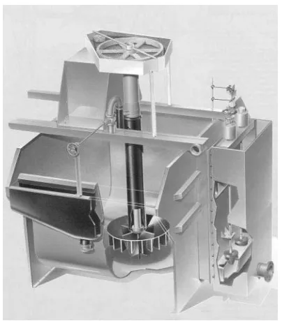
Impellers or Rotors
The impeller or agitator, also referred to as the rotor, is considered to be the heart of a mechanicalSotation cell as it provides the energy to perform the following functions necessary for theSotation process:
1. Suspension of solids in the cell tank. 2. Dispersion of air into bubbles.
3. Creation of microturbulence for effective bub-ble}particle collision.
4. Suction of air into the cell in self-induced type cells.
[image:4.568.128.443.600.690.2]Figure 7 Shapes of different impellers and stators. (A) Bate-man; (B) Dorr-Oliver; (C) Outokumpu; (D) Wemco (courtesy of Bateman Process Equipment, Dorr-Oliver, Outokumpu Mintec Oy and Baker Process, respectively).
submergence varying with cell type and mode of air entry. Figure 7 shows the shapes of different commercially available impellers.
Stators or Diffusers
A stator or diffuser is an important component of a mechanicalSotation cell, which surrounds the impeller and acts as an internal bafSe useful in reducing pulp vortex in the cell. The tangentialSow of the agitated slurry (due to rotation of the impeller) is transformed to a radial direction for effective dispersion of gas and solids in the cell tank. This reduction in the vortex Sow helps in maintaining a stable pulp}froth interface, essential forSotation.
A stator consists of a number of blades arranged in a concentric circle with gaps between the blades to facilitate movement of slurry in the cell tank. A stator is usually mounted on the bottom of the cell tank surrounding the impeller concentrically from its bot-tom. In some cell designs the stator is Rtted to the standpipe such that the stator shrouds the impeller from the top and hangs with an open space at the bottom: this is commonly known as an overhung stator.
The impellers and diffusers are moulded and coated with rubber or polyurethane for abrasion resistance.
Impeller Drive Assembly
The impeller connected to the shaft (hollow or solid) is driven by a three-phase induction motor with the help of V-belts, pulleys or gear box. A typical drive arrangement in a mechanical cell is shown in Fig-ure 1. The size of the drive and the motor pulleys determine the speed at which an impeller operates.
Cell Types and their Designs
Most of the industrial mechanicalSotation cells in the early days (before the 1970s) were of the cell-to-cell type (tanks of different cells connected in a row) for small plants and multistage cleanerSoats where the pumping action of the impellers permitted the transfer of intermediate Sows without external pumps. With the emergence of large Sotation cells, since the early 1980s, dictated by economic consider-ations, open Sow cells (with slurry Sowing openly through a series of cells in a bank) have become prominent.
In the 1980s many mechanical cell designs were prevalent around the world. The major ones are:
1. Agitair cells from Galigher company, USA. 2. Aker machines from Aker Trondelag, Norway. 3. BCS cells from Minemet Industrie, France. 4. Booth cells from Booth Company, USA.
Table 1 Bateman cell tank dimensions for different cell sizes (courtesy of Bateman Process Equipment, South Africa)
Model Volume
(m3)
Height (m)
Depth (m)
Installed motor (kW)
BQR 50 5 2 2 NA
BQR 100 10 2.5 2.5 45
BQR 200 20 3.2 3 55
BQR 300 30 3.6 3.4 75
BQR 400 40 4 3.75 75
BQR 500 55 4.2 4.34 115
BQR 750 75 5.2 4.5 132
[image:6.568.50.277.595.710.2]BQR 1000 100 5.5 4.95 132
Figure 8 A schematic diagram of the Bateman flotation cell (courtesy of Bateman Process Equipment, South Africa). West Germany.
12. Wemco cells, Wemco division, Envirotech, USA.
Only a handful of these cell manufacturers have survived the competitive global market by improving their products or by mergers or by diversiRcation. Manufacturers of Wemco and Outokumpu cells, through research and development, have consistently updated their technology to remain competitive. The recent Tankcells (designated as OK-TC) and Smart-cells from the manufacturers of Outokumpu and Wemco cells, respectively, are an example. Some new designs, such as the Bateman BQ and Svedala RCS cells, have emerged in the mid 1990s. The companies which manufactured Denver and Sala cells have been procured by Svedala and their cells are marketed by Svedala’s Pumps and Process division. The Agitair cells are now marketed by Baker Process (previously known as EIMCO Process Equipment Company). KHD Humboldt Wedag have stopped manufacturing mechanical cells and now market a newly developed pneumatic cell known as PneuSoat.
Presently there are Rve major manufacturers of mechanical Sotation cells. Details of the design fea-tures of different cells are described in the sec-tions below.
Bateman Cell
The BatemanSotation mechanism was developed in 1993 and is presently marketed by the Bateman Pro-cess Equipment Limited. The BQR series of Bateman cells have a round tank design with cell sizes varying
from 5 m3(BQR 50) to 100 m3(BQR 1000). The tank
dimensions of different cells of varying sizes are given inTable 1. The unit cell design Bateman cells are called HiFlo2+and HiClean2+machines.
The Bateman mechanism consists of a hemispher-ical-shaped impeller which is connected to a solid drive shaft. The impeller is designed with no disc on the top and the impeller blades have both the top and bottom opened. The drive shaft is shrouded with a stand pipe. The Bateman mechanism utilizes the forced air entry mode and air is supplied into the mechanism through the gap between the standpipe and the shaft. The mechanism utilizes an overhung-type stator (or diffuser) connected to the bottom of the standpipe, which is a horizontal hood with bafSe plates projecting downwards (Figure 8).
Dorr-Oliver Cells
The Door-Oliver cell is marketed by Dorr-Oliver, a global corporation and member of the Krauss-Maffei Group.
The Dorr-Oliver Company Limited manufacturers
Sotation cells in a wide range of sizes. Cells with a volume of 0.03 m3(DO 1) to 2.8 m3(DO-100) have
aSat-bottom tank design. Cells with volumes from 4.2 to 44 m3 come with a U-shaped tank bottom. Cells
with volumes from 50 to 150 m3 are available with
Table 2 Dorr-Oliver cell tank dimensions for different cell sizes (taken from Dorr-Oliver flotation cell brochure; courtesy of Dorr-Oliver, Australia)
DO conventional cells
Model Volume (m3) Length (m) Width (m) Height (m) Installed motor (kW)
DO 1.0 0.03 0.3 0.3 0.33 0.55
DO 3.5 0.1 0.45 0.45 0.5 0.55
DO 10 0.3 0.65 0.65 0.66 1.1
DO 25 0.7 0.9 0.9 0.86 2.2
DO 50 1.4 1.2 1.2 0.97 4.0
DO 100 2.8 1.52 1.52 1.22 5.5
DO 150 4.2 1.83 1.83 1.53 7.5
DO 300C 8.5 2.29 2.29 1.88 7.5
DO 300 8.5 2.29 2.29 1.88 11.0
DO 500C 14 2.69 2.69 2.46 15
DO 600 17 2.95 2.69 2.46 22
DO 1000 28 3.35 3.35 2.89 30
DO 1350 38 3.81 3.58 3.22 37
DO 1550 44 3.96 3.96 3.22 45
Tank design
Model Volume (m3) Height (m) Diameter (m) Installed motor (kW)
DO 1750 50 3.86 4.32 56
DO 3500 100 5.49 4.65 93
[image:7.568.58.274.432.682.2]DO 5300 150 6.71 4.72 131
Figure 9 Schematic diagram of a large Dorr-Oliver cell (cour-tesy of Dorr-Oliver, Sydney, Australia).
The Door-Oliver mechanism consists of a hemi-spherical-shaped impellerRtted to a hollow shaft. The mechanism utilizes the forced air entry mode in which air is introduced to the impeller through the hollow
shaft. The stators for the Dorr-Oliver cells are gener-ally mounted on the bottom but the large cells mecha-nisms are designed with an overhung stator.
Figure 9 shows a schematic diagram of a large Dorr-Oliver cell with a tank design.
Outokumpu Cells
Outokumpu Mintec, a Finnish company which belongs to the Outokumpu Group, operates inter-nationally and has been the manufacturer of the OutokumpuSotation cell for the last 30 years.
Outokumpu produces different Sotation ma-chines which can be catgorized as:
1. OK conventionalSotation machines: for rougher, scavenger and cleanerSotation.
2. OK-TC (TankCell) Sotation machines: for rougher and scavengerSotation.
3. SK Sotation machines: for Skim-Air Flash S ota-tion in the grinding circuit.
4. HGSotation machines: for cleanerSotation.
The OK conventionalSotation cells are available in volumes up to 38 m3. Conventional cells have a
rectan-gular tank design for cell volumes up to 3 m3; above
3 m3and up to 38 m3the cells have a U-shaped tank.
TankCell designs are available from a volume of 5 m3
Figure 10 A schematic diagram of Outokumpu TankCell (cour-tesy of Outokumpu Mintec Oy, Finland).
Table 3 Outokumpu cell tank dimensions for different cell sizes (taken from Outokumpu flotation cell brochure; courtesy of Outokumpu Mintec Oy, Finland
OK conventional cells
Model Volume (m3) Length (m) Width (m) Height (m) Motor installed (kW)
OK-0.5-R 0.5 NA NA 0.84 2.75}3.75
OK-1.5-R 1.5 NA NA 1.08 5.5}7.5
OK-3-R 3 1.52 1.52 1.21 7.5}11
OK-8-U 8 2.29 2.29 1.88 15}22
OK-16-U 16 2.95 2.69 2.46 30}45
OK-38-U 38 3.49 3.59 3.23 55}75
Model Volume (m3) Height (m) Diameter (m) Motor installed (kW)
Tank Cells
OK-5-TC 5 2.45 2.2 7.5
OK-10-TC 10 2.85 2.7 15
OK-20-TC 20 3.45 3.3 37
OK-30-TC 30 3.9 3.9 45
OK-40-TC 40 4.3 4.1 45
OK-50-TC 50 4.6 4.6 75
OK-70-TC 70 5 5 90
OK-100-TC 100 5.3 5.6 110
OK-130-TC 130 5.4 6.3 132
Extra Hard Duty
OK-100-TC-XHD 100 4.6 6.3 90
OK-130-TC-XHD 130 4.8 6.7 110
OK-160-TC-XHD 160 5.1 7.1 132
cell with aSat bottom (Figure 10). The tank dimen-sions of different cells are given inTable 3.
The OK impeller mechanism is designed with a hemispherical-shaped impeller consisting of a
used in an Outokumpu cell: one is known as the multi-mix or conventional stator and the other is known as free-Sow. The multi-mix stator is typically used forRne particleSotation, whereas the free Sow stator is typically used for coarse particle
Sotation.
Svedala Cells
The former manufacturers of Denver Sotation cells (Denver Equipment, USA) and Sala cells (Sala International in Sweden) have merged together to form the Svedala Pumps and Process Division, which is part of the worldwide Svedala Industri group. Both Denver and Sala cells are available through Svedala companies located worldwide.
[image:8.568.53.518.425.711.2]Table 4 Svedala cell tank dimensions for different cell sizes (taken from Svedala flotation brochure; courtesy of Svedala, UK) Model Volume
(m3)
Height (m)
Diameter (m)
Installed motor (kW)
RCS 5 5 1.9 2 15
RCS 10 10 2.4 2.6 22
RCS 15 15 2.5 3 30
RCS 20 20 3 3.25 37
RCS 30 30 3.4 3.7 45
RCS 40 40 3.8 4.1 55
RCS 50 50 4.1 4.5 75
RCS 70 70 4.6 5 90
RCS 100 100 5.2 5.6 110
RCS 130 130 5.6 6.1 132
RCS 160 160 6.1 6.5 160
[image:9.568.56.515.405.683.2]RCS 200 200 6.5 7 200
Figure 11 A schematic diagram of Svedala RCS cell (courtesy of Svedala, UK).
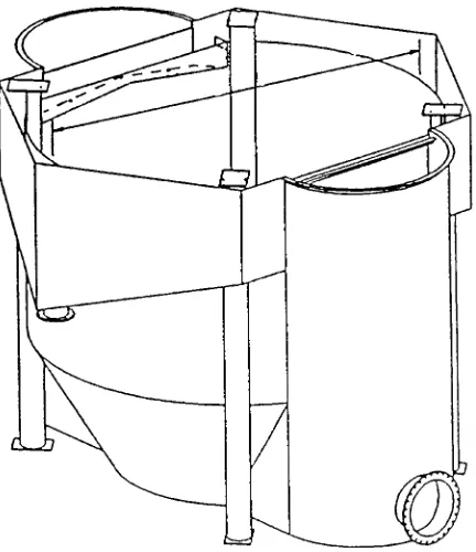
Figure 12 A schematic diagram of Wemco SmartCell (courtesy of Baker Process, USA).
(previously known as Denver cells), in sizes from 0.09 to 42.5 m3; and cell-to cell machines in sizes from
0.08 to 14.2 m3.
In 1995 Svedala developed a new design of S ota-tion cell known as the RCS Flotaota-tion machine which comes in sizes from 5 to 200 m3. The tank dimensions
of different cells sizes are shown inTable 4.
The RCS Flotation machine utilizes a new DV (deep vane) mechanism. The DV mechanism consists of vertical rectangular blades or vanes tapered at the
bottom. The blades are connected to a circular hori-zontal disc located just above the centre of the blades. The mechanism is designed with an overhung stator with vertical vanes projecting downwards connected to the mechanism standpipe. Depending on cell application, the DV mechanism can be modiRed in two different ways to suit the application. The design of the mechanism which allows entry of air through a hollow drive shaft is known as the DVH mechanism (deep vane and hollow shaft), whereas the design which allows entry of air through a concentric stand-pipe is known as the DVS mechanism (deep vane and solid shaft).
Figure 11 shows a schematic of the Svedala RCS
Sotation cell, showing the DV mechanism and the cell tank design.
Wemco Cells
Wemco Sotation cells are manufactured by Baker Process, which also makes Agitair cells and pyramid column cells.
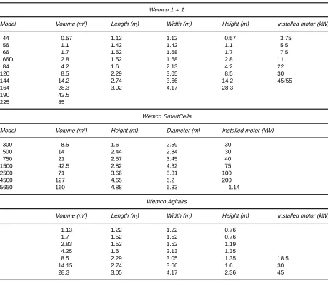
There are two major Wemco designs, the Wemco 1#1 design and new SmartCell design (Figure 12). The 1#1 design comes in cell sizes from 0.57 to 85 m3. The SmartCell design comes in sizes from 8.5
to 160 m3. The Wemco 1#1 cell utilizes the
66D 2.8 1.52 1.68 2.8 11
84 4.2 1.6 2.13 4.2 22
120 8.5 2.29 3.05 8.5 30
144 14.2 2.74 3.66 14.2 45/55
164 28.3 3.02 4.17 28.3
190 42.5
225 85
Wemco SmartCells
Model Volume (m3) Height (m) Diameter (m) Installed motor (kW)
300 8.5 1.6 2.59 30
500 14 2.44 2.84 30
750 21 2.57 3.45 40
1500 42.5 2.82 4.32 75
2500 71 3.66 5.31 100
4500 127 4.65 6.2 200
5650 160 4.88 6.83 1.14
Wemco Agitairs
Volume (m3) Length (m) Width (m) Height (m) Installed motor (kW)
1.13 1.22 1.22 0.76
1.7 1.52 1.52 0.76
2.83 1.52 1.52 1.19
4.25 1.6 2.13 1.35
8.5 2.29 3.05 1.35 18.5
14.15 2.74 3.66 1.6 30
28.3 3.05 4.17 2.36 45
[image:10.568.51.510.78.472.2]disperser, standpipe and a hood. The larger cells are designed with a false bottom and draught tube. The SmartCell Sotation machine utilizes the Wemco 1#1 aeration mechanism which is reconRgured and embedded with an expert control system. The dimen-sions of different Wemco cells are shown in Table 5.
The air and pulp circulation in the Wemco cells are determined by the rotor size, speed and submergence in the pulp. Liquid circulation and air transfer are a function of rotor speed, size and sub-mergence.
Present and Future Trends
Traditionally, Sotation machine design closely fol-lows the trend of comminution machines in mineral-processing plants. Due to economic considerations in
the processing of low grade ores, the present com-minution machines such as crushers, semi-autogous, autogenous and ball mills are designed for very high capacities. The Cadia Hill Mine in New South Wales, Australia, which treats a copper-gold ore at the rate of 2100 tonnes per hour, utilizes a 12 m diameter SAG mill (with a 20 MW motor) and two 6.5;11 m ball mills (each with a 8.75 MW motor). To be com-patible with the comminution circuit, large capacity 150 m3Sotation cells are used in the rougher circuit.
At present, cells are large as 300 m3 are being
designed by various manufacturers. Installation of large cells has many advantages:
5. easy control;
6. reduced reagent consumption.
However, with increase in cell size, the problem of machine design and metallurgical scale-up becomes more acute. The scale-up features that may have been tolerated on smaller cells are not applicable to larger cells. The simple similitude considerations used in terms of dimensionless numbers (power number, Froude number, airSow number, Reynolds number) are not sufRcient to design large machines. The development and evaluation costs rapidly increase with cell size, which calls for a more rational and fundamental basis in cell design. Extensive research at the Julius Kruttschnitt Mineral Research Centre in Brisbane has shown that bubble surface areaSux or Sbis an important criterion for metallurgical scale-up,
which will gain more prominence in the future and will be considered as a parameter in conjunction with other important dimensionless numbers used in ma-chine design and scale-up.
An increase in cell sizes also requires more ef-fective froth transportation due to the increase in travel time of bubble}particle aggregates which re-sults in high drop-back and low froth recovery. To address the problem of froth transportation and stab-ility in large cells, new design features such as internal launders, double launders, high capacity launders, booster cones, froth crowders, cross-launders and beehive launders are emerging. More work will be carried out by cell manufacturers and researchers to understand froth transportation and froth recovery. The effect of the interactions of different launder designs, froth crowders and cell-operating parameters such as impeller speed, air rate and froth depth will be the subject of further investigation for better cell design and optimization of cell operation.
The design differences of various cells mar-keted by different manufacturers are in fact dif-ferences in impeller/stator mechanisms and air input systems (either self-induced or forced air type through a standpipe with a solid shaft or through a hollow shaft). However, the design of tanks is similar for different cell types, and resembles the cylindrical design of the old Maxwell cells. The launder and froth crowding devices in different designs are tailor-made to suit different applications.
The large new Sotation cells are equipped with integrated control systems. The recent trend of instal-lation of a few large cells in a circuit will see more control instrumentation like airSow control, variable speed drive for speed control, as well as online
measurement equipment for monitoring bubble size, superRcial gas velocity, gas hold-up and bubble sur-face area Sux, which will be used for better cell performance optimization. Froth vision equipment will also gain prominence for better control of froth in the largeSotation cells.
The development of Sotation cells will continue as more and more Rne particle processing will be necessary in future. The large Sotation machines will have to be designed to generate very small bubbles and a high degree of microturbulence for effective bubble}particle collision to remain competitive against other novel technologies like high intensity pneumatic cells. Entrainment will be a ma-jor issue in concentrators, which will need reRnement of froth-washing technologies in mechanicalSotation cells.
Acknowledgements
The authors would like to thank the manufacturers of Bateman, Dorr-Oliver, Outokumpu, Svedala and Wemco cells for providing sale catalogues, pictures and other information regarding their Sotation cells.
Further Reading
Bezuidenhout G (1995) The BatemanSotation machine. XIX International Mineral Processing Congress 3: 231}236.
Degner VR (1988) Flotation machine design. In: Klimpel RR and Luckie PT (eds)Proceedings of Industrial Prac-tice of Fine Coal Processing, SME/AIME, ch. 16, pp. 135}146. Somerset, CA.
Grainger Allen TJN (1970) Bubble generation in froth Sotation machines.Transactions of the Institute of Min-ing and Metallurgy79: C15}C22.
Harris CC (1986) Flotation machine design, scale-up and performance: database. In: Advances in Mineral Pro-ceedings, ch. 37, pp. 618}638. SME/AIME.
Nitti T and Tarvainen M (1982) Experiences with large OutokumpuSotation machines. In:XIV International Mineral Processing Congress, pp. VI 7.1}7.12. Toronto, Canada.
Schubert H (1985) On some aspects of the hydrodynamics ofSotation process. In: Forssberg KSE (ed.)Flotation of Sulphide Minerals, pp. 337}355. Amsterdam: Elsevier.
Smith EL, Prevett MJ and Lawrence GA (1982) An improved mechanism for large Sotation cells. In: XV International Mineral Processing Congress, pp. VI 9.1}9.19.