© 2019, IRJET | Impact Factor value: 7.211 | ISO 9001:2008 Certified Journal
| Page 2994
Design Optimization of Snap Fit Feature of Lock Plate to Reduce its
Installation Force by using DOE Methodology
Hrishikesh S Kakade
1, Vinod G Patil
21
Student, Dr. D Y Patil School of Engineering, Lohegaon, India.
2
Assi. Professor Dr. D Y Patil School of Engineering, Lohegaon, India.
---***---Abstract - Snap fit joints are widely used in industry for assembling different parts. Snap fits are simplest, quickest and most effective joints unless they are designed with requisite dimensions and parameters. In the present study many parameters are studied and investigated which are affecting the assembly process of snap fit joints. For this purpose we have used the design of experiments (DoE) method, which has provided us the statistical approach and lead us to a reliable and significant interpretation of different parameters of snap fit joint those are responsible for high installation force while assembly process. The design modifications of snap fit joint has been carried out by identifying and establishing relation between the parameters. The modified design of snap fit joint has ensured the installation force of assembly process is within the human ergonomic limit.
Key Words: Snap Fit, Design of experiments, Snap in force, Lock plate, Plastics, Polypropylene.
1. INTRODUCTION
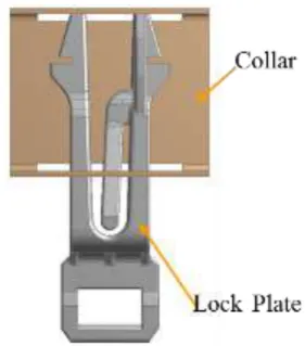
THIS document presents the study carried out on geometrical parameters of snap fit joint of lock plate that are affecting the installation force of assembly. Lock plate is one of the most important parts of door assembly in dish-washer. Function of the lock plate is to lock the door on its place and do not allow to open once get locked. Snap fit feature has been provided on the lock plate which will makes the assembly process of lock plate fast, easy and cost effective. But on actual assembly line it was observed that installation force required to assemble the lock plate is more than human ergonomic limit and making the assembly process difficult.
This is the functional failure of the snap fit feature of lock plate. Design of snap fit feature is modified which will ensures the easy engagement of lock plate with the collar and make the assembly process fast, easy & reliable. Design of snap fit feature is most important task which makes the assembly and disassembly process feasible & effortless. There are different geometric parameters of snap fit joint which separately or in combination affect the snap in force of assembly.
Cantilever hook type snap feature is commonly used in snap fit joints. Strength, constraint, compatibility, and robustness have been identified as the key requirements of snap-fit design. Robustness refers to the tolerance of
[image:1.595.366.507.407.567.2]dimensional variation. It is unpredictable because dimensions vary according to fabrication and assembly conditions. The most critical dimension variation is the interference between snap-fit hook and mating part. Although very small, the amount of interference determines the insertion force and hence the quality of the snap-fit. Since snap-fit connectors behave like cantilevers, the insertion force increases with increasing interference. Too little interference and the associated insertion force would cause loose assembly. Too much interference and the associated mating force would cause difficult assembly or possibly permanent deformation of parts and connectors. The failure of parts is more costly. Like many contact-aided mechanisms, a successful design of snap-fit connectors requires accurate calculation of interference-induced insertion force.
Fig. 1: Lock plate with snap fit feature
2. METHODOLOGY
© 2019, IRJET | Impact Factor value: 7.211 | ISO 9001:2008 Certified Journal
| Page 2995
It is very important to find out the cause of high installation force, hence it is decided to consider multiple factors at a time which may affect the installation force. Considering only one factor at a time is unscientific way to solve the problem. For this purpose we have used the design of experiments (DoE) method, which has provided us the statistical approach and led us towards the more optimized model. Physical study of the lock plate is carried out and geometrical parameters which are affecting the installation force of lock plate are identified.
This DoE has determined the significance of each geometric parameter and relationship between these parameters & installation force. The statistical analysis from the DoE lead us to a reliable and significant interpretation of different parameters of snap fit joint those are responsible for high installation force while assembly process. The design modifications of snap fit joint has been carried out accordingly.
The confirmation test of the final modified design of snap fit feature of lock plate is carried out and it is ensured that the installation force is within the human ergonomic limit.
3. PROBLEM STATEMENT:
Snap fit feature has been provided on lock plate to make the connection with collar and to make the assembly process easy, cost effective & fast. But It is observed that high installation force is required on assembly line while installing lock plate.
This has made the installation more time consuming and uncomfotable. Hence it is the functional failure of the snap fit feature of lock plate. Current design of snap fit feature of lock plate need to modify & optimize so that installation force will be within the ergonomic limit of 44N and the assembly process will be less time consuming, effective & comfortable.
4. Mathematical model:
The type of the snap fit in lock plate in cantilever type.It is suggested to design the finger so that either its thickness (h) or width (b) tapers from the root to the hook; in this way the load-bearing cross section at any point bears a more appropriate relation to the local load. The maximum strain on the material can therefore be reduced, and less material is needed.
Fig.2: Cantilever snap fit
If the snap fit has to be insert without any permanent deflection (plastic deformation), the retention or pull-off force must be below a maximum value, the elastic strain limit, but high enough to retain engagement under normal service load. The insertion or assembly force is defined as,
And
Where,
W=Assembly or insertion force
P=Perpendicular force
u=coefficient of friction
α=lead angle
b=beam width
t=Beam thickness
L=Beam length
E=Flexural modulus
e=Strain at base
Table.1 : Calculation for snap in force
Sr no Parameter Value unit
1 beam width 4.5212 mm
2 beam thickness 4.699 mm
3 beam length 54.991 mm
4 deflection 2.159 mm
5 lead angle 18.65 degree
6 coefficient of friction 0.4 --
7 flexural modulus 9000 Mpa
8 Deflection magnifying factor 3
--
9 Perpendicular force 19 N
output Snap in force 42 N
5. Finite element analysis
© 2019, IRJET | Impact Factor value: 7.211 | ISO 9001:2008 Certified Journal
| Page 2996
out.Multi-linear stress strain curve, frictional contact between mating arts and geometric non linearity has been defined in FE model. Non linear analysis is carried by using ANSYS software package.
Firstly, finite element analysis has been carried out on current design (baseline model). The fine mesh is used so as to get the most accurate results.
5.1 Material Properties
[image:3.595.327.548.208.374.2]All materials are assumed to be homogeneous and isotropic. Polypropylene 30% Glass filled (PP30%GF) material has been used for lock plate and steel material has been used for collar. Density, young’s modulus and poisons ratio are defined. Table 1. Shows the material properties of PP30%GF. Material of lock plate is plastic (PP30%GF) so to ensure the realistic resuts from FEA, multi-linear isoropic properties has been defined for PP30%GF. As collar is not area of interest to reduce solver time, inear proprties has been defined for steel material. Table 2. Shows the material properties of the steel and PP30%GF.
Table 2. Material properties
Part Material Young’s Modulus (MPa)
Tensile Strength (MPa)
Strain at break
%
Lock
Plate PP 30%GF 10500 140 2.5
Collar Steel 210000 250 0.45
5.2Loads and Boundary conditions
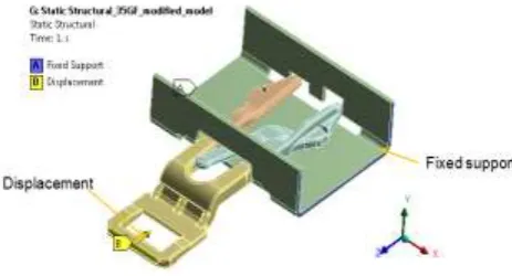
Collar is fixed at its edges in all DOF. Displacement in axial direction is applied at the end of lock plate so that it will get inserted into the collar.The reaction force is measured at the displacement location which is the required snap in force.Following figure shows the loading and boundary conditions for lock plate.
Fig. 3 Loads and Boundary conditions
5.3 Analysis results of Baseline model
Following graph shows the snap in force observed for baseline model.The snap in force is gradually increaing to a peak value and then it suddenly drops down, the peak point of the graph is the ponit when lock plate is completely inerted and gets installed into collar.The snap in force observed is 52.1N which is exceeding the allowable ergonomic limit of 44N.
Fig. 4 Graph for Snap in Force baseline model
[image:3.595.326.572.462.653.2]Following figures shows the maximun principle stress plot and max principle strain plot. The max. principle stress occured on lock plate is 97.7 MPa which is less than yeild strength of 140MPa.
Fig.5: Max principle stress plot- baseline model
[image:3.595.39.271.611.736.2]© 2019, IRJET | Impact Factor value: 7.211 | ISO 9001:2008 Certified Journal
| Page 2997
Fig. 4 Max principle strain plot- baseline model
6. Design of experiment (DoE)
Design of experiment is considered one of the most comprehensive approach in product development.It is the statistical approach that attempts to provide predictive knowledge of complex, multi variable process with few trails.
[image:4.595.43.287.446.572.2]Full factorail design approach method is used in this study which consist of more than two factors at a time.Two leves are set for each variable.In the first step the variables i.e geometric parameters affecting installaation force are found out by physical study of lock plate.Following are the factor consdered in DoE study.
Fig. 5 Geometric parameters i.e Factors
According to orthogonal experimental design, a two-level full factorial DOE with four factors needs 24 (equal to
16) experimental runs.
There are total 16 runs to be carried out. The different 16 CAD models have been prepared according to the level setting of geometric parameters.Non linear ANSYS software has been used to conduct thses 16 runs.The value of the snap in force has been noted down.Following table indicates the level setting and output value for the 16 runs.
Table 3. DOE run (Orthogonal array) with output (snap in force)
Run (mm) X1 (deg) X2 (mm) X3 (mm) X4 Snap In Force (N)
1 16.8 5 0.2 7.5 11.2
2 16.8 5 0.2 9 7.2
3 16.8 5 4 7.5 2.33
4 16.8 5 4 9 11.72
5 16.8 15.6 0.2 7.5 20.5
6 16.8 15.6 0.2 9 45.54
7 16.8 15.6 4 7.5 40.677
8 16.8 15.6 4 9 25.38
9 17.8 5 0.2 7.5 3.4
10 17.8 5 0.2 9 12.09
11 17.8 5 4 7.5 4.69
12 17.8 5 4 9 7.33
13 17.8 15.6 0.2 7.5 52.8
14 17.8 15.6 0.2 9 33.2
15 17.8 15.6 4 7.5 29.68
16 17.8 15.6 4 9 55.13
7. Results analysis
Finite element method was used to produce the sample data for the response of the cantilever hook integral attachment featureFor the investigated range of factor dimensions, these design equations provide a closer approximation than the analytical equations to the finite element results. These results also appear to be linearly dependent on the material properties, which can be easily incorporated into the design equations.
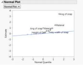
[image:4.595.351.524.606.742.2]Followig figure 6 shows NPP plots, which shows that Ang of snap, entry width, there interactions, Entry width of snap*Ang of snap and Entry width of snap*Height of arm as significance.
© 2019, IRJET | Impact Factor value: 7.211 | ISO 9001:2008 Certified Journal
| Page 2998
Following figure 7 shows pareto plot. Pareto Plots clearly shows that Ang of snap, is significance with higher estimate followed by entry width of snap and there interactions.
Fig.7: Pareto plot
The main effect plot is indicated in figure 8.It is observed from main effect plot that with increase in angle of snap the snap in force increases, so optimum force can be obtained for positive side of level setting i.e 15.6degree.
With increase in entry width of snap, the snap in force increases, so optimun value is observed from the main effect graph is for positive side level setting.
With increase in roundness value of snap the snap in force value decreases, hence the optimun value of snap in force is observed for positive side of level setting.
The snap in force value decreased first with increase in height of arm, then it is increased, so optimum value will be observed at negative side level setting of deflector arm.
Fig.8: Main effect plot
Following figure 9 indicates the percentage of variation in snap in force explained by this analysis. 95% variation is successfully achieved with the current variation study.
Fig.9: R-sq Plot
8. Optimized model
Statistical approach of Design of experiment method has given us the relationship between geometric parameters and snap in force of lock plate.From the DOE study it is observed that angle of the snap, entry width followed by roundeness at the corner and their interaction is significant with higher estimates. Accordingly the design of lock plate is modified.Following figure 10. Shows the optimised model.
Fig10:Optimised model
FE analyss has been carried out on optimised model to find out the snap in force.From the FE analysis it is observed that snap in force for optimised model is 40.68 N which is below allowable ergonomic limit of 44N.
© 2019, IRJET | Impact Factor value: 7.211 | ISO 9001:2008 Certified Journal
| Page 2999
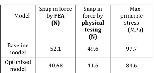
Table 5. Result summary
Model Snap in force by FEA (N)
Snap in force by physical
tesing (N)
Max. principle
stress (MPa)
Baseline
model 52.1 49.6 97.7
Optimized
model 40.68 41.6 84.6
The snap in force for he lock plate model is reduced in optimised model within ergonomic limit also max principle stress in optimised model is well below the yeild strength of material.
Physical testing results of baseline model it is observed that there is only 4% difference with FEA results. For the optimised model confirmation testing is to be carried out.
9. CONCLUSIONS
The present work has successfully demonstrated the application of Design of experiment methodology for multi variable optimization of design parameters in snap fit feature of lock plate.
The snap in force was measured for the multi variable geometric parameters. The final conclusions arrived, at the end of this work are as follows:
• The main parameter affecting the snap in force was agnle of snap, entry width followed by roundness at the edge of the snap.
• Self aligning profile provided on optimized model eliminated the chances of mis-alignment while installation.
• Design of lock plate is successfully optimized so that installation force is within the human ergonomic limit of 44 N, DOE method has provided the engineering and statistical path for solving the multi-variable problem.
REFERENCES
[1] Emiloi A Ramirez et. al. “Methodology for design process of snap fit joint by additive Manufacturing” 12th CIRP Conference on Intelligent Computation in Manufacturing Engineering, 18-20 July 2018, Gulf of Naples, Italy
[2] Ikechukwu Onyegiri, et al, “Threaded connectors for sandwich pipes – Part 2: Optimisation of stress relief groove,” International Journal of Pressure Vessels and Piping 168 [2018] 125-131.
[3] Zhu Yuefeng et al, “Design of active disassembly snap-fit based on electrothermal stimulation method,” BTAIJ, 10(16), 2014 [9308-9312] 2014 volume10 issue 16.
[4] Jingjing Ji Kok-Meng et al, “Cantilever Snap-Fit Performance Analysis for Haptic Evaluation” ASME 121004-8 / Vol. 133, December 2011.
[5] Samruddhi Rao et.al., “An Overview of Taguchi Method: Evolution, Concept and Interdisciplinary Applications” International Journal of Scientific & Engineering Research, Volume 4, Issue 10, October-2013
[6] Srinivas Athreya et.al “Application Of Taguchi Method For Optimization Of Process Parameters In Improving The Surface Roughness Of Lathe Facing Operation”, International Refereed Journal of Engineering and Science (IRJES) Volume 1, Issue 3 (November 2012), PP.13-19
[7] Li Yongfana et.al., “Research on the Optimization Design of Motorcycle Engine Based on DOE Methodology ” Sci-direct, 13th Global Congress on Manufacturing and Management, GCMM 2016
[8] Christoph Klahn et.al, “Design Guidelines for Additive Manufactured Snap-Fit Joints 26th CIRP Design Conference, Procedia CIRP 50 ( 2016 ) 264 – 269.
[9] L Goteti et.al, “design optimization of snap-fit integral parts by fea and statistical Analysis”, ASME International Mechanical Engineering Congress and Exposition November 5-10, 2006, Chicago, Illinois, USA.
BIOGRAPHIES
Hrishikesh Sudhakar kakade Student of Masters in Design engineering, Dept. of mechanical, Dr. D Y Patil School of engineering, Lohegaon, Pune.