•
-\ ": "' .. •· ~· ·. . ..
..
·:' •::·:~·'):
~~
0~L-~i~-~~~~~~-~---T·M·9·2·s·4-94~
., .. '·
"])fl,~
MICROMEMORY 7405
ADD-ON MEMORY SYSTEM
11
lnformation contained in this Technical Manual is disclosed in confidence and may not be dupli-cated in full or in part by any person without prior written approval ot~the Memory Products Division. Its sole purpose is to provide the user with adequately detailed documentation so as to efficiently install, operate. maintain, and order spare parts for the equipment supplied. The use of this document tor all other purposes is specif· featly prohibited." ..
ELECTRONIC MEMORIES & MAGNETICS CORPORATION
12621 Chadron Avenue. Hawthorne. California 90250 I Telephone: {213) 644-9881
~ ~~~---~---
·-_· ---· -_-
~;;x;
·
1~~n·~,;;-~DD Pl\Gl~
•.-I~,._~
• Par00rc1ph No. ( r::v0r. Paqe) Puhl .i c;·, t ion
:~o. ~aqrn
ph No. (OddP.•J<;:~)
•9. ic
I
(
1 . )1
J
< . )I ... .
i -112}-._,•, .. t_ .... ll.
c
''l"\ l c r. l. I1 c·.... Oc·1 r}c··
c 11 ~-.r".\ l~ 1 J l"' ("\ce
I
I " .__. - ··- '- · · ---'--"·'_·_-_,_---_ _ _ _ _ _ _, 1. · t; 1
pacc!.:;
.1 li':i.rst I.in0 ,, ( "' ., ... ~.-.
nr
'I\·ihle rritlt:?
-> 4 5
6
7 8
9
10 11 12 13
14
i~
I
17 18: 19; I 20: 21
I
22: 23
j·
24 I
2,.. ::i I
I
2r
2.,..,.,,
28
29
30
I
31
~;
1---34 35 36 37 38
391
40
41
42 43f
44
45
46 47
r
I
I
I
I
I
II
I
I
I
I
I
I I
I
I
I
. --
·-/\~=-==-==--..:.-=--:=--=~~-;_ ~:F 0 REWORD ·-....
---==--~--~~-=!.-;:=·~=-.:..J.
"'.f
I
! - -. . . --~·I
"'===---,= ... --
s~~·;':~~=~;·itlc
--
:
I
:
This manual contains
informatic~~_
r~q~iredto install
1I
operate, and maintain the MICROMEMORY
74~5Add-on
Memory System
1part number 929494
1manufactured by
Electronic Memories and Magnetics Corporation,
Hawthorne, California.
i
l
This 7405 Memory System is self-contained
1with memory
I
I
I
I
I
I
I i
!-:-:~:-:--·
' '
power supply and interface electronics_ for complete
...
~pmpatibilitywith PDP-:11 Computer Systems. manufactured. _____
.
---J
I
by Digital Equipment Corporation,
~aynard,Massachusetts.
I
Landscape Illustra~ion
Height
for Full Page
Vertical Illustration
or
Width
for Full Pilge
Landscupe Illustrati6n
,.
48 .... "\·
49 . "'
so
L_ - ____
v
____ - - -
----...:.---1..J
5·
srr_···
---~---53 . L ... ,,·:t J,in0 of rl.'c~·~t
---1---~
F!vc~n Paqe» No. Center P:'lqc No. Odd PuqC No.
2
3
4
5
6
7
8
9
10 11 12 13
14
15
16
17
18
19 20
21
22
23
24
25
26
27 28
29
30
31
32
33
34
35
'"'·-,,.~ ~
..
-l··<j:---
TEXrr WID'I1Il ODD P.AGE·---*"-:;:
Paraqrz1µh No. (Ever:, P:.1qc!) Public;1tior1 No. P<:i.r;J~p~wph No. (Odd P0qc..)'rEX'r HID'I.'Il EVr~N' Pl\G r~
<.-:.G.'---~~~le
, _ _ _.... _ _ _ _ _ _ (r:vcn Ct'"'nlcrlinc) ( .L~ld~~1
Centerline)'----.S~~~~~
~
I
J.o' i :c d: Lin C! n f rr c:~
t () r 'J.' i.1 b l cr1~
i. t l cI
2 1
-r::::::.--=-=--=-::::.-=-=::.:;
·~...;..-= ..
=--=.-:-::::-:::::.-:::;.--;-:;-.;.-~..::~~slicr ic)N'~ ;.i...:.:.-::::;:;-.;.=::-:-.::.""=-::.-::.-=-:--=-=-:=-=-=-·=-..:=·~-=-·-1 ·
-·1
3
I
I
! ·' . -·~_:..:...; - ·-- _.;..._:.:.._: __ •I
i
!
r===r===--=--~~"ffE~~~( pEi;~Ri~:-rlO-N
-
- = - - -
17
I
I
I
.
.
8 I i ·
9
I
1-1.GENERAL
10
I ·
l
11
I
1-~·The MICROMEMORY
7405Memory System consists of an Electronic Memories
12
I standard. chassis containing one to four
32Kx
16*MICROMEMORY 3000QD ·cards,
13
I
141
l
a~ower
Supply and a special UNIBUS-adaptable Interface Card.
Switches on
f~
I.
fthe Interface Card can be set to designate the Memory System for operation
17 f
~within
an address block recognizable by the Computer.
18
I
!
! ·, ;· ic1 ~:.: l ~~:.: l'.' ;?·;_:;.l. 1_ ? -?1 c219 ; ! 1-3.
The Memory System is modularly organized in
32Ksub-blocks with each
I • .. ·~. . . . . ., . . . . . . ·~ .!..., • . . . . r
2 0
I
I
Memory Card constituting one._ sub-block. · Thus, the System can be populated
2" I I . .
2
~
j
i
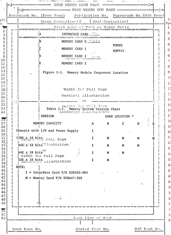
iii.COrrespOilciiiiii
illCTenifl~tS·:--·Tiibie
1..:1ii1dicates system VeTsiOi15 based On
;~
! :
nuniber of Memory Cards and,
-~,~;i~~c:~~~~j~;;;~ f~~i~e
1-1illustrates Card
Ii1
and Power Supply locations.
• .i
I
IY6
j
I - ~27 t
I
1-4.POWER
SUPPLY ·1?8
I
I2
9I
I
1-?.The Power Supply is capable of supplying all necessary de operating
30
I
1 1vo~tages
for a full-populated Memory Module.
The Power Supply also provides.
31
I 115
·vac t'o the cooling fans located within the Memory Module.
For detailed
32
33
I
de~c-ription
of Power Suppi'y see Technical Manual TM929219.
34
I
I .35 36
37
38 39 40
41
42
43
44
45 46 47
48
~9
~1
52
I 1-6.
MEMORY CARDS
I
I \·!id th for l~111
PageI
I 1-7 . ..,
-~Each.Memory Card
.i.~.a .complete
32K x16
(or
18)memory subsystem on 'a
I I .J.J ~ l.;. - - · ··"·-- •• .;; • - ... - • ..• • - ... 1. • .1. ._ . . .
I
single printed wiring board, including semiconductor memory array and support.
·:
el~ctronics.
'Refer to Technical Manual
TM929162for description of the Memory
1
card. -
I
I
I -
I
I 1-S.
INTERFACE CARD
I
I
I
.
I
1-9. The Interface Card is a buffer/controller unit installed between the
I I i
I
I
PDP-11 UNIBUS and
th~ M~moryCards that constitute the Memory System.
: I .
'I:
.
.
IL::~;n::e~~~b~~ ~o:~ w~en
parity
C:Pt:~:-~nc~u:~---
- - - -
--r.J
53 r..1~~ t T.i nt'." n f ·r.cxt
---,
Even P"lCJC No. Center P~HJC No.
1
2
3
4
5
6 7.
9
JO
11 ] ' )
.I!.
} 5
..
,...l..0
17 18 19
22 ?':'
._ _,
24
I 2S
j
' . :? Ci
28 29
30
31
32
~~9r~1pl._1_N_o_._( ... E_'..,_1c_!r_~_Paqc) Pn})J.ico tion No. Par.agraph No. (Ocld Paqe)
"
['~. ~.::J---T_._E_x_~r_N_r_n~:~x~v:.;~D;~G~DD
Pl\GE -· __________
:_?~-t
; !
c- l
(
r:v encc
nLe~
r 1 inc )1._ ___
L~~-l
c_1_c_ ...
_c_n_t_. c_r_-1_1_· r_1_e_) _ _ _ _ _ _ _ - + - - - , 8~= ~~;
J -.
1J10. CAPACITY ·.~' i.1·:.;t Linc of 'J'<~'~t: ot- 'I'~1ble Ti.tJ e2. r-
-r.:.;:.::-.::.-=·
;~·~ :::.:.-.·..:·=-· :~-::.:.= -.:.-:::-:.::.-:-.::..:-:: ;.-::::::-::.-:;-·.;:.-:~-:,~-=--;.;-~:.~ .;.~.~-..::-~-:::::;· ~.--. .-;.-:-_-:::.:-:.-:::.:-:::;;.:-;..~--~..:.:=-= -:::-:.=:..-=---=--::::-;::;-;::::--t
I
3
I
1--11. The Interface Card can pTovidc buffering and control for up to 124K :4
I
1 "· ·:·; .. -.:~~..:.::::-:. ·:.-::;::~-~; :.. =.:..~·,: . . - · ;~. ~· _.:.:.: ·~.:=...:..-~:-~.-... .c..·.: • .-:.-: ~ ... ; .... ··• · -.. - ·;-. • •. •. _:-;; .. ·.·.- . ·-:--... ;.;.-. ~-=· -:;~--=:.;--..;,-:.:::.::-:: :-::-.. ::;;:::.~=::~·~-=;.:::-.:=-~.:;.;.;.:-::;. •5
I
ltbit words ;(including two p:_rity_ ~its)__:>~~~~-48K 9-bit bytes, depending on1
6 i
I
o~erating mode.z
I
l
1~12.
MODES OF OPERATION
9
I
i
Dr0'": D:"'n: ... r;i,'"'·:t10 1-1.3. The Interface Card can accommodate the Memory System for operation 11
12 13
I
14 i i:::I
is!
\17
!
18!
19I
20 l
~;I;
23
/1!
l
I
-.-1
26
j
271
2P
29
30
I
3i
32·f
33 3.J. 35 36 37 38 39 40
4'1
42 43
44
45
46
47
48
,
~)I
iri the following modes:
f
I
ti
ACCESS TIME
Read/Restore Word,
Clear/Write Word,
Exchange Word (Read/Modify/Write)
Read/Rest9re Either Byte.,
.,
.Cl ear/Write Other Bytes·'-'-""-"-• :.
--
... :.. _ ... _ ,,. ' . ··~ \.'. ...V~=tical IlJustration
!-.. 1-.15.--·-Access and cycle times are as follows:
--·----·-¥
l .
iI
.. f
. I
i
l-'16. SYSTEM OPTION
t
Access Time
Acc.ess· 'Time with parity - ·':ion
Cycle Time
!
I
i
I
I
1-17. The Memory System can optionally include pTovisions for checking and
sto:r.:_~.~~- t~? pal:'i ty _bi ts_ ... W~en this option is included, each MemoTy Card must
. J _,
include two extTa bit storage capacity.
i ... - - .. -· ·- . .. . .
.
Card capacity must be 32K x 18~t
1-18. SYSTEM SPECIFICATIONS
I
i
t ·!id th~~
r: .1:." F L1 , 'l ·;) ;~
('f e . . .l
1-J9. A sununary of -Memory System spec1f1cat1onst
!
is contained in Table 1-2.
f ~ J. • ;-~) ,,."\ ;~ ~ 1 .. -. -~--r·· , '. .. , . I 1 • ~ , : :_-l- -: .'. -~ • ~~ ~) r,
Fo·r details of Memory Card specifications, see Technical Manual TM92864 7. ·
I
l
l
I I
I
l
I
I I
I
...
'
I ' • ..
L_ - _. __
_jj_ ___ - - - · - - - ...
~_l
L.---'
Even Pi.lqe No. Oc1c1 Pi.1CJC ~!n.
1
2 3
4
5
6
7
8
9
10
11
J.2
] ... -::
14
15
16
17
18
19
21
... ,,
..
.
' ,_-27
2fl
29
30
3]
32
~
..
~i . ~
'l1
E!X.'.I' WID'fII EVEN Pl\G T::
:·1:1
. !«::•?---
'l'EX'r WID'11II ODD PAGE!
---t-t·
P;:1rciq r~1 ph No. (Ever. Pz.19c) Pub 1 ica t ion No. Parn~p:-aph No. (Odd P(l<lC')
· · : 1
-1-1/
1glcLCC _ _ _ , _ _
(_I:_·;v~c-·.1_1_~(!1:tc1:-lit\(')_
!. _ _ j_(Odti. Centerline)I
I
P·i '~et· J.: "'"\:""' {'~7 r}'f'"'"-•·1• l') •• nlc.,}·)l,... Tl.0J-] C
I
~$pilCC 2 3 4 5 6 7 8 9 10 11 12
13
lLL .
l~ l
l~
I .
17 !
·1s
I
19 !20
I
2 ,I
2~
I
23,
241
~1
27 i
281
29 30. 31 32_ -·
331
34 35 36 37 38 39 4041
42 4344
45 46 47 48 49~
52- - .l '··' ~ .t .a. • .. . L ... ~ . L. J. .J. "-' \ ; • l_ •.
r
--c·
--·
i"- -- -·- _.;.-·:;-::-"';~;:·::;.:::-;;:.;.-:::.=--:;:.:.:;-;,.:;:;.-.:.-:..-:::::..;-.::::-.. :.:.:::-~-.-:::..~-==--=-:...-:--;;.;- .. • - . ···- ·'---,I
-~=-=--==:}~~~~-=::=·~.-~~~~!:!:~~~~-~!
..
-;.~~~-~:~~=~---~---·-·---==-J
I
lB
MEMORY CARD 0.··~_tJJ!
I
l
POWERI
.c
MEMORY. CARD 1I
ID
MEMORY CARD 2 ;;·:· ·;·'.'.: SUPPLYI
!
M_ .. __ . ·----· ..
-·~-·-···--·-I
IE
MEMORY CARD 3 tI
I
I
I
Figure 1-1. Memory Module Component Location
I
. i
..
iI
l Width fer Full Page!
i
I
I
I
iVertic~l
Illustr2tion
'
'I
I
----·--·--~".
I ·}
::.;;---
--··-····-·----
or
tieir-r}-~t: :1~'-• .J-~.~ ~~1::~.l ?~.c.-~:?
1
Table
1-1. Landsc~;2 r~1~~tr~~lGDMemory System Version Chart
·I . I t
. I
Ij
VERSIONf MEM~RY CAPACITY
I
Chassis
with I/Oand Power Supply
II
i12 8 K x , 18. bits . -, L
1 , , p _ a e
I
:
.L"J8..L.'='·L~ ... ;.. .I.' . J . .L - d :JI
196·K·-.-·'·1·s···b"t _,
··X 1 S···~·-··-> 1~~--t,-':":..._i·on
-J ... ~I
I
I
•1-r-l
.64K
x 18bits.
-I
I
Width f:).t· Ful_l PageI
CARD
LOCATION
*
A B
c
I
I M M
I M M
I
I M
.M
D
M
M
i
I
IT
fi
M
!I .
iI
32K_.~ 1_8 .bits . .1..· , uC"t,~':)t~on I MI
l
.u ('.\ " ... _, ... ~· ' ,_ .L. ..L ~ .I. ._. ....I
I
NOTE: ·1I
'1 I
= Interface Card P/N
I 929402-002I
:
.. M
=
Mem~ry
Card
P/N928647-305
I
I
I
I I
I
I
I I
I ' I
: I . ,... . . , . . . . :
L ____ ..;.. _
_:i._ _ _ _ -~- - - _i53 .___ _ _ _ _ _ _ _ _ _ _ . _ _ _ _ _ T_,:1~~ t
. i
Even Pdqe No.
1 7. 3 4 5 6 7 8 9
11
12l:
14
15
lG
17
1819
20 21 22 23 2S ? ... .... u 27 28 2i.) 3()"".,
. ) .l.
32
"" ..
,
.) )
~,
.
-~J '· ~
....
,.
[image:5.615.17.588.6.790.2]1glc
:!CCI
3 4 5 G 7 8 9 10 11 12 13 J.4 I
i~
I
1 7 !
.lB I
19
i
I
20 f
2J_
!
r··
2;
!
I24 I
2:. i ..:
I
;n··.
2~
29
""CI
.,) I
31 -I I
3? i
331_
~;l
"",,...
, j \J
37 38 39 40
41
42 4344
45 46 i!f 48.-rEX'r WID'fII EVEN P l\G f! ::~ ..
j.
~-.- - - 'l'EXrr WlDrrII ODD Pl\GE -·
---+1-~.-Pul.>lict:tL:i.on No. P~r.ciqruph No. (Odd P.1q0)
(I:vc ..
n_ccn~crl2:!'r·)_j~
__J_J~l
Centerline)J _ _ _
s~:!~
I
F il~
!.:: t L .i nc~
o [ 'r1C': : t o r 'J' <?11) .1. e 'l' it. l c
I
11
-r==- -"-
-··.s-
,-=~-:~~~-~~"-:~;~·:: ·;:t-;~-- ;;:~-;;-~:;;::- ~-==-,,_
-- --
-Ti
2I
~::.~.
.l"...::.::::::.:::..~=-·· =~...:::===-~:..:..--::===--:.::.:.:.~=::::=--:.:::..-::.-:;~~:::...:.:.~.;·:~·==----=:=.:- .,.._-=:::===:::--=-""::"-_:---~-.. 3: I
I
ITEM SP.£! ion..'.l'.i
tl..':'.
SPECIFICATION i :4
Type of Memory
Random Access NMOS
I
I
I
·capacity per Memory Card:
_;2;~~?_ I>.£9"S.:... .. ~~~~~-!:..: ·1·
Without ;Parity
I
1 With
Parity
I
MJdes of .Operation
I
I
l
I
f
I
I
I
32,768 16-bit
Words
32,768 18-bit Words
Read/Restore
Clear/Write
Exchange Word (R/M/W)
i·;icJth f,.)r :t'~ Re-~diRestore
Either Byte,
Vertic.:l 1 I 11 ·~~~~~!/~~!.?- ~e
Other Byte
1. .
' Timing: ··--
---,.---~~·----___
...________
.,..__..._.,__
..,._________
-i I
I
j
Read Cycle
He ig1~t £or FuJ.1 PageI
i Write·Cycle
I .. f
I ,
Exchange Cycle
I
.ILandscape
I
I
Access
I
fAccess (with parity)
: I
.
;
1 L~g~.~--:.~~V:e~ls_.:_,_::,r Full Page
I
I
v~P~fi.c~~ Il.lust2:-atio.nl
I
ONEor
I
AC Power Requirement -.-.
::·;8I
II f
l·Noltage .--::
I~.J.'Jstration:
Current '(amps)
I
I
I · 1 I I I'
I...
,
...I I
I l li.1 st r n. t i on
+2.5
to
+5.0volts
0.0
to
+0.5volts
115
volts
±10%8
amps
.-I '1 .
L ... --. .._..._ ___
....:._~--- ...-.... ... --- - -- ... - ... _ ... --·- ... - ... ---- ---
- a i - . - . . . . . - _ . . .-l·
I
I
I
.,
II
I
. r
I
I I I I _ _J 5 6 7 8 9 10 11 12 1314
15 1617
18 19 2021
22 23 2.:~. 25 26 27 28 29 30 31 32 33 3·1~~
s:>L
L:H::t J..i.nf"0r
Te::t---~I~
JS
~r8X'l1
HID.'l'll l~Vl·:N' Pl\G E · ; ..
-J
~ ,<.~.~---·---
TEX1r
WID'l'Cl ODD PAGE---f--1
,.,,
P~1ragr:-;iph No. (I~_Pac!Y) PubU.cat ion No.. Parac_rrllph No. (Oc1d P:iq0)
;~c
__
j_ _ _ _ _ _ _ _(_E~en Ct_:ntL~rli11c)_J
____j_(Oclc~ C(:~tcr.~
...
_i_n_r_~)---il---~~;:~=!~~
IT
.
I
F' i r~-;
t Lin (' 0r
rr
0. '·: t. 0 r 'l' ;:1b1 e Title 1: r-
-c~-~:=--~-c~~ ~ =·~--· i~~;J~;~1:~~fo¥~:~~~;~: ~
--
~~=~ :~~r:
2o
I
I
3
4-7 1 I
8 I
I
9
I
2-1. INSTALLATION D-r:'.:)p ~';~(r'~ r1,cxt--~-
... --.rl--...
..---10
I
i
11
I
12-?.
CHASSIS 12t
l
l~
I
12-~. Install Memory Module (Chassis) in EIA standard 19-inch rack-type~St
I
cabinet as close as possible to the parent computer(PDP-11).
Secure the:: I
I .i 6 ; . {chassis at the front panel, using four S/ 8-inch 10-32 pan-head screws. 17
l
f 1- i
18 j· j2-4. MEMORY CARD ASSEMBLIES
1 C: ! ' t
2·c;
!
I
2-~.
As required install Memory .. CardAss-embli~·5'.
·iin
card slots B thru E.'),
:,_ ... i
1 Cards
22 ! '
must be inserted with component-side down.· · lf fewer tha:n···four-·cards· .. <
2 3
l
I
are inc 1 uded in Memory... I 1 l
L. ~ I I l
7 1
i2-6.
INTERFACE.CARD..
System, populate slots
in
alphabetic order (B thru E).T..:J r; 1::· ::; c.:~ .~·-::; I .-Li. '..J_stra ·~ion
~I:
27 f 12-7. Preliminary Procedure
25 t
I
.
~9
I
:2-8.
Prior to installing Interface Card in slot A, this Card must be
ad-~O
1lju~ted
for operation within the user-assigned memory range (Memory block).3
~
I
lAlso,~Tf -p~r{i:y
'opti;n is-. in'cluded, the assigned parity register address~31:.-
1
1
mu~.t 'it,-e·-;~t.-~
-·
T~ ._a-c'compi-i~h
this, set switches Sl and S2 as required per3_,-::.-;
~~ !Tables 2-1 and
2-2.
36
I ·
i
:ridth ::er f'ul.l Page37 · 12-9. Procedure __ . _, . .
38 1
i
1,'-:n.::.t~:><...:·.-~ .:: .!..Ll.us-,.:-.r;::;tion39 12-10. a. Turn off computer de power.
~~
;
b.
Co~nect·UNIBUS ca~le
to any available UNIBUS slot in the computer~~
I
42 I mainframe or extension chassis.
43 I
I
c.
Connect other end of UNIBUS cable to connectors J3 and J4 on the44 I
45 I Interface Card. The A section of cable to J4; the B section to-. 46 : J3J (Interface Card connectors are keyed to present incorrect
!
47 I t
I
48 1 cab,le installation·.) 1
~~
I
L
___
d_:__!
!.
~c!'~:)'
__ ~o~u·~-~-i_~ ~?. b~ ~.1.a_c.:~_
4
w_i_t_!1_i__r:_ -~-· ch~i.~ -~~-J~~~~~~~e_ra_~
_:--J
I
I"
Il t
~-[
devices, connect the adjacent peripheral device to Cardconncct~rs
52 JS· and J6 usin·g ·another UNIBUS cnblc;-otherwise-,,-goto-~ftcp-E-.
-s
3 - . . ' '. (-· _. ~·-~-·, _.;...1 ·_, _: : __ , _ _ _ _ _ _ _ _ _ _ _ _ _ _ ___.Odd P;HJC No.
5
6
7 B
9
., I"'
J. l .•
i 1
~..t..
12 13
J_!.I.
I ;.7
.!. · '
J. 6
17
18
19
20
. ...
~-J..
:u
2 ~)
. )
2,1
25
26
27
') tJ
... ~.J
29
30
31 32
3J
'I!
J•;
3 ~;
>j
·
·
1·~;!---
'l'EXT WIDTH ODD Pl\GE---'1
1l N ( .-, r)L··11.·r,..._) p l 1 . ~- . N _P<1rar_Ji.-a n,_ h No .. (Odd P~Hfl"')
Par~1qr~1p l o. 1· .• v_cn ... , u J. ic;.1 ct.on . o.
r:: ...
"11
_ J
(
1-1/:.~~cc
_ ·- ( T :vr,n Ccn lcr J. i.nc·J_L ____
,_i:J<!~~~
l<'~·line)
l
Spucc.,·IT [-
-1~,'-~=:=~~~:,:~m~~::::d~::::::~:~-~:~:::~?;~t~n::::~~I;;~~:f~~i-:~;:;~~:~_~,~
1
: ~:
j :6
I
f. See1Figure 2-1 to verify connections. .
!
47
I
g. Install Interface Card in Memory Module slot A, component side down.8 I
9
!
h. Plug Memory Module AC line cord into suitable AC outlet. AC line10
I
I
power available must be 800 VA minimum ..11
I
112 12-lL MEMORY VERIFICATION
13
I
I
,·
ltl i2-12. Verify Memory Module operation with diagnostic routing in Computer
j
1.5
i
~Reference
Manual.15
I
Ii-:
1 I'!
1
1
2-13. OPERATION 18
19
I , I
20 ~ 12~1~. Except for Power. Supply AC turn-on, ·the Memory Module is operated 21
l
·automatically by_ the parent computer. See System Power Supply Technical 22!
'.Manual TM929219 for details of Power Supply operation.2 "2 l i
2~
I
1I
2 ~- I
~~:
2s
I
I
291·
I
30 I 31
I
32 I33 _.:...I
3~
I
35 ""I
-.JO 37
38 39 40
41
4-2 43
44
45 46
47 48
1
I
I
I
l
I
I I I I I
I I
I
I
I
I.·i
I
I
I
I
Height
Vertic;:J. Illustr2.tion
or
1'7icl.th fer Full
L;.:mdsc~pe
I·
'
Illus·Lr~tion
'
'
i '~ .
L_ -
----~.'.----·
· ·
-' I
'
'
I
·1
I
II
I
I
I
I I
I
_J
G
7
8
9
10
11
] ')
. "
15
i 16
17
16
19
20
21
22
. 23
24
25
.26
27
. i
2829
30
31
32
33
~~J
3:~ 35 36T,. 1 ~~ t I. i n <... n f 'l~ f' :·: 1:
r-·--r--
re:..':··>--.-,~-~:
.. -·. --_-_-:_-_-_-_-_-__
'r_i_D_~T_. _'_n_.n~:~~/~v:;~D~~~G~DD
l'l\GE _ _ _ _ _ _ _ _:·:~·-r.,
Pur(1qr~1ph No. (Ev0c Paqc~) Puhlic~1t ion No. Pardqraph No. (Odd P;1qc:)
gli:! --- . t - - - . - - 1-1/:
. cc _, _ _
J
(
l·:\· c·11.£~!.:~
.
..::.E..:.1_2:_1 _ _:.::_)_J ___
J_i
C2:~.~~~~~~
itc~ 1~
1 J n e)J
S puce:·~ L---~---·~~~-~-~. =~·~ :-_:._?:~~-~~~g- ~~:~i~~e-~-~-.~~~c~-~--~~~_:.~--~~'--·----·-1~
1~
1
:·
·r·~~~~~~~~~:~~~~~~~~~~=~:~~~--~:_i~£::~:~~:_:~:-~!~-!~w!i~E_;~~~;_!~~:--:~~r:
1~
5
I
OCTAL!
BINAJ!-Y..:~~;~;!.:.?..
S2-4 S2-3 S2-2 S2-1i
I
I
4~
: 000000 0 0 0 0 0 0 : ., 58 • I 004000 4096 · 1 1 1 1 1
9
I
~"\-...
_.~, P:-:·cir.~ '.P(;·{t10
I
'
010000 8182 .... ---·-· ··-·--·Ml __ ,. 1 1 1 011
I
014000 122ss i i 1o
112
I
13
I
1 t;. I
1s
1il
020000
024000
16384
20480
24576
1 1
1 1
1 0 0 1 0 1 0 I i j
, r. I
- ~ i 030000 1 1 0
0
. I
17 l I 18
i
I
19 jI
2r. ·
I
'")1"
!
034000
040000
28672 1 1 1
0
i
Lo I
?" .
- L.
I
23 i211 i
.:·· I
~1
27
I
28
!
I 29I
~~I
32.r
.... '"'
.:>.:> 34 35 36 37 38 39 AO 41 42 43
44
45 46 47 ~ 52 53i\., -'. ,.:.' ·-1-.
32768 ... -"-~·-c- .. ~ .... Pu1\ Pa9e
1 0 0
044000 \ ' · ·• ·• .: ,.., •. , ·1 ·36864 ··· .. ,. - ·- _ .,... ·1 l ,. ... t.1 · .. · ·~.i-'Y"-::) t·-:i..' C)l°'
·o
i i 1(~·:·:-;·---·osoooo
I
I
054000... ---~--·-·-·-~40960 ... ··.: r ...
~r-,-·---·o--·-·---.,_·---i-·-·~--o···-: . ·i
060000!
I
064000 070000't1' .: · .. ·-, i- .;:,,-.. Y r..1 •"1 °i ·1 ~);:, (jC;
."45066 - ... ~-l. ~ .... -· • 1 : ... , .. ·- 0
,.. .. , t _... • . . . •... ~ ~ l • ·i c ·'- ... """:'l .J._ i' 0 ...
,,_-~49152 '. , .. ·~-= :... ..). '-·~ ll. :... .. \.. I.. ' ' ( )
53248 57344 1 1 0 0
I
074000 61444 1 0I
100000 65536 1 01 1 0 0 0 0 0 0 1 1 0 0 1 0
·o
1 0I
1
I nc:to4.ooo
"'=-- :-:- ?ul 1 Pa~69632o
i i i iI 1
vcyfo.ooo
~
:n
.lust:":at.43·728
o
1 1 1 Ol.
·1
114000 _ _,_ 77824 : .o
I Io
II
I
II
1
Hi{2oood'"''-".'
E'ull Pasr~1920o
1 1o
o
11· L~1f24ooo~-~ Ill'ustr~~ts~oi'6
o
.1o
i 1I
I
130000 . : . 90112o
1o
1o
I
I
I
I
134000 94208 0 1 0 0 1
I
fI
I
NOTE:
O·= Switch closed;
1
=
Switch open
I
I
I
l I
I
I
I I
I .. , .. I
I I ·
I ~-1 I
L __ -- -- -- --- .,...:;,__ ... - .... ... -- ... - .-. - - --- - --- - - -. - ... --- ... _... ---
~- -
-
.JL;1 s t I. i n <-' n
r
'110 :-: t
---
---Evc•n p;iqe Nn.
G 7 8 9 10 11 12 ... .L."J
14
17 1819
2021
22 23 25 26 27 28 29 30 31 32 33 3·1 '"''" ..) .J' 23j
24
i
2Si
2( '
27~ I
28 j 20 _, I i 30!
3, l ... l
""2 I .;) . l
3i !--;.:·
- i 3L;
i
35 I 36 1 3'"'.'
I
3~,
39
!
40 41
42
43 44 45 46
47
48
49
5\.~ I
~21:
I
112106I
112110I
772112I
112114! '
772116l
I ~ 7721200
0
0 1
1
0
1
0
0 1 0 1
0 1 1 0
Width ~c= Pull P2qe
0 .. 1 1 1
'i·~r~· J' c·: 1 Tl] ,-.~·+-.~,":,t- i r·,11
r .• -• f J
i ·. -;--:~---··-772122
I I '
. -• .. - • , "' . •'- - • L.. ~-> - ,L 1 • .~ ._. 0 0 0 l
·--..
·---~--~-
or-·1-~----o
..
··.---·-1r---r-··--~·-.
:-!
I
.
I! 772124 r:rr-i.: ...11~- f=o ... F·-11 n;:...-ro
... ,• .... '::j... \.. - ... • \.A. _,_ '·1·· ':.
·-I
I'
i
772126 :.an c1 scape I 11 ustr''l.tionI
i
772130
I
•
I
772132
I
772134772136
Heic~t for Full R30e
,.
~N9]:~: *--~-=:=..
?w~tch .. closed;Vert:...L.._t: • .;.. .!. .L..L 1..i..:., ... c..;. .... 1-..;.:, •
or
Width for Full Page Landscape Illustration
1
1
1 1
1
=
Switch openJ''
0.
0 1 1 1 1
1
1
0
0
1 l
0
1
0
1 0 1
I
I
I
I
. f
I
I
I
I
I
I
I I
L_ - ___
J.:_ ___ --- ____ .:...._. _____ ·-·---
_!
53
L
l,:1 r; t T, i. n c-:-. 0 t
----~---Ti--1l'0~:t
Ocld P;1qc No.
2
3
4
5
6
7
8
9
10 11 12
13
l~
15 16 17 18
19 20 21 22
23
24-25
26 .27 28 29
30
31 32
33 311
35
:.~1
\•·.J
~ r:~i
---
'llEX!J~
WID'I'H ODD Pl\GE---'"4 '
.l
... TEXT \VID'rII EVEN j\i\GF.
1gle
ice
Par;1qr~1r>h~'.'.
( Evei: Paq0) l.'nbl ic~U~~ l.'~1ragraph
No. (Odd P;v;::)I
(r:vcn Ccn t0r 1 in.:..:_)_J _ _J_5_ocy1
Ccn tcrline)--i
Is~:~~:
j
Fir~:;t Lin.-.~
'°.>f- 't·"":t(11~
'l"c:1blc"! '.ritlc 12
5
6
7
8
9
I
T-=~~-=·-s--":-'=~:·'=--,=~~,c-:.-~~~~c;'~~~ :;;~:~==·=~~~,~---- ··-·
--~--1I
-==.:.-:-..::.-==.-;=~ .. ~--.-.:::-..:.::.=::::::..~.~·-··· ... --;.-·~· :· . ·-::-...:;·.- ::...;.-, . =:·~ -,:·· · . .-:·.:::...--=-=-==~==:·:=.:::::--==--=====tJ · · TIP,30~X
__ _9f. __
_QTE_I~!\}J.9N.
I
I
I
(3- l. GENERAL J)~:-on l"::IC1C' '.r.1.?>:t
I
f---·'--'-·--·--·---
...---...
j3-2.- This section describes opera.ting theory of the MICROMEMORY 7405 Memory
I
I
I
I
~ys~em.
Descriptions are.keyed to appropriate figures in this section~d·
. jthe: Interface schematic drawing in Section V. Detailed functional descriptions!of '.the Memory Card and Power Supply are contained in Technical Manuals TM944709 I .·
:and TM929219 respectively.
I
.
~3-3. MEMORY SYSTEM
l
'3-4 •.. -.The Memory System (Figure 3-1) consists of up to four 32K x 16 Memory
2 '} ·j '
~ I :cards and an Interface Card that adapts the System to the PDP-11 UNIBUS. The
23 i l .
24
l
isystem can optionally include provisions for parity processing.2··' I ·
t
~ !3-5. ADDRESSING 27
i
I
!
2s 1· !3-6. It requires 16 bits to address 124K-words of memory. The PDP-11 generates
2q
I! I :~~,
;i1
bits. Of these, Address BitAOO
is used as a control signal, Bits AOl thru..:>U;
3; I ~15 are used to access a selected Memory Card, and Bits A13 thru A17 are used
~
U
:to~e'~
ic\}he
Memoi-Y Card .~o;._,
access . The Computer address scheme is based on~~ 1 ~he~17-bit word; however, in the Memory System, Address Bit AOO is excluded
:::.: i I I :
,:,::.1 t '.from ."t:he Memory internal addressing scheme; but, in conjunction with control
3 6
i
I ; .i .l .. I • .:. • .;. · - ' · ..:..· •• • . . . - •. . - ...37
l
~ignals CO and Cl control the operating mode of the Memory System. Figure 3-233! I : _,,:_._;_:.~: .. ··. ___ ,.: . . -.-~ ... -) . .:.
3CI
!
f
llµstrates Address Word configuration: external and internal.1~
11
:
I
1 ··
42 I EXTERNAL 17 16 15 14 13 12 11 10
43
I
I i44 JINTERNAL 16 15- 14 13 12 11 10 9
9
8 8
7
7 6 5.
6 5 4 4
3 3
2 2
1 1
·O
45 I
4 6 : 32K CARD INTERNAL- ADDRESS . I
47 I . 1
:i~
:
;;CARD SELECT' . . CONTROLSIGNA~I
:5_ · · - - - "
0
rn_
L - - - __:~
-· ... Fi{iure ..3~2:-
'Address. worcr C0iiffjiiif:i£1oil - - - ]
_J5 3 l d ~~ t :r ' i : ) ( l ( ) f 1' 0 :-: t:
--~---~~--~---~
2
3
4
5
6
7
8
9
_l.(_1
11.
12
13
14 1 :)
16 17 18
23
') ,~
... J
26
27
2B
29
30
31
32
. r:.:---·---
TEX'r lvIDTII ODD Pl\GEPuri:11Jr.i.1ph No. (l·~vcr. P(1qn) Public.:1tion No. _Par.a0rc:1ph No. (Ocld Paqc)
'
-
.
.
.
.___._
1-1/:~;!c
I,
(l:vcn
c,-.ll t (' )_' l Ulc')I
_L (
Oc~.1
Ccnt:::•
1: l J.n c)
!
SpUC(' ,,J.,,.T,
;-L-:_c~!§t'o~v, _c;A.~J'
_
s
E
L~CT.~-"'~ ~-_;~_!: ;-~~·='.~_';_ -~~
:
;~~~~~~"' '!'.5~lC
..
_:.:L __
~
J<: __
,._,,.,,,,,,_~,=! ~
1
2
I
I
···
· -- .. ,
·.}
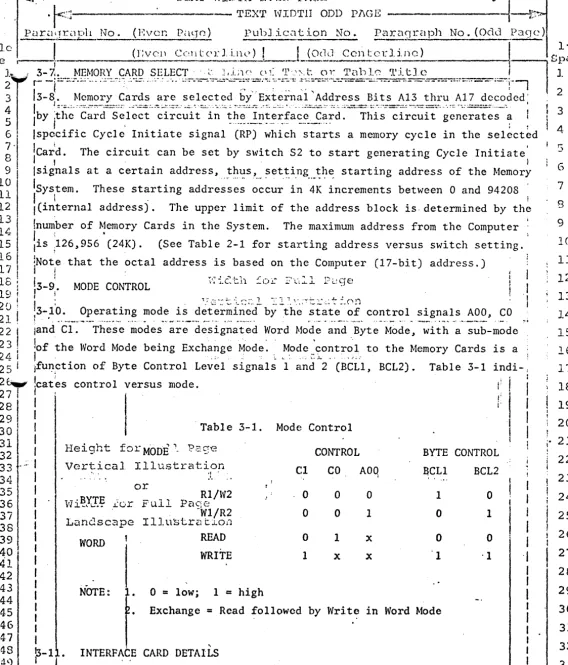
f 23 3-8. Memory Cards are selected bf .External Address Bits A13 thru A17 decoded; .
4
1
lby
'.~1~-~ ··c·~;<l=-.:5.-~ i~~~:
...
~i~~~i·t~=-i~.:~~h=~~~-!~~~~£ a-c·~~_:c;;<l :·-~=·:r1~i-~=-~-i~~~i~-. ~~~-~;~-;~·~--~a
I!
3
5
I
.
- ··- ·-·- . -· . - -··--· . .
: '
i 46 I !specific Cycle Initiate signal (RP) which starts a memory cycle in the selected
~-
lca~d.
The circuit can be set by switch S2 to start generating Cycle Initiate'1
5
I I . . l 6
9
I
!signals at a certain address, ... t~~s_, ___ ~et_!i.ng ___ ~l:~ starting address of the Memoryi~
lsys1tem. These starting addresses occur in 4K increments between O and 94208 :
12 !(internal address). The upper limit of the address block is-determined by
th~
13 '. i
1 "" /\-'. {number of Memory Cards in the System. l \ • The maximum address from the Computer .. ·
1is ,126,956 (24.K). (See Table 2-1 for starting address versus switch setting.
15 16j
i~
!
I19
!
20 \ 21
I
22 l 23!j
24 I 2:> ' ,.... i
2~
2...., I I I
281
29 3ol311
32
33 35 36 37 38 39 4041
42!Note that the octal address is based on the Computer (17-bit) address.)
I !
13-9:.
MODE CONTROL ~·;3_c:th :'.:o!:'::·-..-,:l
Fc..~ 9 ef3_1;0. Operating mode is
d~t.:~~~l~~~:l b~ lih·~:~~t·~~~=-~2
control signals AOO, CO lan.d·c-i-:-·-Th~~-~ -~od~s
...;~~--d~-~·ig~;t~d
WordMo·d-~. ~~~«i" _-'Syt~ --~1ode-, ·-~i-th -~--;~·b-~~de
,,:of the Word Mode being
Excha~ge
Mode. , !"od<c._ontro?, to the Memory Cards is a ;ifu~?tion of Byte Control Level signals 1 and 2 (BCLl, BCL2). Table 3-1 indi-,
jcat
1
es control versus mode. i:
I
: 1:
I
Table 3-1. Mode Control
I
Height for MODE.,_
Vertical Illustration
::
..or
Rl/W2
w·i~YJ:~ .L:or Full Paqe . -Wl/R2
Landscape
Illustr~tionWORD t READ
WRITE
Cl
0 0 0 l CONTROLco
0 0 1 x AOq 0 lx
x
BYTE CONTROL
8CL1
BCL2
1 0 0 1 0 1 0 ·l I I
I
I
l
I
I
·I
I
I
!!
NOTE:~·
0=
low; 1=
high~
45 • Exchange
=
Read followed by Write in Word ModeI
46 I
47 I
'1-8 '3-1 • INTERFACE CARD DETAILS 1
1
49 I f . . .
50
~-1z:·
-The J.nterfacc · Card-1s-· essentially·a-
buffcr/confi·ol Hfr-with-dataarid-~
-1~~t··
'
addt~_s_s.MY--~~~
..i_y~r
•. s/clriy.er~._
__ Car_d __ Select•·-~nd
ty_Control_, __ Mode_Control..__and_J 5 3 'f.!_mi.11g_and_C.g_n t ro l __ Circuitry:~ : ' "f--~~,~ 'Pc: ' LOrlcl P:1<·~•' No.
---~·---
----M--\ i" \ 7 8 9 10 11 12 13 1415
16 , ..., J.. I [image:12.618.11.579.17.682.2]- ~ rl'E;:rr WID'rII TWEn P.:\cg . . ·~
I .
. <,_. •
r-'.l
'J~EX~~
\HD'l'il ODD Pl\GE·+-!·J
P.:ll.:'(lqr0pli No. (Evc:r. P,:tqcj pn!>.lic'-1tion No. _£l1r6qr\:lph No. (Odd P;1q1>}l
~!c I--~
_,_J__
.
(C:'_1_".;2_1~_<-11L_edi.1w)
L_j
(Odd Ccntnrli1w)I
s~:~~~
~
V
1
~-.n~
__
,._pAT A/ ADDRgss ROUT IN_G_"~-
.~
:_·'.
7
-_~::
:!:.
~I~,:,; ~'.~-2'.;.-=-'1' ~l!
l
~~;~tJ.,,,c;
__
-'==---:-<•=~j. -~
12
I
II
.
' . . " ,, '
-~
I
23
I
i3-14. Data and Address are conveyed to/from Memory by rccei vers/dri vers in ' \~
I
h
';;~~~£ ;~~·
c:;a .. ,.
H~~~~~'::Addr~~~- Bi~~_-,;i; th;~='A17 ·c-~~t~~~~:i-;i';'";~;~:
I :
6 ·1 IA16) are processed by Memory Card Select and Starting Address Control (See:
..
I
I
~
I
:Fi~ure
3-3) to select a Cycle
-~nitiate
signal RPOO thru RP03.
,
lO !
13-15. Memory Card Select and
Sta~-ti,~g· .Add~~~-~--
Controli 1 I !
12.._ -
I l3_
I I i'6. .·13
I
;add.erMemory Card.Select and Starting Address Logic consists of a binary
U48, a 1/8 decoder U54, switch S2(1-4) and peripheral circuitry. Switch l" ' '
1
~
!
~2.is
set to the complement of the desired starting address. When thestart-.,.) I I
16
I
Jing address occurs, the complement addedio
it always equals 0000. The most~~
i
~ig~ificant
bits E4, E3 are applied to the decoder, which generates RPOO to
J.~: ; ~scl ect Memory Card 0. Subsequent addresses above the starting address add· to
;~
!
~the
_
_:~itch-_set ~!1p~t-
and J>:C:a:ise on,ly the
most_~-i~~~~ic~n
..
~
_
01:1.~.P-~~. -~-~-~~._.a.r~.
- - l
22 ! '.used, RP changes in increm~?~~ .o.~ 33~--a~o_ve the .s~~arting address. (See
23
l
!Table 2-l for starting address versus switch.set'.t~ngs.)
2 (
i
i
1 . . .. ·-· .. . : .:. .;,. ~ ..L. • • . - ·'- •;.._ -· •• - ••2 ~ . ' ( · ) I
2~'
;s-17.
PARITY CONTROL Optional •' t I27 I ' ; . I
l
28
I
0-1p.
Parity Control provides incoming data with a parity bit and checks ..out-)o
!
!going data for correct parity. The circuit includes an address select circuit3?
l
:that can be set by switch Sl(l-4) to activate parity when instructed by the
3 l i l - :· .. i -·.·." ..:.. . .- . . . . . ., - -·, - -~ ..
32
l , ..
~Computer~· ·.The Computer instruction is conveyed by Address Bi ts AOl thru Al 2~~
r
,
1cint~;naTA'oo 'th~~·A1i)··~p~1i'~d
to Par_ ity Control. Low order Bits 01 thru 04'
).:.!· I , · .
3S
1 l(i~~ernalAOO thni A03) are compared:to switch SI settings to provide the '. 36
37
n
i2
..
,
t "T
., .
..
I I -., .'. .--'. • . - •. •" ' - • • .. . - ~
jpar~ty ·select control· for the Parity-Word Multiplexer (U24, U25) and Register
l(U
3
~/-'l.J
3
6): c:~r;·,a
Zll ubtru tionI
I
t.
I _ i~-19. In even~ of a parity error in a Read word, the Parity Gencrator/Che6ke~
I
!1(Ul 7, U18) generates a parity error flag,, PB, whi"ch is sent to the Computer. J
I . - i
l1n response the Computer executes a trap t() location 114 or 116.
I
I
Il !
(See·PDP-llj
I . . '
J
I
I
I I
I
rrocessor Handblook for deta:ls of Computer Operati.on.)
I ' . .
L_._ -
---~-... -- ... _ ... __ _.. ___ ...
_.__._~---~... -- .... -.----....
-.~--I.in e 0 f •rc:d:
I
Even P.:1qc No. Center P:1q0 tro. Ocl cl P -~' <"T t; N n .
5
6
7
8
9
10 11
..
'')
.L-<
14
15
16
17
18
19
20
2l
22
23
24
25
26
27
28 29
30
31 32 33
34
35
:::~:.--.,
--- 'l'Exrr
w:nnn
ODD Pi\GE. 1---::"J
Pt1r.:11y.r·.:1ph No. (Evc~t! P._1g0) PubJic:JL:ion no. P •. 1r(·Hrraph No. {Odcl P;:-Hlf')
Jlc
:;e
l .
l?ir~;L Lin'.~
nf 1.l_',.·::t. or '1'0bl ,_ ... 'l'il:"!
(~
I
1 2?
..;
'-1·=--;,::::.-:::·::.:.--._/
~-=77·.:..:.-::.::--:.~~.-.:.::-;,.;;·; •. ·· • .;-;;·5f:cr~o~- ;~-~~-::'"- -:.-:=-~=··.:::..-:.-~~.:.~-==-=-==-=.:.-:-· --· ·-·- . ;·1
2I
;
-~·--··
... -- . -···---
I
I
I
=---=~=-~-.. ':"~'!-:..-:.:':;.;::::.-::::::::.::::::-::~-:.==-=~-::.·~=---~--:-. . -- - . ---=-':..-··-·~-:-::---.:.=.===·= .. :=-~--===:::.=~-=:..-=; 34 c: ..J r 0 7 8 9 10 11 12
131
14 I
is
I
16 I !
17;
I
18 !
19 i'
20 I
2:!.
!
22
i
22
i
I
24
I
2·
2~·
27 i 28 f
2a I
3~
I
3" I
.,~
I
33-t~-34 35 36 37 38 3940
41 42 4344
45 46 47 4S 49I
.Lk~_INTE~~~~~~-
I
I
I
I
I
I !
I
14-1. PREVENTIVE MAINTENANCE . : '.., p :-; ~-: :-:: 'l'o~\:t
I
i
. ·-·
.. -
~---.:.·----~---·-·,
14-2.
Preventive ~aintenancc consists of inspection, and cleaning as required'.IHo~ever, only cleaning of air filter should be done periodically. Inspectio~
1~ncl
cleaning of majorcom~onents
(circuit board assemblies) should be done!only when the system MUST be shut down for corrective maintenance, and then,
i .
ionly on a circuit board that MUST be removed.
I
~:· · :.
6 :: : ~ .-:·:::, r ... -. .,_, .:. J. :-:-> .J qe14-3. INSPECTION AND CLEANING
I • · · · - . -. -1 -, •
I
.
.
.~-
-..lL,.-: l .:. .,_ ... ~s·'..:.:i..~~" t.1oni .
:
.4~,4..
~.~-~ystem_ A~r .. F:ilte~·-·-·u ... ,--~--- or. -·ft·---~--·----·---·--1...
,J
I . !I' - '·
' i : . - ~ -- - --· ' - ....•.. ,
14-5. Dependent on atmospheric dust conditions, and as periodically required,i
! in~_pect, remove, and clean sy'stem air filter as· ·follows: I
1 . : Ii
I J a. Remove System front panel. ,
j I
i
b. Hold panel with dirty side down, and tap gently to loosen ,I _
accumulated dust particles. . Jc. Remove dust with vacuum cleaner, or by immersing in clean 1
!
water.I
1: c i g·n •- 1 --- -.- : '· • · · p ;=i rr r·f
• "'d~
_
~~s__
applicable, cshake out water, dry panel and filter, and · Vei t.J-re1nstall. ·~~.~· ..L ~,~:I J ·
r:·~
'4-~. B~s~plate.Connectors
I ·
I
Widti1 icr i·'uL. ;.'a:~iC:14-7_ • ., Only when Memory Card MUST be removed, inspect and clean baseplate
I , .... 1 . . . .,_ . . .L- •.. ·- ·- ... . .. - _, •.•••..•••
!connectors as required:
I :
I
a. Saturate Memory Card contacts with contact cleaner.'
l I I I I·I
I
l
fI
I
. I
I b. Insert Memory Card into and remove from baseplate connector. t
~
i.
WipJ
Memory Card connector clean with soft clean cloth. :I I
I
I
t CAUTION I
I I
I . · , I
IL Inserting anything into baseplate connector except PCB I
- - - ·could damage contact surface or change contact pressure·.-·-
··-·t ..
J4 5 6 7 8 9
I 10
11 12 13 1'1.· ,15
16
1718
19 2021
22 23 2425
26 27 28 29 3031
32 34 3SSn·· -, Never insert anything but Memory Card into baseplate
j
5
5~~--:::::::::_c_oo_n_e_c_t_o_r_.··---
.., - L:-,----··-1 _ _ _ _ _ _ _ _
l ~-: t - - - -L i I l 0. C' ! 'J' (' :-: t._...
3G
·
1.,..~·-"'-.
· - - - -
rrEXrl' WIUPll ODD Pi\GEr.~j
. '
---,~·-<l·---
,._pgxT \·IID'ril 1~\TEt-J P]\Gl~P<:1J:;:19r<1ph No 4 (r~vcr~ Paqe) Puhl.i.cc.1t:ion No_ ~u:-i.HJraph No. (Odd P;1qc~)
;!('
I
(l:v_:_i_:c,~nlcrlin")
L_J
(Ocld Ccut.erline)_J
/~~~;
~r
1_ 4 _:~-
• .. ,·=
."..~~RE~'.f
I YE_~IA.
INTENAN~~.~-~ ~;,~;2.
" ..
;::.;.~:,\:-,_~:;_:_:
__
~:~~'.:~""--_'~c
..
;;_lt:..,..c:.. ...
--""!
~
...,
r . ·'
3
I
4-h.
Correctivemaint~nance
is'he~~i11 ·u.~~ifed
to System troublcshoot}._ng, __1
the 1 2
~
I
I
goa,·:t".:;£
·-\~ht~h :i-~~\~
..
i;~-i~~·~-:-;~-~-~~t~~ --~-~-~~:· -.~i~-~~c-~:f·~;\1e~~;;~ ~~;~·:. ~h~ -··I~~-~r-f
dee '
34
6
I
I
Card or the Power Supply. Defects related to data and address can be isolated~
9
I :
to'. the data and address paths between Computer and Memory-Card memory matrixI
using a DEC PDP-11 diagnosti~_ .. (suc~ as _DZQf'..m) ._ However, to correlate Computer 10.1
~
I 1 1ocilal readouts with Memory Card address decoding, do the following: 12J_
I
II
1
. a. Construct two tables in the forms illustrated in Figtire 4-1. 13
I
I.
b. For a given Computer octal readout, fill in the appropriate
1
1
~
I
I
I·
spaces in Table A...; I l ;
16 i ! ' c. Insert binary equivalent of act.al. readout in Table A. 17
l
I!
I d. Transfer binary equivalent to Table B according to
Memory-18 I
I
j . ..· Card interval bit positions. .. ·' ·
1 ~~
j
·I · · · ·2 C ;
! .
e. Refer to Memory Card Technical Manual TM929162, Section I I I21. ; : .. )--·----.for theory of address decoding. _ .
---·---·---·--~·-···-·--··---·-···
22 :I
·
f. Note that the decoding of Interval Address bits 15 and 1623 I
I
i
represent RP Select: each RP selected.selects a Memory;~
; : 1
·
Card. (See Theory, Section II I.) (Figure 4-2 illustrates~ relationship among external Address
(A),
Address Input (AI) 22-: l. f
I
and Memory Address (MA) . )I
I
I! •
28
1
4-10. Computer designated data bits (BD) also do not correspond·exactly'to29
I I
:
30
!
!Me~ory System interval data bits. To correlate Computer to Memory data bits 31I :
refer_J:o Table 4-1._,_:_::_ l)CJge~ ~
L ._
i
!
"Tr, •. - ·= - -· ·• •· .,~
.. · ,_ ··-- .i.- ; --n- :;,
14-11_; - MEMORY CARD SELECT _ ... _,,
..., 1 I
.;) ... ! ("'! ~- i
!
3S ·
i
4-~2~"licr-N~ ~~-m-~r~ ~f~~d }:~~;~~elected
(addressed) by UNIBUS Address Bits A17 and~*I
f Al6 ... Table 4-2 designate's UNIBUS Address Bit configurations for selecting~ ~
l
ea~h
1~~;;~;~t"a;d S'i~t: •-'-~~ "'~~~'
this chart, subtract the starting address ofth~·Memory System from the UNIBUS address. The resulting binary states of, 40
41
4~
43
44 45
4G.
47 48
~1~1 I
r·
["'"\
. )
-i
Address Bits Al7 and Al6 correlate to the selected card slot. . .
...
...
'
\
,
i
'
I
I
I
I
I
I I
I
L ..- - -- ..__. - ... ~:.. .... ...__ -- ~ ~ ... - . - i - - . . . - - . . . - . . . _ . . . _ . . . _ - - . . . _ - . . . . - . _ . . . - . . . . - . -_ . . . . . _ . ..J
~~rr·-
... ,
53
L..---~J~,~~~1~_,t~~...:..r.~i~n~r.~._c~'~f__.;1_'r~.'~~·:~t __________________ ~~~--~Odd I'd
rrc
Nn.8
9 JO
11
,
~)..
. ._,
-_,..;.... -~
Jlj.
15
16
l'/
18
19
2C>
21
22
23
24
25
26
27
28 29
30
31
32
33
3'1
3S
'""t"'I . .
I
• t . L . 1 - ' . l . l J L,Vl'd.'J J•i\\..:Jl'.1 ... , .. . j<.::
.
·rr-;x·r
WID'l'II ODD Pi\GE1--~:>
P<1r~1gr~1ph No. (F:v0r. P.'.Jrre) Pnblic;.1tion No. Pr:u:nqr<H?h No. (Odd P;1qc~)
.. - - - . - - - 1-1/2
;;~c:
___
L·-·---~---~l·:~c.·~_::_~~~~:.~7J. i.:_~·l
..
i. ___
j
(0•!:2__ Cen toi:linc')I ·.
GpnC<'>')
r~-13.
'. INTERFACE CAHD TROUBLESIJOOTING ' '.'~~t: ()J~
'.i.'<i1Jle 'Pi tlcI~
12~ r- - :-:.:::· ... ;n .;::: ~: • :..:. -.. -:.··· ... - ... :. : : ·=-- ·:;..:.: "': ~;· .. -:· .. ~; · ... - --: . ; ... , .. _ -; ~-~· ... -: ~ .. ;.-';'::~-;;: .·:··.::::..-.:.":.-.:.::.;. -;.-=--=~-;.~.;:;.-==·=.::-::=--:-:.-:-=--:::::-=--=:::.-.;::r ···..,
I
:; 4-i4. '. Mal functions common to all
Mcmo~y
Cards' nre most likely traceable to the . ; 2L I '. ·... ·.;-;- .. :· .... ~ '.~.:. :·:. . :·"7.:-"'.'.- •• ~ .".=.::: ::·:'.· ~-.c~:-.• -.- :· .... •.: . . .• ···:.- ; ·:.. ·.-.-:~·:-:. : ... . "'..:::..'". ::;-:.-.~-::=~···:·.:.~ .. , -.·. ·.: ··: :·.-:. ;;;·::::: ·:~·- ·.:· •. ·~:~· ::.-·...: -· I 3
5
In Te r ~ace Ca rd . All data and addr_e_s ~ ~ ~ ~:5_
_'.l_r_e ___ r_ou t ed through this Card; thus ; 1I
6 ;re~atcd buffers can be suspected in event of data and address failures. Simi- 4-. I I .
~ llarly ,· the Parity circuit (when included) services all Memory Cards. .
0
I
I i iI
l~
j4-f
5.~ Card-sele~tion
problems ca·n .. beisolate-~(
by
interchanging Memory Cards ..i J_ ;continued malfunction of the apparently defec.ti ve Memory Card indicates this
t;
;ca~d
is defective. If the substituted ca:rd fails, the Interface Card isL4
~efeciive.
!
i .
. I ; I
LS ; I ! f
LE :4-~6. MEMORY CARD MODIFICATION 1
t_ 7
i
i
i ~i_t: 4-17. · To c:.cconunodate the PDP-11 Computer System, the MICROMEMORY 3000QD Memory
c . ! .
_.; Cards are modified as follows:_ ;;: _- \: _·.c:.1 I lj_ ~:<:>::.r~. t ion
:(; l I \
1
1
l
i ...
:-·'.-B~f-:.:
..
Tl':.1.~~-9~.~-2_:
- - · -
or
.. .
-·~I; ~I
i( Pag1
le
2-10.Pl-?_O,·-~~?:S~ Ail~ ~-·,_.,_J
.. lp~~qe
4-. L~ ... '.}1·s.:. AI14 · -; -~ ... :-1- ... -"::l.'-i' on
(,..4 "' " t.,...l. .... _. ...._ ....4. .·:- o.I . . . . ..L _._ ... •' ' -.s... "-"' ' - •
~~
.., I
1
I
f
7'¥
sf
('. i _, I
Ol
i
I
:· ! I
Lj 3 , __ ,. ..
l
~~
I I
s
i
I
6 t
I
7
I
3 I
~
l
) I L
I
j
I
I
I
Pl-64, Was AI14
Is RDAG
I
SectionV,
Schematic 929668l
i
If
Sheet 1.
Pl-70;
Pl-64. Same as P2-i0 above Height for t:1'.! i .. : ~)acr2
Sheet 7. -- Zone AS, Was AI 15 to 70 VerticaJ Ill~~tr~tion
RDAG to 64
or .
-sheet 8 •. Zone CB, :Was AI14 to 64
Width for Full P~ge· '
.. Is AI14 to 10·
LandscLJpe
IllustrationI
I I
: "• :,1'i
- l
I
I
I
.j
I
I
I
.1I
I
I
I
I
I
I
I
I
I I I
I
t I
I
I \ 1
.
. "- IL __ . ....; ___
4'.f _ _ _ _ - - - - _ _ _ _ _:_ _______ · - - - ...Jr
I
.
I
l~vcn Paq0 No. Center Puqe No. Odd Pt-lqc No.
6
7
8
9
10
LL
12
;· 13 14 15
16
17
18
19
20
21
22
23
24
25
26
27
28 29 30
31
32
33
34
35
···1 · . . .
• - " • · • I ' \ . '.
Table A. Octal to Binary Conversion
. ;
·~ .~~=.'..:_'
~ ·~..
~---·.. --- ·- ··-· ··-
l' .. -.
,._,/
.' i.OCTAL READOUT
-.. ·-- -· . ·-·· -. -·.BINARY EQUIVALENT
. -.~-... ... -~ ...
INT ADD BITS
16 15 14 13 12 11 10 .9. 8 7 6 5 4 3 2 1MEM CARD INT BITS
2 0 1 8 1114
7 10 9 3 12 13 4s
Table B. Binary Reorganization
MEM.CARD INT
BITSBINARY
(From TableA)
14 13 12 11 10 9 8 7 6 5 4 3 2 l
Figure 4-1. Computer Octal to Memory~Card Binary Conversion Chart
. · .. : c;~ -_
. -. . . ---· ...
·Table 4-1_. Data Bit Correlation
BUS DATA
BITS 15 14 13 12 1110
9 8 7 6 5 4 3 2 1"'-th/DO BITS 17 2 16 15 14 13 12 11 10 9 7 6 5 4 3 .. 8 1
PARITY
P2Pl
-·;,...'
Table 4-2. Mem?ry Card Select Chart
UNIBUS.
*
i'SELECTED
ADDRESS BITS
CARD SLOT
A17 A16
-0 0 B
0 1
c
1 0 D
l 1 E
AI16 AUS Note:
MEMORY INTERNAL
1.*
1 = Low; '0 = HighADDRESS BITS
2.**
1=
High;
0=
Low: :. !. ..! : • ~·)
~ t ' I . .
0
6
0
0
[image:17.631.16.577.53.779.2]