C-CUBE MICROSVSTEMS
92 -6000-001
C-CUBE MICRDSYSTEMS
This document is preliminary. The specifications contained herein are derived from functional specifications and performance estimates, and have not been verified against production parts.
C-Cube Microsystems reserves the right to change any products described herein at any time and without notice. C-Cube Microsystems assumes no responsibility or liability arising from the use of the prod-ucts described herein, except as expressly agreed to in writing by C-Cube Microsystems. The use and purchase of this product does not convey a licence under any patent rights, copyrights, trademark rights, or any other intellectual property rights of C-Cube Microsystems.
Trademark Acknowledgment:
The C-Cube corporate logo is a registered trademark of and C-Cube MPEG Video Lab is a trademark of C-Cube Microsystems.
Vectra is a trademark of Hewlett-Packard Company.
Maynard and MaynStream are registered trademarks of Maynard Elec-tronics, Inc.
Microsoft, MS-DOS, and Windows are registered trademarks of Mi-crosoft Corporation.
Bogart image © 1992 Bogart, Inc. Used under license authorized by Curtis Management Group, Indianapolis, Indiana, USA
© C-Cube Microsystems 1992 All rights reserved
C-Cube Microsystems 1778 McCarthy Boulevard
Milpitas, CA 95035 Telephone (408) 944-6300
Preface
This guide is the primary source for installation and operation informa-tion for the C-Cube MPEG Video Lab.
This guide describes Revision B of the MPEG Video Decoder Board
Applicability
and Version 1.2 of the Playback software.
This guide is intended for:
o System designers and managers who are evaluating the MPEG Video Lab for use as a development vehicle for MPEG applica-tions
o Programmers and software engineers who are writing application programs that interact with the MPEG Video Decoder Board used in the MPEG Video Lab
Audience
This guide is divided into these chapters:
Organization
o Chapter 1, Introduction, describes the hardware and software that comprise the MPEG Video Lab.
o Chapter 2, MPEG Overview, presents an overview of MPEG de-coding.
o Chapter 3, Installation, tells how to install and power up the MPEG Video Lab.
o Chapter 4, Using the Playback Software, describes the use of the playback application supplied with the MPEG Video Lab. It in-cludes a tutorial that can be worked in about 15 minutes.
o Chapter 5, The MPEG Video Decoder Board, gives a functional description of the board. It also contains programming informa-tion about the board-level registers.
o Appendix A, Encoding Guidelines, gives information for creating coded bitstreams.
o Appendix B, MPEG Video Lab Files, describes the files supplied with the MPEG Video Lab.
Related
The MPEG standard is described in detail in Coded Representation ofPublications
Picture, Audio and Multimedia/Hypermedia Information, ISO/IEC JTClISC 29, December 6, 1991.
Conventions
Please note the following conventions that are used in this manual:o Hexadecimal numbers are indicated by the prefix Ox, for example, OxFF. Binary numbers are indicated by a subscript, for example,
102. Otherwise, all numbers used in this guide are decimal num-bers.
1 Introduction
1.1 Video Lab Components 1.2 Sample Bitstreams
1.3 Video Lab Documentation Set 2 MPEG Overview
2.1 MPEG Stream Structure 2.1.1 MPEG Stream Structure 2.1.2 General Decoding Process 2.1.3 Video Stream Data Hierarchy 2.2 Inter-picture Coding
2.2.1 Picture Types
2.2.2 Video Stream Composition 2.2.3 Motion Compensation 2.3 Intra-picture (Transform) Coding 2.4 Synchronization
2.4.1 System Clock References 2.4.2 Presentation Time Stamps 3 Installation
3.1 Contents
3.2 Installation Procedure
Contents
1-1 1-3 1-3 2-2 2-2 2-2 2-3 2-6 2-6 2-7 2-8 2-10 2-11 2-11 2-12 3-1 3-24 Using the Playback Software
4.1 Tutorial 4-1
4.1.1 Starting the Playback Software 4-2
4.1.2 Playing Back a Video Sequence 4-4
4.1.3 Pausing, Resuming, and Single-frame Advancing 4-8
4.1.4 Fast-Forward and Slow-Motion 4-9
4.1.5 Ending a Playback Session 4-10
4.2 Reference Guide 4-11
4.2.1 The Development Window 4-11
4.2.2 The Player Window 4-12
4.2.3 The Remote Window 4-14
4.2.4 The Bitstreams Selection Window 4-16
4.3 Using Scripts 4-17
4.3.1 Creating a Script 4-17
4.3.2 Running a Script 4-18
5 The MPEG Video Decoder Board
5.1 Overview 5-1
5.2 Functional Description 5-2
5.2.1 MPEG Processor 5-3
5.2.2 EISA Interface 5-3
5.2.3 Coded Data FIFO 5-3
5.2.4 DRAM 5-3
5.2.5 Color Space Converter 5-4
5.2.6 Video DAC 5-4
5.2.7 Raster liming Generator 5-4
5.2.8 Line Store 5-4
5.3 Operation Overview 5-4
5.4 Programmer's Model 5-6
5.4.1 EISA Product ID Register 5-7
5.4.2 Configuration/Status Register 5-7
5.4.3 Base Address Register 5-9
5.4.4 Decoder RREG and GREG Registers 5-9
5.4.5 DRAM Address Register 5-10
5.4.6 DRAM Data Register 5-10
5.4.7 Coded Data FIFO Reset Register 5-11
5.4.8 Coded Data FIFO 5-11
5.5 Other System Applications 5-12
5.5.1 System Design Considerations 5-12
5.5.2 Installation Guidelines 5-12
5.6 Specifications 5-14
5.6.2 Interface Specifications 5.6.3 Video Display Formats
Appendix A Encoding Guidelines
A.l MPEG Draft Standard Compliance A.2 8itstream Naming Conventions
Appendix B MPEG Video Lab Software Files
8.1 Software Files
8.2 704 Files From Previous Versions
5-14 5-15
A-1 A-2
8-1 8-3
1-1 Video Lab Components
2-1 General MPEG Decoding System 2-2 MPEG Data Hierarchy
2-3 Location of Luminance and Chrominance Values 2-4 Macroblock Composition
2-5 Forward Prediction 2-6 Bidirectional Prediction
2-7 Typical Display Order of Picture Types 2-8 Video Stream versus Display Ordering 2-9 Transform Coding Operations
2-10 SCR Flow in MPEG System 3-1 Cabling Diagram
4-1 Playback Software Initial Screen 4-2 Player and Remote Windows 4-3 Bitstreams Selection Window 4-4 Play Button Active
4-5 Remote Window During Play Sequence 4-6 Remote Window at End of Video Sequence 4-7 Remote Window During Pause
4-8 File Menu
Figures
1-2 2-3 2-3 2-4 2-5 2-6 2-7 2-8 2-8 2-11 2-12 3-2 4-2 4-3 4-4 4-5 4-6 4-7 4-9 4-104-9 Exit Windows Dialog Box
4-10 Development Window Operations 4-11 The Player Window
4-12 The Remote Window
4-13 The Bitstreams Selection Window
5-1 MPEG Video Decoder Board Block Diagram 5-2 MPEG Video Decoder Board Address Map 5-3 Analog Video Output Connector
B-1 Directory Structure Showing MPEG Video Lab Files
3-1 MPEG Video lab Shipping Boxes 5-1 VF Field Values
5-2 CF Field Values 5-3 Video Display Formats
B-1 Bitstream Files Supplied with MPEG Video lab
Tables
3-1 5-8 5-8 5-15 B-3
Chapter
1
Introduction
The MPEG Video Lab provides the tools needed to decode and preview MPEG bitstreams at bit rates up to 8 Mbits per second. It supports these video formats:
o NTSC: from 352 x 240 to 704 x 480 at 30 Hz
o PAL: from 352 x 288 to 704 x 576 at 25 Hz
The MPEG Video Lab also supports RGB video output format.
This chapter describes the components of Video Lab and discusses the documentation and sample bit streams provided with the MPEG Video Lab.
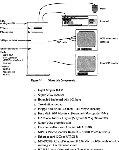
The basic MPEG Video Lab system shown in Figure 1-1 is based on the 1.1
HP486/33TVectra™ personal computer, which uses the EISA bus. The Video Lab standard configuration includes the following components (supplier is Components Hewlett-Packard except where noted otherwise in parentheses):
Video Lab Components
Mouse
486 PC
w/8MbytesRAM _ _ ...
.r--...I-...&..,
KeyboardOATdrive ---+~
I----~
3.5" floppy drive ----+-I~
-,---,
670 Mbyte hard disk ---Hl~:
l
NTSC video monitor(optional) ._---'"
Internal Components - ___ ~
• Cards: SuperVGA EI SA Controller MPEG OecoderBoard Ethernet
• Software: DOS 5.0 Windows 3.0
PC-NFS
[image:15.508.32.448.72.595.2]Super VGA monitor
Figure 1-1 Video Lab Components
o Eight Mbytes RAM
o Super VGA monitor
o Extended keyboard with 101 keys o Two-button mouse
o Floppy disk drive: 3.5-inch, 1.44 Mbyte capacity o Hard disk: 670 Mbytes unformatted (Micropolis 1624) o DAT tape drive: 2 Gbytes (Maynard® MaynStream®) o Super VGA graphics card
o Disk controller card (Adaptec AHA 1740)
o MPEG Video Decoder Board (C-Cube® Microsystems) o Ethernet card (3Com W!RG58)
o Board driver software (C-Cube Microsystems) o Sample bitstreams
o Complete documentation
Options are an RGB video monitor and the C-Cube MPEG encoder software.
C-Cube Microsystems supplies a variety of sample bitstreams with Vid-eo Lab to demonstrate the basic operation of the system for a range of resolutions. Appendix B summarizes the bitstreams provided. You can use these bitstreams for demonstrations and product development.
Your system may also include some bitstreams not listed in Appendix B. These extra bitstreams may have restrictions on their use. Contact C-Cube Microsystems for more information.
This guide is the primary source of the information needed to operate Video Lab. However, you may need to refer to manuals that provide more detailed information about some of the MPEG Video Lab compo-nents. C-Cube Microsystems supplies with the MPEG Video Lab a complete set of documentation for all the major components in the sys-tem. The manuals supplied with the MPEG Video Lab are listed below.
o Setting Up Your HP Vectra 486/33T (Hewlett-Packard)
o Dl182 Video Graphics Color Display installation Guide (Hewlett-Packard)
o Super VGA Board User's Manual (Hewlett-Packard)
o Dealer Configuration File Creation Guide (Hewlett-Packard)
o MaynStream DOS User's Manual (Maynard)
o ASPI Manager InstaLLation Guide (Adaptec)
o ASPI MS-DOS Manager Software Manual (Adaptec)
o AHA-174x Family Configuration & Download Utilities Software Manual (Adaptec)
oMS-DOS 5.0 User's Guide & Reference (Hewlett-Packard) oMS-DOS 5.0 Getting Started (Hewlett-Packard)
o Windows User's Guide (Microsoft)
Sample Bitstreams 1.2 Sample Bitstreams 1.3 Video Lab Documentation Set
Video Lab Documentation Set
Chapter 2
MPEG Overview
This chapter presents an overview of the Moving Picture Experts Group (MPEG) standard that is implemented by the MPEG Video Lab.The standard is officially known as ISO/lEC Draft Standard "Coded repre-sentation of picture, audio and multimedia/hypermedia information," CD 11172, December 6, 1991. It is more commonly referred to as the
MPEG standard.
MPEG addresses the compression and decompression of video and au-dio signals and the synchronization of auau-dio and video signals during playback of decompressed MPEG data. The MPEG video algorithm can compress video signals to about 1/2 to 1 bit per coded pixel. At a com-pressed data rate of 1.2 Mbits per second, a coded resolution of 352 x 240 at 30 Hz is often used, and the resulting video quality is comparable to VHS.
MPEG Stream Structure
2.1
MPEG Stream Structure
This section explains the general structure of an MPEG stream and in-troduces some basic concepts used in the rest of the chapter.
2.1.1 MPEG Stream Structure
In its most general form, an MPEG stream is made up of two layers:
o The system layer contains timing and other information needed to demultiplex the audio and video streams and to synchronize audio and video during playback.
o The compression layer includes the compressed audio and video streams.
2.1.2 General Decoding Process
Figure 2-1 shows a generalized decoding system.
The system decoder extracts the timing information from the MPEG stream and sends it to the other system components. (Section 2.4, Syn-chronization, has more information about the use of timing information for audio and video synchronization.) The system decoder also demul-tiplexes the video and audio streams and sends each to the appropriate decoder. In many applications, the system decoder function is imple-mented as a software program on the host computer.
The video decoder decompresses the video stream as specified in Part 2 of the MPEG standard. (See Section 2.2, Inter-picture Coding, and Sec-tion 2.3, Intra-picture Coding, for more informaSec-tion about video com-pression.)
MPEG System stream - - - . Decoder
Video decompressed Decoder - - - . video
[image:20.507.43.451.320.564.2]Audio decompressed Decoder - - - . audio
Figure 2-1 General MPEG Decoding System
2.1.3 Video Stream Data Hierarchy
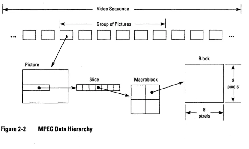
The MPEG standard defines a hierarchy of data structures in the video stream as shown schematically in Figure 2-2.
Video Sequence
Group of Pictures
-I
MPEG Stream Structure
...
~reD'
---..-1.
1DDDDDDDD
Block
Slice Macroblock
-t
8
II!Q~
Figure 2-2 MPEG Data Hierarchy
MPEG Stream Structure
Video Sequence
Consists of a sequence header, one or more groups of pictures, and an end-of-sequence code. The video sequence is another term for a video stream as defined above.
Group of Pictures
A series of one or more pictures intended to allow random access into the sequence.
Picture
The primary coding unit of a video sequence. A picture consist of three rectangular matrices representing luminance (Y) and two chrominance (CbCr) values. The Y matrix has an even number of rows and columns. The Cb and Cr matrices are one-half the size of the Y matrix in each di-rection (horizontal and vertical).
Figure 2-3 shows the relative x-y locations of the luminance and chrom-inance components. Note that for every four lumchrom-inance values, there are two associated chrominance values: one Cb value and one Cr value. (The location of the Cb and Cr values is the same, so only one circle is shown in the figure.)
o
0
•
o
0
o
0
•
o
0
o
0'
•
o
0'
o
0
•
o
0
(t) = Cb, Cr value
o
0
•
o
0
o
0
•
o
0
o
=YvalueSlice
One or. more contiguous macroblocks. The order of the macroblocks within a slice is from left to right and top to bottom.
Slices are important in the handling of errors. If the bitstream contains an error, the decoder can skip to the start of the next slice. Having more slices in the bitstream allows better error concealment, but uses bits that could otherwise be used to improve picture quality.
Macroblock
A 16-pixel by 16-line section of luminance components and the corre-sponding 8-pixel x 8-line section of the chrominance components. See Figure 2-3 for the spatial location of luminance and chrominance com-ponents. A macroblock contains four Y blocks, one Cb block and one Cr block as shown in Figure 2-4. The numbers correspond to the order-ing of the blocks in the data stream, with block 1 first.
y Cb Cr
Figure 2-4 Macroblock Composition
Block
A block is an 8 by 8 set of values of a luminance or chrominance com-ponent. Note that a luminance block corresponds to one-fourth as large a portion of the displayed image as does a chrominance block.
MPEG Stream Structure
Inter-picture Coding
2.2
Inter-picture
Coding
Much of the information in a picture within a video sequence is similar to information in a previous or subsequent picture. The MPEG standard takes advantage of this temporal redundancy to represent some pictures in terms of their differences from reference picture. This section de-scribes the picture types and explains the techniques used in inter-pic-ture coding.
2.2.1 Picture Types
The MPEG standard specifically defines three types of pictures: intra, predicted, and bidirectional.
Intra Pictures
Intra or I-pictures are coded using only information present in the pic-ture itself. I-picpic-tures provide random access points into the compressed video data. I-pictures use only transform coding and therefore provide moderate compression. I-pictures typically use about two bits per coded pixel.
Predicted Pictures
Predicted or P-pictures are coded with respect to the nearest previous l-or P-picture. This technique is called fl-orward prediction and is illustrat-ed in Figure 2-5. Prillustrat-edictillustrat-ed pictures provide more compression and serve as a reference for B-pictures and future P-pictures. P-pictures use motion compensation to provide more compression than is possible with I-pictures. P-pictures can propagate coding errors, since P-pictures can be predicted from previous P-pictures.
Forward Prediction
Bidirectional Pictures
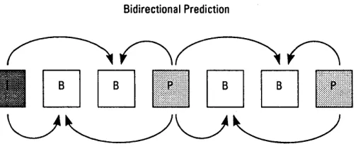
Bidirectional or B-pictures are pictures that use both a past and future picture as a reference. This technique is called bidirectional prediction and is illustrated in Figure 2-6. Bidirectional pictures provide the most compression and do not propagate errors because they are never used as a reference. Bidirectional prediction also decreases the effect of noise by averaging two pictures.
[image:24.504.56.309.189.308.2]Bidirectional Prediction
Figure 2-6 Bidirectional Prediction
2.2.2 Video Stream Composition
The MPEG algorithm allows the encoder to choose the frequency and location of I-pictures. This choice is based on the application's need for random accessibility and the location of scene cuts in the video se-quence. In applications where random access is important, intra pictures are typically used two times a second.
The encoder also chooses the number of bidirectional pictures between any pair of reference (I or P) pictures. This choice is based on factors such as the amount of memory in the encoder and the characteristics of the material being coded. For a large class of scenes, a workable ar-rangement is to have two bidirectional pictures separating successive reference pictures. A typical arrangement of 1-, P-, and B-pictures is shown in Figure 2-7 in the order in which they are displayed.
Inter-picture Coding
Inter-picture Coding
2 a-pictures between referenXictures
1 second
I-picture every 15th frame (1/2 second)
IBBPBBPBBPBBPBBIBBPBBPBBPBBPBB 1 2 3 4 5 6 7 8 9 10 11 12 13 14 15 16 17 18 19 20 21 22 23 24 25 26 27 28 29 30
Figure 2-7 Typical Display Order of Picture Types
The MPEG encoder reorders pictures in the video stream to present the pictures to the decoder in the most efficient sequence. In particular, the reference pictures needed to reconstruct B-pictures are sent before the associated B-pictures. Figure 2-8 demonstrates this ordering for the first section of the example shown above.
Display Order
2 3 4 5 6 7
Video Stream Order
4 2 3 7 5 6
Figure 2-8 Video Stream versus Displav Ordering
2.2.3 Motion Compensation
When a macroblock is compressed by motion compensation, the com-pressed file contains this information:
o The spatial difference between the reference and the nlacroblock being coded (motion vectors)
o The content differences between the reference and the macroblock being coded (error terms)
Not all information in a picture can be predicted from a previous pic-ture. Consider a scene in which a door opens. The visual details of the room behind the door cannot be predicted from a previous frame in which the door was closed. When a macroblock in a P-picture cannot be represented by motion compensation, it is coded in the same way as a macroblock in an I-picture, that is, by transform coding techniques (see Section 2.3, Intra-picture Coding).
Macroblocks in a B-picture can be coded using either a previous or fu-ture reference picfu-ture as a reference, so that four codings are possible:
o Intra coding: no motion compensation
o Forward prediction: the closest previous 1- or P-picture is used as a reference
o Backward prediction: the closest future 1- or P-picture is used as a reference
o Bidirectional prediction: two pictures are used as reference, the closest previous 1- or P-picture and the closest future 1- or P-pic-ture
Backward prediction can be used to predict uncovered areas that do not appear in previous pictures.
Inter-picture Coding
Intra-picture (Transform) Coding
2.3
Intra-picture (Transform) Coding
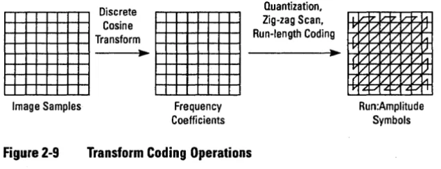
The MPEG transform coding algorithm includes these steps:
o Discrete cosine transform (DeT)
o Quantization
o Run-length encoding
Both image blocks and prediction-error blocks have high spatial redun-dancy. To reduce this redundancy, the MPEG algorithm transforms 8 x 8 blocks of pixels or 8 x 8 blocks of error terms to the frequency domain with the Discrete Cosine Transform (DCT).
Next, the algorithm quantizes the frequency coefficients. Quantization is the process of approximating each frequency coefficient as one of a limited number of allowed values. The encoder chooses a quantization matrix that determines how each frequency coefficient in the 8 x 8 block is quantized. Human perception of quantization error is lower for high spatial frequencies, so high frequencies are typically quantized more coarsely (Le., with fewer allowed values) than low frequencies.
The combination of DCT and quantization results in many of the fre-quency coefficients being zero, especially the coefficients for high spa-tial frequencies. To take maximum advantage of this, the coefficients are organized in a zigzag order to produce long runs of zeros (see Figure 2-9). The coefficients are then converted to a series of run-amplitude pairs, each pair indicating a number of zero coefficients and the ampli-tude of a non-zero coefficient. These run-ampliampli-tude pairs are then coded with a variable-length code, which uses shorter codes for commonly oc-curring pairs and longer codes for less common pairs.
Quantization,
•
:~~~~;:
•
Ru~~~~:;~~~ing
_
----~.~ ---~.~~
[image:28.508.43.361.88.210.2]Image Samples
Figure 2-9
Frequency Coefficients
Transform Coding Operations
Run:Amplitude Symbols
Synchronization
The MPEG standard provides a timing mechanism that ensures syn.;.
2.4
chronization of audio and video. The standard includes two timing pa- Synchronization rameters used in the MPEG Video Lab: the system clock reference
(SCR) and the presentation time stamp (PTS).
The MPEG system clock running at 90 kHz generates 7.8 x 10⁹ clocks in a 24-hour day. System clock references and presentation time stamps are 33-bit values, which can represent any clock cycle in a 24-hour pe-riod.
2.4.1 System Clock References
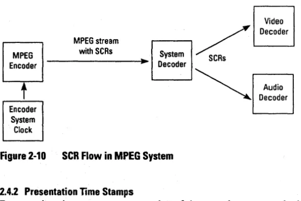
A system clock reference is a snapshot of the encoder system clock. The SCRs used by the audio and video decoder must have approximately the same value. To keep their values in agreement, SCRs are inserted into the MPEG stream at least as often as every 0.7 seconds by the MPEG encoder, and are extracted by the system decoder and sent to the audio and video decoders as illustrated in Figure 2-10. The video and audio decoders update their internal clocks using the SCR value sent by the system decoder.
Synchronization
Video
MPEG stream with SCRs
r---. . / Decoder
System < s MPEG
Encoder ---I~~ Decoder
t
[image:29.510.145.440.83.280.2]Encoder System Clock
Figure 2-10 SeH Flow in MPEG System
2.4.2 Presentation Time Stamps
Audio Decoder
Presentation time stamps are samples of the encoder system clock that are associated with some video or audio presentation units. A presenta-tion unit is a decoded video picture or a decoded audio time sequence. The encoder inserts PTSs into the MPEG stream at least as often as ev-ery 0.7 seconds. The PTS represents the time at which the video picture is to be displayed or the starting playback time for the audio time se-quence.
Chapter 3
Installation
The MPEG Video Lab is shipped with all hardware components prein-stalled and all software loaded on the system hard disk. This section de-scribes how you connect the major components and start the system for the first time.
The MPEG Video Lab is shipped in three boxes. The contents of each box is summarized in Table 3-1.
Table 3-1 MPEG Video Lab Shipping Boxes Box Size
30 x 26 x 20 18x17x15 12x12x12
Wt.lbs(kg)
83(37.3) 28(12.6) 30(13.6)
Contents Vectra PC and cables Monitor
Documentation and software
3.1 Contents
Installation Procedure
3.2
Installation
Procedure
Follow these instructions to install the MPEG Video Lab:
II Unpack all boxes and check the contents against the list in Table 3-1. If anything is missing, contact C-Cube Microsystems imme-diately.
II Locate the HP Vectra personal computer, the VGA monitor, video monitor, keyboard, and mouse. Make sure you have access to the rear of the Vectra and the monitors.
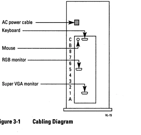
II Connect the cables to the rear panel of the Vectra as shown in Fig-ure 3-1.
II Tum on the power on the monitors and the Vectra.
The system should boot up automatically and should end with Windows running.
If the system boots up to Windows, you can proceed to the next chapter to learn how to use the playback software. If it does not boot up to Win-dows, call C-Cube Microsystems.
AC power cable ----+~:l1 Keyboard
---1---,
C Mouse _ _ _ _ _ _ ~B~
8
RGB monitor _ _ _ _ _ - t -7-t-.
6
5
4
[image:31.504.149.386.314.541.2]Super VGA monitor ---f-..::~~---. 1 A
Figure 3-1 Cabling Diagram
Chapter
4
Using the Playback
Software
This chapter describes the use of the playback software to preview bit-streams on the MPEG Video Lab system. This chapter includes a tuto-rial and a reference section.
This section teaches you the basic operations of the playback software. You'll get the most benefit from these instructions if you perform the steps as you read. You can complete this tutorial in about 15 minutes.
Actions that you are expected to take are indicated by a check mark as shown in this example:
~ Click the Cancel button.
Unless otherwise stated, all mouse button operations in this guide use the left mouse button.
Pressing the return key is represented by
<return>
4.1
Tutorial
Tutorial
4.1.1 Starting the Playback Software
The instructions in this section show you how to start the playback soft-ware once the system is powered up. If the system is powered up cor-rectly, you should see the screen display shown in Figure 4-1.
File Qptions Window ~elp
VideoLab
[image:33.505.64.449.136.400.2]Main Microsoft QClWin Games Accesories
Figure 4-1 Plavback Software Initial Screen
Proceed with the following steps to work the tutorial.
t/ Double-click anywhere on the icon labeled "VideoLab" using the left mouse button.
t;lJ
MPEG Playerala
File Qptlons ,!:!elp
II
QuitI
~ Repeat
0
PALIDD~I
~~~ [image:34.505.49.468.80.359.2]Main Microsoft QClWin Games Accesorlea
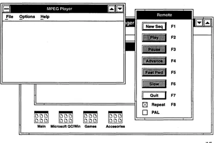
Figure 4-2 Player and Remote Windows
The Player window displays status messages about the operation of the playback software. The Remote window includes the controls used to operate the playback software. Both are standard windows in Windows 3.0, which means that you can move, iconify, close, and open them us-ing Windows commands. (To learn how to use Windows commands, see the Microsoft Windows documentation supplied with your system.)
Examine the Remote window. The captions for all buttons except the New Seq and Quit are shaded gray. A gray-shaded caption shows that a
Tutorial
F2
F3
F4
F5
F6
F7
Fa
VL-02
Tutorial
button is inactive. When a button is inactive, you can't operate it. Only the buttons with black captions are active.
4.1.2 Playing Back a Video Sequence
The instructions in this section show you how to choose a bitstream, start and stop the playback, and set the option for repetitive playback. These operations use the New Seq, Play, and Stop buttons, and the Re-peat checkbox. (The New Seq button changes to Stop when you start playing a video sequence.)
t/ Click New Seq.
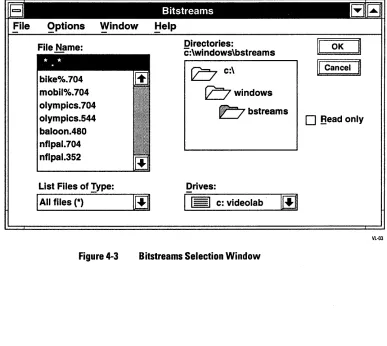
The Bitstreams Selection window appears as shown in Figure 4-3.
File Qptions Window ~elp
File Name:
bike%.704 mobil%.704 0lympics.704 0lympics.544 baloon.480 nflpal.704 nflpal.352
List Files of Type:
I
All files (*)-Figure 4-3
100
Directories:
c:\windows\bstreams
b
C:\bwindows
~bstreams
Drives:
Bitstreams Selection Window
OK
II
Cancelo
Bead only [image:35.504.63.450.242.588.2]The Bitstreams Selection window shows the bitstreams that are avail-able for previewing.
II' Double-click on the bitstream "nfl.704".
The Bitstreams Selection window disappears. The Player window dis-plays the message:
Selected file: c\mpeg\bstreams\nfl.704
The Play button in the Remote window is now active as shown in Figure 4-4.
II
NewSeqI
F1 Play ButtonII
PlayI
F2Active
F3 F4
F5
F6
II
QuitI
F7IZ1
Repeat F80
PAL [image:36.507.53.229.220.473.2]VL·04
Figure 4-4 Play Button Active
ttl Click Play.
Tutorial
Tutorial
The Player window displays a series of messages:
Clearing decoder memory ... Initializing decoder .. . Microcode being loaded .. .
*** Ready to play sequence ***
After the last message, the video sequence begins to play on the video monitor. The Remote window has several changes, as shown in Figure 4-5.
F1
Play Button --+HI~
Inactive F2
F3
F4
Buttons
Active~-""'",,-_ _ ... F5
Slow F6
Quit F7
Repeat Fa PAL
[image:37.508.152.340.206.441.2]Vl-05
Figure 4-5 Remote Window During Play Sequence
The video sequence continues to play, since the Repeat checkbox is ac-tive.
tI Click on the Repeat checkbox.
II
New SeqI
F1II
PlayI
F2F3 F4
F5
F6
II
Quit F7D
Repeat F80
PAL [image:38.507.44.162.81.319.2]VL·06
Figure 4-6 Remote Window at End of Video Sequence
~ Click Play.
The video sequence replays. At the end of the sequence, the last frame again remains displayed, and the Remote window again appears as shown in Figure 4-6.
~ Click Repeat, then click Play.
The sequence plays again. When the sequence reaches the end, it imme-diately repeats from the beginning.
~ Click Stop.
The sequence stops immediately.
~ Press F2 on the keyboard.
The messages appear in the Player window, and the sequence begins to playas before. Pressing F2 is equivalent to clicking Play.
~ Press Fl.
Tutorial
Tutorial
The playback stops. Pressing FI is equivalent to clicking Stop.
Each button has an equivalent function key as shown by the legends in the Remote window. In the rest of this tutorial, the instructions use the window buttons and the mouse.
4.1.3 Pausing, Resuming, and Single-frame Advancing
The instructions in this section show how to pause the video sequence, advance the sequence one frame at a time, and restart (resume) the play-back. These operations use the Pause, Advance, and Resume buttons. (The Pause button changes to Resume when you pause the sequence.)
ttl Select the bitstream "baloon.480" using the New Seq button and
the Bitstreams Selection window as described earlier.
ttl Make sure the Repeat checkbox is still selected. ttl Click Play.
The sequence begins to play.
ttl Click Pause.
The sequence immediately stops. The Remote window changes as shown in Figure 4-7.
ttl Click Advance several times.
The sequence advances by one frame each time you click Advance.
ttl Click Resume.
The sequence resumes.· The Remote window returns to the configura-tion shown in Figure 4-4 above.
Stop F1
F2
Freeze Changes
II
ResumeI
F3to Resume
Advance
II
Advance
I
F4Active
F5 F6
II
QuitI
F7181
Repeat FaOPAL
[image:40.508.55.242.86.334.2]Vl·08
Figure 4-7 Remote Window During Pause
4.1.4 Fast-Forward and Slow-Motion
The instructions in this section show you how to play back the video se-quence at fast-forward or slow-motion rates. These operations use the Fast Fwd and Slow buttons.
II' Click Fast Fwd.
The sequence plays at fast-forward speed.
II' Click Play.
The sequence returns to the normal speed.
II' Click Slow.
The sequence plays back at slow-motion speed.
II' Click Fast Fwd.
The sequence changes to fast-forward speed. You can go directly be-tween Slow and Fast Fwd in either direction.
Tutorial
Tutorial
." Click Stop. The sequence stops.
4.1.5 Ending a Playback Session
When you have finished a session, quit the playback software using the Quit button .
." Click Quit.
The Player and Remote windows disappear. You can either leave the system in Windows, or exit Windows back to DOS. To exit Windows and return to DOS, complete the rest of this section .
." Click File in the Program Manager menu bar. The File menu appears as shown in Figure 4-8.
tiew ...
Qpen... Enter Move .•.
£opy .••
Qelete... Del e.roperties
~un ...
Exit Windows ...
[image:41.508.139.460.127.539.2]Vl·12
Figure 4-8 File Menu
." Click Exit Windows.
CD
This WOille~_~ ~:~~ ~~~~~:8
se88ion. : §.ave Changes: _ _ _ _ _ _ _ _ _ _ _ _ _ _ _ 1OK
II
CancelI
[image:42.509.47.427.83.301.2]V\.-13
Figure 4-9 Exit Windows Dialog Box
t/ Click OK.
The Exit Windows dialog box disappears, the screen is cleared, and the DOS prompt appears.
This section provides a complete reference for the operation of the play-back software. The subsections are:
o The Development Window o The Player Window o The Remote Window
o The Bitstreams Selection Window
4.2.1 The Development Window
Figure 4-10 shows the Development window.
o To start a playback session, double-click the "VideoLab" icon. o To return to DOS, select Exit Windows from the File Menu, then
click OK.
Reference Guide
4.2
Reference Guide
Reference Guide
Select Quit to return tODOS
Double-click to
File Qptions Window ~elp
start playback ---t+--i+-....
session
VldeoLab
[image:43.508.31.454.81.318.2]Main Microsoft QClWln Games Accessories
Figure 4-10 Development Window Operations
4.2.2 The Player Window
Vl-09
Figure 4-11 shows the Player window. Each pulldown menu in the Play-er window is described below.
[image:43.508.146.380.406.583.2]File
The File Menu includes these choices:
Open
Activates the Bitstreams Selection window.
About
Displays the version number of the playback software.
Exit
Exits the playback software and returns to Windows.
Options
The Options menu includes these choices:
Bitstream Info
If a bitstream has been selected, checking Bitstream Info displays infor-mation about the bitstream. If no bitstream has been selected, checking the Bitstream Info causes the Bitstreams Select window to be displayed.
Help
To access the Player window help, click Help. The window displays a list of topics for which help is available.
Choose a topic by clicking on the topic name. Exit Help by selecting Exit from the File menu of the Help window.
Reference Guide
Reference Guide
4.2.3 The Remote Window
Figure 4-12 shows the Remote window.
Alternate Button
II
StopI
New Seq F1Play F2
II
ResumeI
Pause F3 Advance F4Fast Fwd F5
Slow F6
Quit F7
0
Repeat Fa0
PAL [image:45.509.149.322.115.363.2]VL-ll
Figure 4-12 The Remote Window
New Seq IStop (Fl)
Clicking New Seq or pressing F1 causes the Bitstreams Selection win-dow to appear. During playback, the New Seq button changes to Stop. This button (either New Seq or Stop) is always active.
Clicking Stop or pressing F1 causes the playback to stop. To restart a stopped playback, press Play.
Play (F2)
PauselResume (F3)
Clicking Pause or pressing F3 causes the playback to halt (pause) at the current frame and the Pause button to change to Resume. Pause is active whenever a playback is in progress.
Clicking Resume or pressing F3 causes the playback to resume and the Resume button to change to Pause. Resume is active whenever the play-back is frozen.
Advance (F4)
Clicking Advance or pressing F4 causes the playback to advance a sin-gle frame. Advance is active only when the playback is frozen.
Fast Fwd (FS)
Clicking Fast Fwd or pressing F5 causes the playback to proceed at fast-forward speed. Fast Fwd is active when a playback is in progress. (To stop fast-forward playback, click Play.)
Slow (F6)
Clicking Slow or pressing F6 causes the playback to proceed at slow-motion speed. Slow is active when a playback is in progress. (To stop slow-motion playback, click Play.)
Quit (F7)
Clicking Quit or pressing F7 ends the playback software: the Player and Remote windows disappear and the Development window is visible.
Repeat (FS)
Clicking on the checkbox to the left of Repeat or pressing F8 toggles petitive playback. When an X appears in the checkbox, playback re-peats from the beginning when the sequence completes. When no X appears in the checkbox, playback stops at the end of the sequence.
PAL
Clicking on the checkbox to the left of PAL selects PAL format for the decompressed video sequence.
Reference Guide
Reference Guide
[image:47.508.70.452.124.370.2]4.2.4 The Bitstreams Selection Window
Figure 4-13 shows the Bitstreams Selection window. Each part of the window is described below.
File Qptions Window ~elp
File Name:
bike%.704 mobil%.704 0lympics.704 0lympics.544 baloon.480 nflpal.704 nflpal.352
List Files of Type:
I
All files (*) -100
Directories:
c:\windows\bstreams
b
C:\bwindows
bbstreams
Drives:
Figure 4-13 The Bitstreams Selection Window
FileName
II
OKI
L.~~n~~'
..
1
o
Bead onlyVL-03
The file name entered here is the bitstream to be selected for playback. The list below the field displays the files in the current directory that match the search criteria specified in the List Files afType field. You can single-click on a bitstream name in the list or type in the bit-stream name. Double-clicking on a bibit-stream name has the same effect as single-clicking on the name followed by clicking OK.
List Files of Type
on the down arrow. A list of specifications appears. Scroll to the desired specification, then click on the specification to select it.
Directories
The current directory is shown here, followed by a graphical represen-tation of the pathname. You can double-click on the file folder icons to move in the directory structure.
Drives
The current drive is shown here. To change the drive, click on the down arrow to display a list of drives. Then click on the desired drive to select it.
Read Only
This checkbox determines whether files are opened as read only or read! write. Since VideoLab does not change bitstream files, the state of this checkbox has no effect on the operation.
OK Button
Clicking this button selects the bitstream specified by the Drive,
Direc-tories, and File Name fields. The Bitstreams Selection window
disap-pears.
Cancel Button
Clicking this button causes the Bitstreams Selection window to disap-pear without selecting a bitstream.
The playback software has the capability to play scripts. A script is a combination of bitstream files that the playback software plays back in sequence. This section describes how to create and run scripts.
4.3.1 Creating a Script
A script is a text file containing one or more command lines. The syntax of a command line is
filename repetitions
Using Scripts
4.3
Using Scripts
Using Scripts
where filename is the complete DOS filename including path for the bit-stream file, and repetitions is the number of times the bitstream is to be played.
The commands that follow show a sample script called demo.seq.
\windows\bstreams\olympics.704 2
\windows\bstreams\nfl.704 3
\windows\bstreams\olympics.704 2
In this example, the playback software proceeds as follows:
o Loads microcode for 320 x 240 resolution bitstreams. o Plays olympics. 704 two times.
o Plays nfl.704 three times. o Plays olympics. 704 two times.
You must observe the bitstream naming conventions given in Appendix A for proper operation of scripts.
You can create a script using any ASCII text editor such as the Notepad program supplied with Windows. Script files must end with the exten-sion .seq.
4.3.2 Running a Script
Once you have created a script, you run it the same way that you run a bitstream. The procedure is:
t/ Click New Seq.
t/ Select the script using the Bitstreams Selection window. t/ Click Play.
Chapter
5
The MPEG Video
Decoder Board
This chapter describes the MPEG Video Decoder Board that is supplied with the MPEG Video Lab. The sections in this chapter are:
o Overview
o Functional Description o Operation Overview
o Programmer's Model o Other System Applications o Specifications
The C-Cube Microsystems MPEG Video Decoder Board is a 32-bit 5.1
EISA card based on a single-chip MPEG decoder processor. The board Overview performs real-time decompression of CIFISIF- and CCIR 601-format
bitstreams into RS-170 RGB analog video signals. It forms the video playback and preview element of the MPEG Video Lab.
Functional Description
5.2
Functional Description2 8
Code Port
Coded data
Control
In the Video Lab system, the MPEG Video Decoder Board can support data rates of up to 8 Mbits/sec. In addition to the CCIRINTSC monitor supplied with Video Lab, the MPEG Video Decoder Board can support interlaced monitors that use the CCIRlPAL, square-pixel NTSC, and square-pixel PAL display formats. See Table 5-3 for more information.
[image:51.513.36.447.245.573.2]The MPEG Video Decoder Board supports two basic resolution modes: interpolated CIF/SIP and non-interpolated. Interpolated CIF/SIF pro-vides for more efficient coding while maintaining reasonable image quality, while the non-interpolated mode provides the highest image quality at the expense of requiring a large, fast storage medium.
Figure 5-1 shows a block diagram of the MPEG Video Decoder Board. Each major functional element is described in a separate section below.
EISA Bus
MPEG Processor
Figure 5-1 MPEG Video Decoder Board Block Diagram
R G B
5.2.1 MPEG Processor
A single-chip MPEG processor performs the decoding function on the MPEG Video Decoder Board. The processor's operation is controlled by microcode stored in the DRAM. The processor includes four ports: host, DRAM, code, and video.
The 32-bit host port is used for initialization and control of the proces-sor and the DRAM. The 64-bit DRAM port transfers data between the MPEG processor and the DRAM. The 8-bit code port is a dedicated write-only port serviced by the coded data FIFO output. The 8-bit video port is the output for the decoded video data.
5.2.2 EISA Interface
The EISA interface connects the EISA bus to the MPEG processor host port. The EISA interface includes a set of 110 mapped control registers, described in Section 5.4, Programmer's Model.
5.2.3 Coded Data FIFO
The 4-Kbyte coded data FIFO buffers bitstream data from the EISA bus. The input to the FIFO is 32 bits wide. The 32-bit word allows the host processor (the Vectra PC in the MPEG Video Lab system) to use EISA burst transfers for maximum throughput. The output of the FIFO is 8 bits wide to match the input port of the MPEG processor. A two-signal handshake controls the rate at which 8-bit words are transferred from the FIFO to the MPEG processor.
5.2.4 DRAM
The DRAM stores the microcode for the MPEG processor and provides working storage for data during the decoding process.
The MPEG Video Decoder Board can support up to 4 Mbytes of DRAM, arranged in two banks of 256K by 64 bits. The DRAM devices used are 1 Mbit, enhanced fast-page mode, 256K by 4 bits. The board supplied with the MPEG Video Lab system includes the full comple-ment of 4 Mbytes.
The MPEG processor provides all DRAM control signals including ad-dress and RAS/CAS signals. DRAM timing is controlled entirely by the MPEG processor.
Functional Description
Operation Overview
5.3
Operation
Overview
5.2.5 Color Space Converter
The color space converter (CSC) converts the YCbCr output of the MPEG processor into the digital RGB data used to drive the video DACs. The CSC also includes bandwidth limiting filters for the YCbCr data and performs the interpolation for the downsampled CbCr data. Four different chrominance filter modes can be set using the Configura-tion/Status register, as described in Section 5.4, Programmer's Model.
5.2.6 Video OAC
The output of the color space converter is fed to the video DAC. The video DAC converts 24-bit RGB data into three analog RGB video sig-nals compatible with 75-ohm cabling. The RGB sigsig-nals and composite sync are combined on a DB-9 connector at the rear of the MPEG Video Decoder Board.
5.2.7 Raster Timing Generator
The raster timing generator controls the timing of the video output com-ponents, the line store, color space converter, and video DAC. The ras-ter timing generator can be programmed for a video clock rate of 24.5454,27.0000, or 29.5000 MHz using the VF field in the Configura-tion/Status register (see Section 5.4.2 ConfiguraConfigura-tion/Status Register, for more information).
5.2.8 Line Store
The MPEG Video Decoder Board runs the MPEG processor at a system clock rate of 30 MHz to achieve high decoder throughput. However, the video clock rate produced by the raster timing generator is slower than the 3 MHz MPEG processor clock. The line store is a 1-Kbyte dual-port buffer that decouples the MPEG processor and video clocks and allows the processor to operate at a higher clock rate than the video output sub-system without data loss.
At startup, the host driver software program polls the EISA slots for the EISA Product ID register (EPIR). It reads the value from the EPIR, ini-tializes the board registers, and posts the board address to the C-Cube resident driver. (The resident driver is a terminate-and-stay-resident, or TSR, program.)
The host driver then loads bootstrap code into the decoder instruction memory (IMEM) and loads the rest of the microcode into the DRAM. The microcode is self-loading so that routines are swapped into the IMEM as needed.
Once the initialization is complete, the host starts the MPEG processor by writing to a dedicated register. The host writes coded data to the cod-ed data FIFO and monitors the status of the FIFO by reading the flags in the Status register. The FIFO can also be configured to generate an interrupt on the not-half-full condition to request more data.
The MPEG processor reads bitstream data from the FIFO and writes it into a circular buffer in the DRAM. The decoding units internal to the MPEG processor parse and decode the bitstream stored in the circular buffer into completed video rasters. The MPEG processor then transfers the decoded images from DRAM to an internal video FIFO, optionally interpolating from CIF/SIF to full-screen resolution in the process.
The decoding and video output processes compete for DRAM access, so the competing requests must be arbitrated by the MPEG processor. The priorities from highest to lowest are:
o Video output
o DRAM refresh o Bitstream decoding
The DRAM throughput is a key system performance parameter. C-Cube has maximized DRAM throughput by using a 64-bit bus and running the memory in page mode whenever possible.
The MPEG processor writes video data from the internal video FIFO into the line store at the system clock rate of 30 MHz. The video data progresses to the color space converter for conversion from YCbCr to RGB and then to the video DACs for conversion into analog RGB signals.
Operation Overview
Programmer's Model
5.4
Programmer's
ModelThe MPEG Video Decoder Board defines addresses in both the EISA I/O space and the memory space. Figure 5-2 shows the address map. The I/O space addresses are absolute; the memory map spaces are rela-tive to the value in the Base Address register. All addresses are given in hexadecimal notation.
. - 32 bits ~ ~
Ox 480 EISA Product ID
Ox 484 Configuration/Status
Ox 488 Base Address (BA)-i
-EISA I/O Map
BA+ . - 8bits ~
Ox 000
Ox Off Ox 100
Ox 1ft
Ox 200
Ox 2ft
Ox 300
Ox47f Ox 480
Ox 483 Ox 484
Ox 487 Ox 488 Ox 489
Ox 7ft
Ox 800
Ox fff
Decoder RREG
Reserved
Decoder GREG
Reserved
DRAM Address
DRAM Data Code FIFO Reset
Reserved
Code FIFO
EISA Memory Map
[image:55.507.141.378.148.536.2]Vl·17
5.4.1 EISA Product 10 Register Register Type: ReadlWrite: Address: Size: 31 110 Read only Ox480 32 bits OxOC63020A
o
The EISA Product ID register identifies the board to the host software driver. When this register is read, it returns the ID value Ox OC63 020A. This value is fixed in firmware and is determined by rules set forth in the EISA specification.
5.4.2 Configuration/Status Register
Register Type: 110
ReadlWrite: Read/write (bits 6 and 7 are read only)
Address: Ox484
Size:
7 6 5
I
ResI
NEI
ResI
8 bits
4 3 2 1 o
VF
I
CFThe Configuration/Status register provides control over several board parameters. Bits 5 and 7 are reserved. When these bits are read, they re-turn zero. When they are written, the written value is ignored. The other bit mnemonics have the following meanings:
NE FIFO Not Empty (bit 6) Read only
When NE is set to 1, the coded data FIFO contains at least one code word. At reset, NE is cleared to
o.
VF
Video Format Select (bits 4:3) RIWThis field selects the video output format as shown in Table 5-1. (See Table 5-3 later in this chapter for more information
Programmer's Model
Programmer's Model
Table 5-1
Table 5-2
about the video output parameters for the video formats.) At re-set, the VF field is set to 00 (format = CCIR NTSC).
VFFieid Values
VFValue Video Output Format 00 704 x 480 or 352 x 240 01 704 x 576 or 352 x 288
10 544 x 480
11 480 x 480
CF Chrominance Filter Select (bits 2: 1) RIW This field selects the cutoff frequency for the chrominance filter in the color space converter as shown in Table 5-2. At reset, the
CF field is set to 00 (cutoff frequency = 1.1 MHz).
CFFieid Values
CFValue Chrominance Cutoff Frequency (MHz)
00 1.1
01 1.5
10 1.3
11 1.8
ME Memory Map Enable (bit 0) RIW
5.4.3 Base Address Register
Register Type: I/O
ReadlWrite: Address: Size:
31 24 23
AddH
Write only Ox488 32 bits
AddL
12 11 o
Don't Care
The Base Address register defines a 4-Kbyte segment in the EISA mem-ory space for the MPEG processor, DRAM, and coded data FIFO reg-isters. Bits 11:0 are ignored and can be written with any value. The other bit mnemonics have the following meanings:
AddH Address, High Byte (bits 31:24) Write only This field contains the 1 's complement of the most signif-icant byte (MSB) of the address. Driver software must complement these bits in the base address value before it is loaded into the register.
AddL Address, Low Byte (bits 23:12) Write only The AddL field contains the lower bits of the address in standard
(uncomplemented) form.
5.4.4 Decoder RREG and GREG Registers
Register Type: ReadlWrite: Address: Size: Memory map Read/write
RREG: Base address + OxOOO GREG: Base address + Ox 200 32 bits x 128 entries each
32 bits
Vl-21
The Decoder RREG and GREG registers are internal to the MPEG pro-cessor.
Programmer's Model
Programmer's Model
5.4.5 DRAM Address Register Register Type: ReadlWrite: Address: Size: 31 Memory map Read/write
Base address + Ox480 32 bits
DRAM Address
o
DRAM Address is the index for host-DRAM data transfers. The host
loads this register with the target DRAM address before initiating a DRAM data access. The host initiates the DRAM data access by reading from or writing to the DRAM Data register.
5.4.6 DRAM Data Register Register Type: ReadlWrite: Address: Size: 31 Memory map Read/write
Base address + Ox484 32 bits
DRAM Data
o
The DRAM Data register is the data port for host-DRAM data transfers.
To request a DRAM read operation, the host reads from this register. The MPEG processor gets the data from the DRAM address pointed to by the DRAM Address register and loads it into the DRAM Data regis-ter, where it is read by the host.
5.4.7 Coded Data FIFO Reset Register Register Type: ReadlWrite: Address: Size: 7 Don't care Memory map Write only
Base address + Ox488 8 bits
o
The host resets the coded data FIFO by writing any value to this register. Data in the coded data FIFO is flushed and the pointer is reset to the first location in the FIFO. The coded data FIFO is also reset by the host com-puter's EISA reset signal.
5.4.8 Coded Data FIFO
Register Type: ReadlWrite: Address: Size:
I
1024 words1
Memory map Write onlyBase address + Ox800
1024 32-bit words (4096 bytes)
32 bits
VL·25
The host places data in the coded data FIFO by writing a 32-bit word to any address in the coded data FIFO address space. The code data word must be aligned to a long-word boundary. Regardless of the address used, the 32-bit word is pushed into the FIFO. Eight- and 16-bit opera-tions are not supported; 32-bit writes must be used.
Programmer's Model
Other System Applications
5.5
Other System
Applications
While this guide is designed for the Video Lab system, the MPEG Video Decoder Board can be used in other applications. This section describes the design considerations for system applications of the MPEG Video Decoder Board and provides some general installation guidelines.
5.5.1 System Design Considerations
The C-Cube Microsystems MPEG Video Decoder Board can be inte-grated into any 386- or 486-based system that uses the EISA bus. The system should include an SCSI-interface hard disk with a seek time of 16 ms or less and a capacity of at least 300 Mbytes, with 600 Mbytes the recommended size.
The C-Cube Microsystems MPEG Video Decoder Board uses 32-bit wide buses for all critical data paths and also supports no-wait-state EISA memory-mapped I/O and burst transfers. Systems designed for 8 Mbitlsec performance should include an EISA DMAISCSI disk con-troller.
Special care must be given to the disk format to minimize delays due to the disk seek time. MPEG bitstream files should be stored in contiguous disk locations and the disk interleave factor should be set appropriate to its track-to-track seek time and rotation latency. Most systems will use a 1: 1 interleave.
5.5.2 Installation Guidelines
Warning: When you install the MPEG Video Decoder Board
in the host computer, keep in mind that the computer con-tains potentially hazardous voltages and currents. Always follow these precautions:
o Turn off the main power to the host computer.
o Remove metal jewelry (rings, watches, etc.) that could come into contact with live electrical components.
The host computer and the MPEG Video Decoder Board contain static-sensitive components that can be permanently damaged by electros~atic
discharge. Observe these precautions to minimize the danger of dam-age:
o Leave the host computer's power cord plugged in to a grounded receptacle to provide a ground return for static charge buildup. Double-check that the power switch is turned off.
o Attach a conductive wrist strap from your wrist to the computer chassis. The strap should have a resistance of 100 Kohm to 1 Megohm and should make a secure connection to your wrist. If no such strap is available, take the precaution of touching the chas-sis (the power supply housing is best) as you install or remove the MPEG Video Decoder Board.
o Always handle the MPEG Video Decoder Board by its edges. Do not touch the metal fingers of the EISA edge connector.
The MPEG Video Decoder Board may be installed in any EISA slot, ex-cept slot #2. However, in systems with marginal cooling (e.g., those that draw cooling air through the power supply), the board should be located away from other add-in boards that are sensitive to heat or that generate large amounts of heat.
The MPEG Video Decoder Board is shipped with jumpers J3, J4, J5, and J6 open (no interrupts). Contact C-Cube for information about us-ing the interrupts.
Note: The MPEG Video Decoder Board TSR driver interrupt is Ox85. The MPEG Video Decoder Board is mapped at memory locations OxD800 - OxDBFF.
The MPEG Video Decoder Board generates and uses radio-frequency (RF) energy. To prevent electromagnetic interference problems, the board should be connected to the video display monitor with the cable supplied with the board. Also, the EISA computer system should have all shielding in place including the top cover and blank slot filler brack-ets and plates.
Other System Applications
Specifications
5.6
Specifications
This section describes the specifications of the MPEG Video Decoder Board. It presents general and interface specifications.
5.6.1 General Specifications
Form Factor
EISA, full-length, 32-bit slave-only bus, single slot.
Connectors
o EISA card edge
o Analog video output (DB-9 RGB)
Configuration Options
o Video formats: 704 x 480 (352 x 240), 704 x 576 (352 x 288), 544 x 480, and 480 x 480
o Four chrominance cutoff frequencies: 1.1, 1.3, 1.5, and 1.8 MHz o Two interrupts, each with two strap options (lRQ5112 for FIFO
Half-Empty, IRQ3111 for MPEG decoder interrupt)
Regulatory Agency Approval
Tested and verified to comply with the limits for a Class B device, pur-suant to Subpart J, Part 15 of the FCC Rules.
Environmental
o Operating temperature: 0 to 75 degrees C o Storage temperature: -55 to 80 degrees C o Humidity: 8% to 85%
o Power: +5 volts ± 5% @ 3.6 A nominal
5.6.2 Interface Specifications
The MPEG Video Decoder Board includes two external connectors: EISA card-edge, and 9-pin video output. The EISA edge connector pi-nout is specified in the EISA standard.
75-ohm load. Figure 5-3 shows the pin designations for the analog vid-eo output connector.
GND
CSYNC
Pins 8 and 9 are not used.
[image:64.513.52.170.117.249.2]yt.2fj
Figure 5-3 Analog Video Output Connector
5.6.3 Video Display Formats
The MPEG Video Decoder Board supports the four display formats de-scribed in Table 5-3.
Table 5-3 Video Display Formats
Format Clock ClkI PixelS/line Lines/frame Frames/sec (MHz) line total disp total disp
704 x 480 27.0000 1716 720 704 525 480 29.97 704 x 576 27.0000 1728 720 704 625 576 25.00 544 x 480 27.0000 1716 720 544 525 480 29.97 480 x 480 27.0000 1716 720 480 525 480 29.97
Specifications
Appendix A
Encoding
Guidelines
This appendix presents useful information for creating coded bitstreams that are to be decoded and played back on Video Lab. It describes the compliance of Video Lab to the MPEG draft standard and presents bit-stream naming conventions.
The MPEG Video Decoder Board in Video Lab supports the MPEG
A.1
draft standard (ISO-IEC/JTC1 SC29, dated November 22, 1991) with MPEG Draft
the following restrictions: Standard
The long Huffman codes of Tables 2-B.5e and 2-B.5f are not supported. Compliance Instead, the escape codes listed in Table 2-B.5g are supported.
o The 28-bit escape mechanism of Table 2-B.5g is not supported. o The quantized coefficients must be in the range -128 to 127. o Macro blocks cannot be skipped (MBA mechanism) when
imme-diately followed by an intra macro block. Consequently, MBA greater than 1 can only be found on non-intra blocks.
Bitstream Naming Conventions
D The MPEG Video Lab does not support bidirectional frames for
704 frame resolution.
D The macroblock address of an intra block cannot be greater than 1.
In addition, the current revision of the MPEG Video Decoder Board firmware places these restrictions on the coded image:
D Slices must start at the left edge.
D The number of macro blocks per picture width must be even.
A.2
The usual naming convention for MPEG bitstreams used in Video Lab is:Bitstream Naming
Conventions
name. resAppendix B
MPEG Video Lab
Software Files
This appendix lists the files provided with the MPEG Video Lab. The directory structure for the MPEG Video Lab software is shown in Fig-ure B-1. Each directory is further explained below.
\ (root)
This directory contains this file used by MPEG Video Lab:
o AUTOEXEC.BAT: This file includes a command to start the
ter-minate-and-stay-resident (TSR) program VLBDDRVR.EXE, the driver for the MPEG Video Decoder Board.
\VIDEOLAB:
This directory includes the following files:
o VIDEOLAB.EXE: The executable version of the demo application supplied with the MPEG Video Lab.
o VLBDDRVR.EXE: The executable version of the driver for the MPEG Video Decoder Board.
B.1
Software Files
Software Files
[image:69.513.143.427.78.361.2]---;~~ AUTOEXEC.BAT
Figure B-1
VIDEOLAB.EXE - - - -•• VDLBORVR.EXE
BSTREAMS - - - ; .. ~ coded bitstreams
CODE - - - -... microcode files
SRC
TSR
_ _ _ _ _ _ _ _ .~ source files for VIDEOLAB.EXE
_ _ _ _ _ _ _ _ ... source files for VDLBDRVR.EXE
WINDOWS ---~ .. ~ VIDEOLAB.INI
Directory Structure Showing MPEG Video Lab Files
\VIDEOLAB\BSTREAMS:
This directory contains the MPEG-encoded bitstream files. Table B-1 shows the files that are supplied with MPEG Video Lab.
Table B-1
Filename BIKE%.704' MOBIL %. 7041 OLYMPICS.704 OL YMPICS.544 OL YMPICS.480 BALOON.480 NFLPAL.704 NFLPAL.352 NFL.704 NFL.352
Bitstream Files Supplied with MPEG Video Lab
Resolution 704 x 480 @ 30 Hz
704 x 480 @ 30 Hz 704 x 480 @ 30 Hz
544 x 480 @ 30 Hz 480 x 480 @ 30 Hz
480 x 480 @ 30 Hz 704 x 576 @ 25 Hz 352 x 288 @ 25 Hz 704 x 480 @ 30 Hz
[image:69.513.144.307.408.575.2]