Original citation:
Rahnama, Alireza, Clark, Samuel, Janik, Vit and Sridhar, Seetharaman. (2017) A phase-field
model for interphase precipitation in V-micro-alloyed structural steels. Computational
Materials Science, 137. pp. 257-265.
Permanent WRAP URL:
http://wrap.warwick.ac.uk/88618
Copyright and reuse:
The Warwick Research Archive Portal (WRAP) makes this work by researchers of the
University of Warwick available open access under the following conditions. Copyright ©
and all moral rights to the version of the paper presented here belong to the individual
author(s) and/or other copyright owners. To the extent reasonable and practicable the
material made available in WRAP has been checked for eligibility before being made
available.
Copies of full items can be used for personal research or study, educational, or not-for-profit
purposes without prior permission or charge. Provided that the authors, title and full
bibliographic details are credited, a hyperlink and/or URL is given for the original metadata
page and the content is not changed in any way.
Publisher’s statement:
© 2017, Elsevier. Licensed under the Creative Commons
Attribution-NonCommercial-NoDerivatives 4.0 International
http://creativecommons.org/licenses/by-nc-nd/4.0/
A note on versions:
The version presented here may differ from the published version or, version of record, if
you wish to cite this item you are advised to consult the publisher’s version. Please see the
‘permanent WRAP URL’ above for details on accessing the published version and note that
access may require a subscription.
A phase-field model for interphase precipitation in
V-micro-alloyed structural steels
Alireza Rahnama∗, Samuel Clark, Vit Janik, Seetharaman Sridhar
Advanced Steel Research Centre, University of Warwick, CV4 7AL, United Kingdom
Abstract
A multi-component phase field model was developed based on CALPHAD method
and directly coupled with the CALPHAD thermodynamic database using a four-sublattice
model. Interphase carbide precipitation at theγ/αinterface is simulated and the
pre-dictions are tested against reported experimental results for a medium carbon,
vana-dium micro-alloyed steel during an isothermalγ → α+M Ctransformation at 973
K. The model is found to be able to accurately predict: interphase precipitate
com-position, morphology and size of the precipitates. Furthermore, thetip-to-tippairing
of interphase precipitates inγ/αinterphase boundaries is elucidated and found to be
attributable to the minimisation of interfacial energy.
Keywords: Phase-field, CALPHAD, Interphase Precipitation, Hight Strength Steel.
2010 MSC: 00-01, 99-00
1. Introduction
The development of new hot-rolled high-strength, whilst formable steels, offer
great potential for novel lightweight automotive chassis components [1]. In particular,
hot-rolled High Strength Steels (HSS) with both high strength and excellent
stretch-flange formability are particularly promising [2] for automotive component down-5
gauging and the forming of innovative geometries. Steels with a single ferritic matrix
phase strengthened with a fine distribution of interphase carbide precipitates offer
op-portunities for a low cost alternative that can be more easily processed in the liquid state
and continuously cast compared to higher alloyed advanced high strength steels.[3].
In-terphase precipitation consists of periodic rows of carbide precipitates which form si-10
multaneously at the interphase boundary between the decomposing austenite and
grow-ing ferrite [4]. Desired mechanical properties are achieved by controllgrow-ing the spacgrow-ing
between the rows and spacing between the particles within a row. The augmentation of
alloying and thermo-mechanical processing in order to achieve the necessary
combina-tion of mechanical properties however, presents a significant challenge requiring prin-15
cipally, the optimisation of precipitation in hot-rolled AHSS. The purpose of this work
is to provide a developmental step in the understanding of precipitation phenomena
and elucidating the nature of precipitation at interphase interfaces in multi-component
alloys.
20
1.1. Interphase Precipitation
Interphase precipitation is observed in an array of steel alloys containing strong
carbonitride forming elements and such as; V, Nb, Ti, Mo, Cr, W [5]. Precipitates
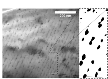
are formed in planar regular sheets as shown in Figure 1. Typically, carbonitride
sec-ond phase particles, which have been formed through the interphase precipitation phe-25
nomena are highly uniform both in terms of size and orientation [6]. The precipitates
formed are typically rich in carbon as it is significantly enriched at theγ/αinterphase
boundary [7] whereas, the the enrichment of nitrogen appears to be very limited [8],
as such for modelling purposes they shall be considered to be purely carbides in this
work. The precipitates are conventionally thought to invariably obey a single variant 30
the Baker-Nutting orientation relationship, BN OR [9]. Although, the generality of this
finding has been questioned [10]. In cases where the ferrite and the austenite into which
it grows are related by the Kurdjumov-Sachs relationship, KS OR,(111)γ k (110)α
, the particular variant will be that which makes the close packed planes of all three
phases (γ,α, and precipitate) parallel. This minimises the free energy required for nu-35
by the influence of the angular relationship between the facet upon a precipitate
em-bryo penetrating beyond both sides of theγ/αinterphase boundary and the resulting
free energy of activation for nucleation [11].
[image:4.612.126.478.175.432.2]40
Figure 1: Typical planar rows of interphase precipitates in an Fe-1.62Mn-0.19V-0.2Mo-0.19Si-0.045Cwt% alloy isothermally transformed at 973Kfor 5minsand a digitally processed binary image section showing precipitate twinning.
1.2. Modelling of Interphase Precipitation
In order to develop alloys and processes capable of exploiting the full potential
of the interphase precipitation detailed microstructural models must be developed. A
number of analytical models have been previously developed [12, 13, 14, 15, 16, 17,
18, 19, 20], which have primarily focussed upon the prediction of spacing between 45
sheets of interphase carbides. Although, this enables some guidance of the the
pro-cessing windows for hot-rolled automotive sheets a more holistic modelling approach
interphase precipitation a fundamentally different modelling approach was required, a
phase field model (PFM), which has yet to have been applied to the interphase
pre-cipitation reaction was considered. The scope of the model developed was to predict;
interphase precipitate composition, morphology and size as a function of temperature
and time. 55
The use, basic principles and potential of PFM’s for exploring a wide range of
mi-crostructural evolution and related phenomena have been reviewed in detail by Chen
[22] and Militzer [23]. A particular strength of the PFM approach is that complex
mod-els exploring morphologically complex features can be readily simulated [23] such as, 60
the precipitation ofκ-carbide in low density steels developed in our research group
[24].
2. The Present Model
Due to the wealth of experimental data from several studies on a similar alloy [25, 65
26, 27, 28], including Small angle X-Ray and Neutron Scattering (SAX and SANS)
[26] an abridged Fe-Mn-V-C quaternary composition using the values for the
respec-tive elements outlined in Table 1 has been adopted. Although the presented model
is applicable to a system with many components, we considered a quaternary system
of Fe-Mn-V-C because firstly we wanted to report the basics of our model and avoid 70
complications and secondly there was no experimental data available in the literature
reporting the interphase precipitation while all Ti, Mo,V, and other alloying elements
are present in the system. A more complex model which also includes the elastic
strain energy and binding energy terms has been also developed based on the presented
model and will be reported in our future paper. The experimental knowledge of this is 75
supplemented by the studies on the effect ofγ/αOR upon interphase precipitation of
Furuhara and co-workers [29, 30] and the 3D atom probe tomography, APT of N¨ohrer
Mukherjeeet al. demonstrated by APT, studies that the partitioning behaviour of 80
interphase precipitates greatly depends on the alloying elements [31, 32]. Here, a four
sub-lattice model was employed in order to make the interchange between Fe and Mn
atoms possible during the computation.
Table 1: Modelled composition from abridged from Refs. [26, 27] at% bal. Fe.
C Mn V
1.962 0.748 0.312
The order parameters and the concentrations for Mn, V, and C were expressed as: 85
φ1i =
(y(1)i −yi(2)−yi(3)+yi(4)) 4ci
i=M n, C, V (1a)
φ2i = (y (1)
i −y
(2)
i +y
(3)
i −y
(4)
i )
4ci
i=M n, C, V (1b)
φ3i = (y (1)
i +y
(2)
i −y
(3)
i −y
(4)
i )
4ci
i=M n, C, V (1c)
ci=
(y(1)i +yi(2)+yi(3)+yi(4))
4 i=M n, C, V (1d)
In this way, each site fractionyi(s)can be rewritten as function of order parameters
φs
i. Although the choice of eq.1a-d make the model more complicated, but this type of formalism enabled us to link Gibbs free energy to the realistic CALPHAD
thermo-dynamic database. The thermothermo-dynamics parameters used in this study are presented in
Table 2: Thermodynamic parameters for the Fe-Mn-V-C quaternary system. Parameters were taken from Refs.[33, 34, 35, 36]
BCC
GBCCF e =−22451.451 + 887.16955T−118.9T lnT−14.169×10⁻⁴T2 +7686800T−1−7.929×10⁸T−2+ 3.6×10¹⁰T−3+ 2.29603×1031T−9
GBCCM n =−70840 + 854.4548T+ 24.9T lnT−14.169×10 −4
T2
+7686800T−1−7.929×10⁸T−2+ 3.6×10¹⁰T−3+ 1.656847×1030T−9
GBCCV = 100516 + 645.5360T+ 48.77T lnT−45.149×10 −4
T2
+1.2175×10⁻⁷T3+ 7757260T−1−7.929×10⁸T−2+ 3.6×10¹⁰T−3+ 1.656847× 1030T−9
GBCCC =−17369 + 170.73T−24.3T lnT−4.723×10 −4
T2
+2562600T−1−2.643×10⁸T−2+ 1.2×10¹⁰T−3 0
LBCCF e,M n:C= 34052−23.467T
0
LBCCF e,V:C=−23674 + 0.465T
1
LBCCF e,V:C= 8283
0LBCC
F e:C =−190T
0
LBCCF e,V:C=−10000
0
LBCCV:C =−297868
FCC
GF CCF e = 32800 + 457.10556T−24.3T lnT−4.723×10⁻⁴T2 +2562600T−1−2.643×10⁸T−2+ 1.2×10¹⁰T−3
GF CCM n =−45600.41 + 498.2558T−24.3T lnT−4.723×10 −4
T2
+2562600T−1−2.643×10⁸T−2+ 1.2×10¹⁰T−3
GF CCV =−117302 + 262.57T−41.750T lnT−55.7101×10 −4
T2
+590546T−1
0LF CC
F e,M n:C= 34052−23.467T
1
LF CCF e,V:C=−7645.5−2.069T
0
LF CCF e:C=−34671
0
LF CCF e,V:C=−10000
1LF CC
M n:C=−434330LF CCV:C =−30394
Cubic (NaCl)
GCubicN aCl
F e =−27098.266 + 300.25256T−46T lnT+ 2.78854×10
31T−9
GCubicN aCl
M n =−3439.3 + 131.884T−24.5177T lnT−0.006t
2+ 69600T−1
GCubicN aCl
V = −430.43 + 135.046053T −24.134T lnT −0.003098T
2 + 1.2175×
10−7T3+ 69460T−1
0LCubicN aCl
F e,V:C =−40000
0
LCubicN aCl
F e,M n:C =−7762 + 3.865T
0LCubicN aCl
F e,M n =−7762 + 3.865T
1
LCubicN aCl
F e,M n =−259
1LCubicN aCl
M n,V =−11820
1
LCubicN aCl
F e,V =−15291−4.138T
mo-lar Gibbs energy of austenite and ferrite (Gγ,α) and that of vanadium carbideM C
precipitates which have a Cubic-NaCl crystal structure [5] (GcubicN aCl).
G(ci, y(s)i) =Gγ,α(ci) + ∆GN aCl
= [X
i
ciGγ,αi +RT
X
i
cilnci+
X
i
X
j>i
cicj m
X
n=0
(nLγ,αi:j (ci−cj)n)+
X i X j>i X k>j
cicjckLγ,αi,j:k] +
X i X j X k
yi(1)yj(2)yk(3)∆GN aCli:j:k +
RT 4 X s X i
y(is)ln(y(is))
+X s X i X j>i
y(is)yj(s)
1 X
n=0
(nLN aCli:j (y
(s)
i −y
(s)
j ) (2)
wherenLi,jandnLi,j,kare binary and ternary interaction parameters, respectively. 95
The order parameters described in Eq.1 are substituted into Eq.2 to obtain the molar
free Gibbs free energy for theα,γand interphase precipitates,cubicN aCl:
Gγ/α+cubicN aCl=X i
ciG γ/α i + X i X j>i
cicj m
X
n=0
nLγ/α
i,j (ci−cj)n
+X i X j>i X k>j
cicjckL γ/α i,j,k+ 4
X
i=M n,C,V
UF e,ic2iX
j
φii2
−4 X
i=M n,C,V
X
j>i
cicj(Ui,j−UF e,i−UF e,j)
X
k
φkiφkj
+RT 4
n
A
o
−4n B
+ 4αM n,F e,CcM ncC n C o (3) n A o = P
i=M n,C,V,M o[ci(1−φ
1
i−φ2i+φ3i)]ln[ci(1−φ1i−φ2i +φ3i)] +[1−P
i=M n,C,V,M oci(1−φ
1
i−φ2i+φ3i)]ln[ci(1−φ1i −φ2i+φ3i)] +P
i=M n,C,V,M o[ci(1−φ1i+φ
2
i−φ
3
i)]ln[ci(1−φ1i+φ
2
i−φ
3
i)]
+[1−P
i=M n,C,V,M oci(1−φ
1
i+φ2i−φ3i)]ln[ci(1−φ1i +φ2i−φ3i)] +P
i=M n,C,V,M o[ci(1 +φ
1
i−φ2i−φ3i)]ln[ci(1 +φ1i−φ2i−φ3i)] +[1−P
i=M n,C,V,M oci(1 +φ1i−φ
2
i−φ
3
i)]ln[ci(1 +φ1i −φ
2
i−φ
3
i)]
+P
i=M n,C,V,M o[ci(1 +φ
1
i+φ2i+φ3i)]ln[ci(1 +φ1i+φ2i+φ3i)] +[1−P
i=M n,C,V,M oci(1 +φ
1
i+φ2i+φ3i)]ln[ci(1 +φ1i +φ2i+φ3i)]
(4) n B o =
31LcubicNaClM n,F e c2M n((2cMn−1)P
iφi
2
M n+ 4cMnφ1M nφ2M nφ3M n) −31LcubicNaClF e,C c2C((2cC−1)P
iφi
2
C + 4cC φ1Cφ2Cφ3C) −31LcubicNaClF,V c2V((2cV−1)P
iφi
2
V + 4cV φ1Vφ2Vφ3V)
−2P
i
P
j>icicj(1LcubicNaClF e,i −1L
cubicNaCl F e,j )
P
kφkiφkj
+2cMncC cV(1LcubicNaClM n,F e −1LcubicNaClF e,C −1LcubicNaClF e,V )(P
i=M n,C,V
P
j6=i
P
k6=j6=iφ1iφ2jφ3k
+P
i=M n,C,V
P
j>i
P
kφkiφkj) −c2M ncV(1LcubicNaClM n,V + 1LcubicNaClF e,V −31LcubicNaClM n,F e )[2P
i
P
j6=i
P
k>j,k6=iφiVφjM nφkM n
+P
i(φi
2
M n+ 2φiM nφiV)] −c2M ncC(1LcubicNaClM n,C + 1LcubicNaClF e,C −31LcubicNaClM n,F e )[2P
i
P
j6=i
P
k>j,k6=iφiCφ j M nφkM n
+P
i(φi
2
M n+ 2φiM nφiC)]
+cMnc2V(1LcubicNaClM n,V + 1LcubicNaClM n,F e −31LcubicNaClF e,C )[2
P
i
P
j6=i
P
k>j,k6=iφiM nφ j VφkV
+P
i(φi
2
V + 2φiM nφiV)] −c2VcC(1LcubicNaClV,C + 1LcubicNaClF e,C −31LcubicNaClF e,V )[2P
i
P
j6=i
P
k>j,k6=iφiCφjVφkV
+P
i(φi
2
V + 2φiVφiC)]
+cMnc2C(1LcubicNaClM n,C + 1LcubicNaClM n,F e −31LcubicNaClF e,C )[2
P
i
P
j6=i
P
k>j,k6=iφiM nφ j CφkC
+P
i(φi
2
C + 2φiM nφiC)] −cV c2C(−1LV,CcubicNaCl+ 1LcubicNaClF e,V + 31LcubicNaClF e,C )[2
P
i
P
j6=i
P
k>j,k6=iφiVφ j CφkC
+P
i(φi
2
C + 2φiVφiC)]
n C o =
−c2V(
P
iφ i M nφ
j C+ 1)
P
iφ i2 V + 4c
2
V
P
iφ i M nφ
i Cφ
i2
V −(cV −1)2PiφiM nφ i C
−P
i=M n,C
P
j6=ici(3ci+ 2cj+ 2(cV −1))
P
kφ k2 i
−2cM ncC(Piφ i2 M n)(
P
iφ i2
C) + 8cM ncCPiφ i2 M nφi
2
C
+4P
i=M n,C
P
j6=icM n{φ
1
j(φ1i−φ2iφi3) +φ2j(φ2i−φ1iφ3i) +φ3j(φ3i −φ1iφ2i)}
+4P
i=M n,C
P
j6=icicV
2(φ1
i −φ2iφ3i)(φ2jφ3V +φ3jφ2V −φ1jφ1V) +2(φ2
i−φ1iφ3i)(φ1jφ3V +φ3jφ1V −φ2jφ2V) +2(φ3i−φ1iφi2)(φ1jφ2V +φ
2
jφ1V −φ
3
jφ3V) +4P
kφ k2
i φkjφkV −(
P
kφ k2 i + 1)(
P
kφ k jφkV)
+3P
i=M n,C
P
j6=ic
2
i{−(
P
kφ k2
i + 1)
P
kφ k iφ
k j+ 2
P kφ k3 i φ k j
+2(φ1jφ2iφ3i+φ1iφj2φ3i+φ1iφ2iφ3j)}+ 2
P
i
P
j>i
P
k6=j,k6=i(φ i M nφ
j C+φ
j M nφ
i C
−φk
M n−φkC)(−c2V φiVφ j
V −cVφkφVk +c2VφkV)
−8cM ncC{Pi
P
j6=i
P
k>j,k6=i(φ i M n−φ
j M nφ
k M n)(φ
i C−φ
j Cφ
k C)}
+6(c2M nφ
1
M nφ
2
M nφ
3
M n+c
2 Cφ 1 Cφ 2 Cφ 3 C) (6)
The total stress-free chemical free energy of the system in the Fe-Mn-C-V system
can be expressed as [37]: 100 F≡ Z V ( 1 Vm
Gα,γor CubicN aCl+α
2 3 X
i=M n,C,V
(∇ci)2
+ [β 2
3 X
i=M n,C,V
(∇φji)2])dV (7)
Where,Vmis the molar volume which is considered to be constant equal to7.3∗
10−6m3/mole.αandβare the gradient energy coefficients for the compositions and
order parameters, respectively. The temporal evolution of the elemental concentrations
Cahn-Hilliard diffusion equations and time-dependant Ginzburg-Landau equations: 105
∂ci
∂t =
X
j
∇.( ˜Mij∇
δF δcj
), i=M n, C, V, j=M n, C, V (8)
∂φji
∂t =−L
δF
δφji, i=M n, C, V, j= 1,2,3 (9)
where,M˜ij andLare the diffusion mobility and the structural relaxation,
respec-tively. The diffusion mobility,M˜ij, was related by the atomic mobilities of Mn, V, C
and Fe using the following equation[38]:
˜
Mij =
X
n
(δin−ci)(δjn−cj)cnMnF e (10)
where,δinandδjnrepresent the Kronecker delta. diffusivity of Mn, V, and C in
αandγwere taken to beMM nα,F e= 7.03881e−18,MM nγ,F e = 7.23763e−20,MCα,F e = 110
6.14251e−11,MCγ,F e = 3.67803e−13,MVα,F e= 1.0552e−17,MVγ,F e= 1.55038e−19,
respectively. The parameterLwas determined byM˜C=La20/16[39], wherea0is the
lattice parameter of the matrix. The binding energy of Mn to the interphase boundary
was assumed to be 9.9 kJ/mol [40]. αM n,F e,C was assumed to be 31270Jm2/mol
[34]. The value of the gradient coefficientβ was3.8×10−16J/m. This value was 115
observed by atom probe analyses [31] for multicomponent systems and gives the
inter-phase interfacial diffuse chemical profile equating to∼3 nm. The values for both
coefficientsαandβ was considered to be the same for all phases involved for the
sake of simplicity and in order to develop on single free energy function to describe the
evolution. At the nucleation stage, small cells with a side of 1 nm were seeded to NaCl-120
type interphase precipitates after uniform random value was generated for nucleation
sites at the inter-phase. For multi-particle simulations, the number of nucleus in the
field was determined according to experimental observations reported in Ref.[31, 34].
These calculations are currently being done in our research group and will be presented
in our future papers. The grid size was set to 0.5 nm with a total number of grids equal 125
to 300×300×300. A Semi-Implicit-Fourier-Spectral-Method [41] was employed for
3. Experimental Validation and Discussion
A three dimensional simulation for the microstructural development of an
Fe-Mn-V-C quaternary system isothermally transformed at 973Kwas performed through di-130
rectly linking free energy calculations to the CALPHAD method. The simulation for a
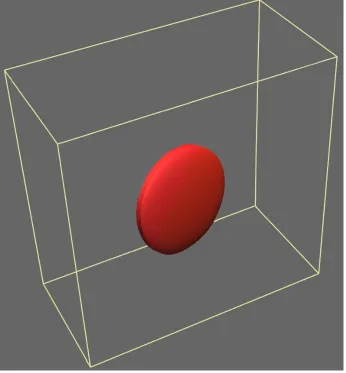
single interphase precipitate growing on a stationaryγ/αinterphase boundary shows
that the particle has a disk-like shape (Fig.2) similar to the abutted spherical caps
pre-dicted morphology for grain boundary precipites considered by Clemm and Fisher [42].
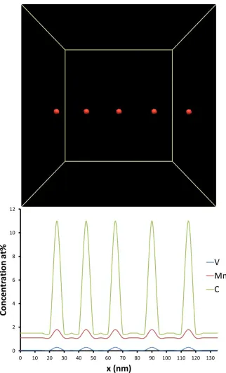
The predictions of which are shown in Figures 3, 4 and 5. The cross-sectional com-135
positional evolution of the precipitates growing along theγ/αinterphase boundary are
also shown in each figure accompanying each image of the growing precipitate after
a given number of modelled time steps. After the formation of nuclei, the particles
were found to be supersaturated with C of 11.1 at%, as shown in Fig.3. The degree
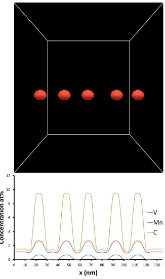
of supersaturation then continuously decreased as the precipitates grew, as is evident 140
from Fig.4 until it reached the equilibrium value of 8 at%. The partitioning of Mn and
V atoms into the precipitates, however, was not as rapid as that of C due to the smaller
Figure 2: Oblate spheroid morphology of a single interphase precipitate after 6000∆t steps.
The modelled interphase precipitate composition, and oblate spheroid morphology 145
in Figure 4 is in strong accordance with the dual SAX and SANS scattering
interpreta-tions of Obaet al.[26]. At 973KObaet al.[26] measured an average diameter of the
precipitates as 23nmthis is very similar to our model prediction after 2000∆tsteps.
However, some discrepancy is found if the model predictions are compared with the
re-cent 3D APT studies of Mukherjeeet al.[31, 32] where, a precursor nano-cluster to the 150
interphase precipitates are observed and are found to significantly enriched in Ti and
a significant solute drag effect upon theγ/αinterphase boundary and are significantly
enriched locally at the interphase boundary. Mo and Ti were not considered in this
study. In respect to V however, the binding energy with theγ/αinterphase boundary 155
is thought to be far less significant in comparison to that of Ti and Mo [43]. V
segre-gation and consequentially supersaturation in the precipitates therefore, would not be
expected to be large at a movingγ/αinterphase boundary [44]. This was
experimen-tally observed using 3D APT in a V micro-alloyed steel by N¨ohreret al.[8]. The model
is found to predict predict the observed enrichment of Mn in the interphase precipitates 160
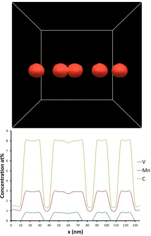
com-Figure 5: Morphology, size of growing interphase precipitates after 6000∆tsteps and cross-sectional com-position profile of Mn, V and C at theγ/αinterphase boundary in respect tox.
[image:17.612.159.472.121.608.2]in-terphase interface does not always obey the KS OR. The studies by Lawet al.[45],
Okamotoet al.[10] and, Yenet al. [46] and recently the studies of Furuhara and
co-workers[28, 29, 30] have elucidated the role ofγ/αOR upon interphase precipitation 165
and shown that interphase precipitation is not solely related to the KS interphase
bound-ary. In particular, Zhanget al.[29, 30] have shown that interphase precipitate density
increases with increasing misorientation from an ideal KS interphase boundary.
Recently, it has been observed that in some circumstances, in regions where planar 170
interphase precipitation is exhibited the precipitates appear to exist in pairs, where the
oblate spheroid precipitates appear to join at the tips [47]. The reason for this
phe-nomena has yet to be resolved. However, it can be observed when in the 3D APT of
Zhanget al.[29, 30], where precipitates pairing at the tips can be seen at relatively low
transformation temperatures and relatively small values ofγ/α∆θ, although not equal 175
to 0 missorietation from the ideal KS OR.
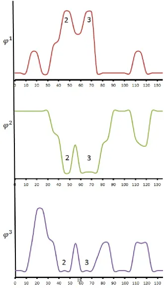
As shown in fig.5, two precipitates paired together at final stages of the
simula-tion. The pairing occurred in order to decrease their interfacial energies. To elucidate
the pairing between these two particular precipitates, the order parameter of Mn after 180
6000∆tsteps is presented in Fig.6. These two precipitates of interest are indicated by
numbers 2 and 3. As shown in this figure, the domain of precipitate 2 was the same
as that of 3 while those of other precipitates were different. This phenomenon is very
similar to the precipitation behaviour in super-alloys and light weight steels, where
4. Conclusions
A multi-component phase field model was developed for the simulation of
inter-phase precipitation of carbide precipitates in steels. The model was directly coupled
with thermodynamic data from the CALPHAD method using a four-sub-lattice model.
Interphase carbide precipitation at theγ/αinterface was simulated. The developed 190
model has been used to elucidate the mechanisms for interphase precipitate growth
with particular reference to vanadium carbide precipitation in medium-carbon
micro-alloyed steels isothermally transformed at973K.
The model is found to be able to accurately predict: 195
1. Interphase precipitate composition, is in accordance with the dual SAX and
SANS study of Obaet al. [26]. Our model does predict the observed
enrich-ment of Mn.
2. Morphologythe model is found to accurately predict oblate spheroid precipitates
and their size. 200
3. The phenomena tip-to-tip pairing of interphase precipitates inγ/αinterphase
boundaries found to be attributable to the minimisation of interfacial energy.
5. Acknowledgement
Authors are thankful for financial support from the EPSRC grant EP/L018632/1
“Micro-structuring micro-alloyed steels via non-metallic precipitate formation” and 205
financial assistance from the WMG Centre High Value Manufacturing Catapult are
gratefully acknowledged.
References
Mater-[2] R. A. Rijkenberg, A. Blowey, P. Bellina, C. Wooffindin, Advanced High
Stretch-Flange Formability Steels for Chassis & Suspension Applications 3 . Product
concept : tensile properties and microstructure (2014).
[3] Y. Funakawa, T. Shiozaki, K. Tomita, T. Yamamoto, E. Maeda,
Devel-opment of High Strength Hot-rolled Sheet Steel Consisting of Ferrite and 215
Nanometer-sized Carbides, ISIJ Int. 44 (11) (2004) 1945–1951. doi:10.
2355/isijinternational.44.1945.
[4] R. W. K. Honeycombe, Transformation from austenite in alloy steels, Metall.
Trans. A 7 (July) (1976) 915–936.doi:10.1007/BF02644057.
[5] R. Lagneborg, B. Hutchinson, T. Siwecki, S. Zajac, The Role of Vanadium in 220
Microalloyed Steels, 2nd Edition, no. June, Swerea KIMAB, Stockholm, 2014.
[6] H.-W. Yen, C.-Y. Huang, J.-R. Yang, Characterization of interphase-precipitated
nanometer-sized carbides in a Ti-Mo-bearing steel, Scr. Mater. 61 (6) (2009) 616–
619. doi:10.1016/j.scriptamat.2009.05.036.
URLhttp://dx.doi.org/10.1016/j.scriptamat.2009.05.036
225
[7] A. T. Davenport, R. Honeycombe, Precipitation of carbides at y-a boundaries in
alloy steels, Proc. R. Soc. London A 322 (1549) (1971) 191–205.
[8] M. N¨ohrer, S. Zamberger, S. Primig, H. Leitner, Atom probe study of vanadium
interphase precipitates and randomly distributed vanadium precipitates in ferrite,
Micron 54-55 (2013) 57–64.doi:10.1016/j.micron.2013.08.008. 230
URLhttp://dx.doi.org/10.1016/j.micron.2013.08.008
[9] R. M. Smith, D. P. Dunne, Structural aspects of alloy carbonitride precipitation in
microalloyed steels, Mater. Forum 11 (1988) 166–181.
[10] R. Okamoto, A. Borgenstam, J. Agren,˚ Interphase precipitation in
niobium-microalloyed steels, Acta Mater. 58 (14) (2010) 4783–4790. 235
doi:10.1016/j.actamat.2010.05.014.
URL http://linkinghub.elsevier.com/retrieve/pii/
[11] J. K. Lee, H. I. Aaronson, Influence of faceting upon the equilibrium shape of
nuclei at grain boundaries-II. Three-dimensions, Acta Metall. 23 (7) (1975) 809– 240
820.
[12] H. K. D. H. Bhadeshia, Diffusional Transformations: A theory for the formation
of superledges, Phys. Status Solidi a-Applied Res. 69 (2) (1982) 745–750.
[13] J. A. Todd, P. Li, S. M. Copley, A new model for precipitation at moving
inter-phase boundaries, Metall. Trans. A 19 (September) (1988) 2133–2138. doi:
245
10.1007/BF02645038.
[14] W. J. Liu, Computer simulation of VC Precipitation at Movingγ/αInterfaces,
Metall. Trans. A 24 (10) (1993) 2195–2207.doi:10.1007/BF02648594.
URL http://www.springerlink.com/index/10.1007/
BF02648594
250
[15] P. R. Rios, Morphology of interphase precipitation in microalloyed steels, J.
Mater. Sci. Lett. 10 (1991) 981–983.doi:10.1007/BF00722153.
[16] P. R. Rios, A model for interphase precipitation in stoichiometrically
bal-anced vanadium steels, J. Mater. Sci. 30 (1995) 1872–1878. doi:10.1007/
BF00351624. 255
[17] R. Lagneborg, S. Zajac, A model for interphase precipitation in V-microalloyed
structural steels, Metall. Mater. Trans. A 31 (001) (2001) 1–12.
URL http://link.springer.com/article/10.1007/
s11661-001-0249-9
[18] M.-Y. Chen, M. Goun´e, M. Militzer, Y. Br´echet, J.-R. Yang, Su-260
perledge Model for Interphase Precipitation During Austenite-to-Ferrite
Transformation, Metall. Mater. Trans. A 45 (12) (2014) 5351–5361.
doi:10.1007/s11661-014-2486-8.
[19] M.-Y. Chen, M. Goun´e, M. Verdier, Y. Br´echet, J.-R. Yang, Interphase
precipita-tion in vanadium-alloyed steels: Strengthening contribuprecipita-tion and morphological
variability with austenite to ferrite transformation, Acta Mater. 64 (2014) 78–92.
doi:10.1016/j.actamat.2013.11.025.
URL http://linkinghub.elsevier.com/retrieve/pii/
270
S1359645413008756
[20] S. Clark, V. Janik, Y. Lan, S. Sridhar, Interphase Precipitation An Interfacial
Segregation Model, ISIJ Int. 57 (3).
[21] H. I. Aaronson, M. R. Plichta, G. W. Franti, K. C. Russell, Precipitation at
in-terphase boundaries, Metall. Trans. A 9 (3) (1978) 363–371. doi:10.1007/
275
BF02646386.
[22] L.-Q. Chen, Phase -Field Models for Microstructure Evolution, Annu. Rev.
Mater. Res. 32 (1) (2002) 113–140. doi:10.1146/annurev.matsci.
32.112001.132041.
URL http://www.annualreviews.org/doi/abs/10.1146/
280
annurev.matsci.32.112001.132041
[23] M. Militzer, Phase field modeling of microstructure evolution in steels, Curr.
Opin. Solid State Mater. Sci. 15 (3) (2011) 106–115. doi:10.1016/j.
cossms.2010.10.001.
URLhttp://dx.doi.org/10.1016/j.cossms.2010.10.001
285
[24] A. Rahnama, R. Dashwood, S. Sridhar, A phase-field method coupled with
CALPHAD for the simulation of ordered ordered k-cabide precipitates in both
disorered gamman and alpha phases in low density steel, Comput. Mater. Sci.
126 (2017) 152–159.doi:10.1016/j.commatsci.2016.09.015.
URL http://linkinghub.elsevier.com/retrieve/pii/
290
S0927025616304566
[25] G. Miyamoto, R. Hori, B. Poorganji, T. Furuhara, Interphase precipitation of
(2011) 1733–1739.doi:10.2355/isijinternational.51.1733.
URL http://www.scopus.com/inward/record.url?
295
eid=2-s2.0-82455184379{&}partnerID=40{&}md5=
58d1e60f8a2651d957d6c5fac7b56dbe
[26] Y. Oba, S. Koppoju, M. Ohnuma, T. Murakami, H. Hatano, K. Sasakawa,
A. Kitahara, J. Suzuki, Quantitative Analysis of Precipitate in
Vanadium-microalloyed Medium Carbon Steels Using Small-angle X-ray and Neutron 300
Scattering Methods, ISIJ Int. 51 (11) (2011) 1852–1858. doi:10.2355/
isijinternational.51.1852.
[27] T. Murakami, H. Hatano, G. Miyamoto, T. Furuhara, Effects of Ferrite Growth
Rate on Interphase Boundary Precipitation in V Microalloyed Steels, ISIJ Int.
52 (4) (2012) 616–625. doi:10.2355/isijinternational.52.616. 305
URL http://joi.jlc.jst.go.jp/JST.JSTAGE/
isijinternational/52.616?from=CrossRef
[28] G. Miyamoto, R. Hori, B. Poorganji, T. Furuhara, Crystallographic Analysis
of Proeutectoid Ferrite/Austenite Interface and Interphase Precipitation of
Vanadium Carbide in Medium-Carbon Steel, Metall. Mater. Trans. A 44 (8) 310
(2013) 3436–3443.doi:10.1007/s11661-013-1702-2.
URL http://link.springer.com/10.1007/
s11661-013-1702-2
[29] Y.-J. Zhang, G. Miyamoto, K. Shinbo, T. Furuhara, Effects ofα/γ orientation
relationship on VC interphase precipitation in low-carbon steels, Scr. Mater. 315
69 (1) (2013) 17–20.doi:10.1016/j.scriptamat.2013.03.020.
URL http://linkinghub.elsevier.com/retrieve/pii/
S1359646213001814
[30] Y. Zhang, G. Miyamoto, K. Shinbo, T. Furuhara, T. Ohmura, T. Suzuki,
precipita-doi:10.1016/j.actamat.2014.10.049.
URLhttp://dx.doi.org/10.1016/j.actamat.2014.10.049
[31] S. Mukherjee, I. B. Timokhina, C. Zhu, S. P. Ringer, P. D. Hodgson,
Three-dimensional atom probe microscopy study of interphase precipitation and 325
nanoclusters in thermomechanically treated titanium-molybdenum steels, Acta
Mater. 61 (7) (2013) 2521–2530. doi:10.1016/j.actamat.2013.01.
028.
URLhttp://dx.doi.org/10.1016/j.actamat.2013.01.028
[32] S. Mukherjee, I. B. Timokhina, C. Zhu, S. P. Ringer, P. D. Hodgson, Clustering 330
and precipitation processes in a ferritic titanium-molybdenum microalloyed steel,
J. Alloys Compd. 690 (2017) 621–632. doi:10.1016/j.jallcom.2016.
08.146.
URLhttp://dx.doi.org/10.1016/j.jallcom.2016.08.146
[33] P. Gustafson, Thermodynamic evaluation of the Fe-C System, Scand. J. Metall. 335
14 (5) (1985) 259–267.
[34] W. Huang, Thermodynamic properties of the Fe-Mn-VC system, Metall. Trans.
A 22 (September) (1991) 1911–1920.
URL http://link.springer.com/article/10.1007/
BF02669859
340
[35] K. Frisk, Thermodynamic modelling of multicomponent cubic Nb, Ti and V
car-bides/carbonitrides, Calphad Comput. Coupling Phase Diagrams Thermochem.
32 (2) (2008) 326–337. doi:10.1016/j.calphad.2007.11.007.
[36] V. Raghavan, C-Fe-N-Nb-V (Carbon-Iron-Nitrogen-Niobium-Vanadium),
J. Phase Equilibria Diffus. 33 (5) (2012) 1–3. doi:10.1007/
345
s11669-012-0105-1.
[37] J. W. Cahn, J. Hilliard, Free Energy of a Nonuniform System. I. Interfacial Free
10.1063/1.1744102.
URLhttp://dx.doi.org/10.1063/1.1744102
350
[38] T. Kitashima, T. Yokokawa, A. C. Yeh, H. Harada, Analysis of element-content
effects on equilibrium segregation at gamma/gamma-prime interface in Ni-base
superalloys using the cluster variation method, Intermetallics 16 (6) (2008) 779–
784. doi:10.1016/j.intermet.2008.02.015.
[39] R. Poduri, L.-Q. Chen, Computer simulation of atomic ordering and compo-355
sitional clustering in the pseudobinary Ni3AlNi3V system, Acta Mater. 46 (5)
(1998) 1719–1729.doi:10.1016/S1359-6454(97)00335-2.
[40] H. Chen, S. van der Zwaag, A general mixed-mode model for the
austenite-to-ferrite transformation kinetics in FeCM alloys, Acta Mater. 72 (2014) 1–12.
doi:10.1016/j.actamat.2014.03.034.
360
URL http://www.sciencedirect.com/science/article/pii/
S1359645414001815
[41] L.-Q. Chen, J. Shen, Applications of semi-implicit Fourier-spectral method
to phase field equations, Comput. Phys. Commun. 108 (2-3) (1998) 147–158.
doi:10.1016/S0010-4655(97)00115-X.
365
URL http://www.sciencedirect.com/science/article/pii/
S001046559700115X
[42] P. Clemm, J. Fisher, The influence of grain boundaries on the nucleation of
sec-ondary phases, Acta Metall. 3 (1955) 70–73.
[43] H. Jin, I. Elfimov, M. Militzer, Study of the interaction of solutes with Σ5 370
(013) tilt grain boundaries in iron using density-functional theory, J. Appl. Phys.
115 (9). doi:10.1063/1.4867400.
[44] G. R. Purdy, Y. J. M. Br´echet, A solute drag treatment of the effects of
[45] N. C. Law, S. A. Parsons, P. R. Howell, D. V. Edmonds, Crystallography of
carbide precipitation at transformation interfaces during austenite
decomposi-tion in a low-alloy steel, Mater. Sci. Technol. 3 (8) (1987) 642–648. doi:
10.1179/026708387790329559.
380
[46] H.-W. Yen, P.-Y. Chen, C.-Y. Huang, J.-R. Yang, Interphase
pre-cipitation of nanometer-sized carbides in a
titaniummolybdenum-bearing low-carbon steel, Acta Mater. 59 (16) (2011) 6264–6274.
doi:10.1016/j.actamat.2011.06.037.
URL http://linkinghub.elsevier.com/retrieve/pii/
385
S1359645411004514
[47] A. Chamisa, Development of Ultra High Strength Steels for Reduced Carbon
Emissions in Automotive Vehicles, Ph.D. thesis, University of Sheffield (2014).
![Table 2: Thermodynamic parameters for the Fe-Mn-V-C quaternary system. Parameters were taken fromRefs.[33, 34, 35, 36]](https://thumb-us.123doks.com/thumbv2/123dok_us/9443800.451630/7.612.134.479.125.622/table-thermodynamic-parameters-fe-quaternary-parameters-taken-fromrefs.webp)