© 2019, IRJET | Impact Factor value: 7.211 | ISO 9001:2008 Certified Journal | Page 3605
Design, Development and Manufacturing of Braking System for ATV
Krishna Chavan
1, Chandani Kumari
2, Pratiksha Pawar
3, Akshay Bawankar
4,
U. C. Agashe
51,2,3,4
B.E. student, Dr. D. Y. Patil Institute of Technology, Pimpri Pune-411018 India
5
Assistance Professor, Dr. D. Y. Patil Institute of Technology, Pimpri Pune-411018 India
---***---Abstract -
Various factors are so important to Design,Development and Manufacturing of Braking System for All Terrain Vehicle. The performance of designed brake system was dependent on some parameter such as weight distribution, deceleration, pedal effort, pressure generation in master cylinder, wheels lock sequence etc. Finally, all theoretical results were validated with experimental results. The master cylinder being the Heart of braking system and the whole system built considering its strength. The developed design of Inboard Braking system results in reduced size of wheel assembly, reduced weight and effective braking.
Key Words:Pedal, Master Cylinder, Brake lines, Caliper,
Brake Pads and Rotor.
1. INTRODUCTION
The braking system depends upon the frictional force to stop, to control or to prevent the motion [1]. An efficient
braking system is required to create enough deceleration to stop the car as quickly as the driver wishes, without exceeding the driver comfort level with regard to the pedal effort and to effectively dissipate the heat generated due to friction. Brakes used can be of Drum or Disc type. Usually Disc brakes are used at all four wheels as it can provide efficient braking and bear more loads in the scenario of weight transfer during the deceleration.
Modern cars mostly use hydraulic brakes. Hydraulic brakes use an enclosed fluid to transmit the pedal force to stop the vehicle. Force applied by the driver is multiplied in the braking system by a principle called Pascal’s law. The law states: “a pressure change occurring anywhere in a confined incompressible fluid is transmitted throughout the fluid such that the same change occurs everywhere.”[2] Friction
between the rotating disc and stationary pads are used as a tool to stop the vehicle within a considerable distance. The component used in hydraulic braking system are designed and manufactured according to the requirement of ATV.
2. OBJECTIVES OF BRAKING SYSTEM FOR ATV
To lock all four wheels at a same time
To ensure safety of the driver completely
To improve braking efficiency
To reduce accidents
To reduce the unsprung mass of the vehicle
3. LITRETURE SURVEY
[1] Manjunath TV and Dr. Suresh PM did analysis on the thermo mechanical behavior of the dry contact of the brake disc during the braking phase. The coupled thermal structural analysis was used to determine the deformation and the von-mises stress established in the disc for the both solid and ventilated disc with two different materials to enhance the performance of the rotor disc. A comparison between analytical and results obtained from FEM was done and all the values obtained from the analysis was less than their allowable values. Hence the best suitable design, material and the rotor disc was suggested on the performance, strength and rigidity criteria.
[2] Karthick C and Kumaresan G did research on thermal analysis and enhancement of disc brakes. The research is about the fabrication of disc brake and an attempt has been made ti investigate the material selection, manufacturing process and testing. Thus the results provide better understanding on the fabrication and testing behavior of disc brakes and assist the automotive industry in developing optimum and effective disc brake rotor.
[3] Swapnil R. Abhang, and D.P Bhaskar determines, instead of having air bag, good suspension systems, good handling and safe cornering, there is one most critical system in the vehicle which is brake systems. Without brake system in the vehicle will put a passenger in unsafe position. Therefore, it is must for all vehicles to have proper brake system. In this paper carbon ceramic matrix disc brake material use for calculating normal force, shear force and piston force. Also calculating the braking distance of disc brake. The standard disc brake two wheelers model using in Ansys and done the Thermal analysis and Modal analysis also calculate the deflection and Heat flux, Temperature of disc brake model.
[4] Thiagu S.M, Varun.N, Lokeshwaran.R The analysis on the thermo mechanical behavior of the dry contact of the brake disc during the braking phase. The coupled thermal structural analysis was used to determine the deformation and the von-mises stress established in the disc for the both solid and ventilated disc with two different materials to enhance the performance of the rotor disc.
© 2019, IRJET | Impact Factor value: 7.211 | ISO 9001:2008 Certified Journal | Page 3606
on the fabrication and testing behavior of disc brakes andassist the automotive industry in developing optimum and effective disc brake rotor.
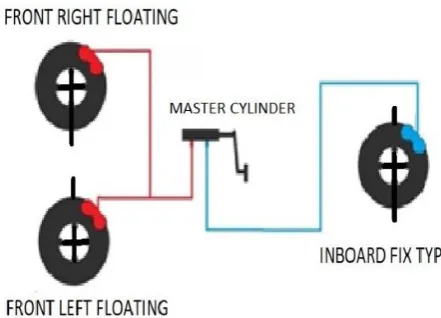
[image:2.595.54.275.176.335.2]4. LAYOUT OF BRAKING CIRCUIT
Figure 1. Layout of braking system
Master cylinder with required dimensions of piston is designed to generate appropriate pressure in the brake circuit. Pedal ratio is the mechanical advantage provided by the pedal.Pedal with optimum pedal ratio is used to multiply the force applied by the driver and transmit it to the master cylinder. The braking system is separated in two different independent circuits so that leakage or failure at any point in the system can’t affect the whole braking system. Pressure generated in master cylinder is carried to the caliper through the fluid lines. Most brake fluids used today are glycol-ether based considering its characteristics like viscosity, boiling point, corrosion, compressibility. Pistons in caliper push the brake pads against the rotor to apply frictional force to decelerate and ultimately stop the vehicle by converting kinetic energy into heat energy.
5. CALCULATIONS
5.1 Overview of design
The braking system uses a front/ rear split braking circuit. Two master cylinders having a bore diameter of 15.875mm are used. Two fixed single piston calipers on front wheels and one floating dual piston caliper on the rear inboard disc is used. Bore diameter for front and rear caliper is 34mm rear and 32mm respectively. The brake calipers are connected to the master cylinder with the steel braided flexible brake lines which ensures that there is no leakage of the brake fluid.
Material for the rotor: SS410
Material for the brake pedal: Al 6061-T6 Material for Brake Caliper: Al 7075-T6
It was thought critical for brake system to be designed such that the front and rear brakes lock up at the same rates. This Would maximize deceleration and reduce the stopping distance.
Braking Force required to stop the vehicle Speed =16.16m/sec
S.D.(stopping distance) =4.5m T.M.C. bore Diameter=15.875mm Acceleration =5.08m/s2
Braking Force = m*a =200*5.08 =1016N 5.2 Weight distribution Here,
Ff= Braking Force on Front Wheel Fr= Braking Force on Rear Wheel Tb=Braking Torque
r= tyre radius FRONT: -
Splitting Braking force according to weight distribution Ff =1016 N
For single tyre, Ff=508 N Tb= r*Ff
Tb =0.2921*508 =148.446 Nm REAR: -
Fr =361.587 N Tb =0.2921*361.587 =105.619 Nm
5.3 Caliper Bore Diameter Here,
Fcp = Force generated by caliper piston Fcf = Clamping Force
Acp= Area of caliper piston Tr = Torque at rear axle Tf = Torque at Front axle Reff = Effective radius off rotor
µ = Coefficient of friction between Rotor and Brake pad
© 2019, IRJET | Impact Factor value: 7.211 | ISO 9001:2008 Certified Journal | Page 3607
Fcf = 2*µ*Fcp=2*0.38*7750.535 =5890.406 N Tr = Fcf * Reff
=5890.406 *0.0735 =432.944 Nm REAR
Rear =32 mm Fcp = P *Acp =5934.003 N Fcf =2*µ*Fcp =4509.84 N Tf =308.924 Nm
5.4 Deceleration and stopping distance Deceleration is calculated by following formula W = x.a.m.g
Where, W =weight transfer =584.515 N a = deceleration (in form of g)
M =mass of vehicle = 200 kg g =9.81 m/s2
a = 6.89 m/s2
average acceleration of vehical aavg = 3.108 m/s2
Stopping distance is calculated by following formula S= 4.5 m
3.7 THERMAL CALCULATION
Maximum Speed = 60 km/hr = 16.66 m/s2 Kinetic energy =1/2 *m*v2
=1/2 *200*16.662 = 27755.56 J
Total kinetic energy =Heat generated = 27755.56 J Area of Rubbing Surface (Front) = π/4*(Do2 –Di2) = π/4*(0.162 –0.1142) = 9.899*10-3 m2
Skid distance for 60 Kmph = 5.767m Stopping time = d/ν
= 4.56/16.66 = 0.27 sec
Total Stopping Time = 0.27 + Reaction time = 0.27 +1.5
= 1.77 sec
Heat flux = (heat generated*rubbing distance)/t = 1.584*106 W/m2
Tmax =148.643 °C (Front) Rear rotor diameter = 170 mm =0.17 m
= 1.476*106 W/m2
Tmax (Rear)= 145.5539
6. DESIGN AND ANALYSIS OF COMPONENT
Brake Disc, Caliper, Brake master cylinder and Pedal were designed in CATIA V5R21.
The analysis of disc and heat flux distribution of Disc, Deformation in caliper and stress induced in pedal was performed in Ansys 19.1.
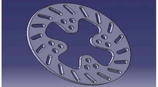
6.1 Design and analysis of brake disc
Mesh size – 2mm
[image:3.595.306.562.591.732.2]Heat Flux (1.476W/mm2) & Radiation (To Ambient)
© 2019, IRJET | Impact Factor value: 7.211 | ISO 9001:2008 Certified Journal | Page 3608
Figure 2. Temperature Analysis [image:4.595.306.563.99.306.2] [image:4.595.37.285.330.536.2]Figure 3. CAD Model of Self-Manufactured Caliper
[image:4.595.311.560.331.538.2]Figure 5. FEA Analysis of Caliper
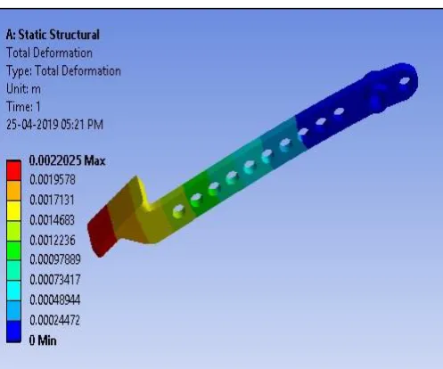
Figure 5. CAD Model of Brake Pedal
Figure 6. FEA Analysis of Brake Pedal
7. CONCLUSION
The brake assembly is one of the most important parts of any automotive system. The above designed brake assembly is used in BAJA ATV during BAJA SAE India 2019 and BAJA SAE International 2019. During the event all four wheels at lock at the same time and brake test was cleared in the first attempt itself.
ACKNOWLEDGEMENT
[image:4.595.38.288.560.746.2]© 2019, IRJET | Impact Factor value: 7.211 | ISO 9001:2008 Certified Journal | Page 3609
REFERENCES
[1] S. Mishra and S. Jandhu, “Balance bar design and motion analysis of pushrod”. International Journal of Mechanical Engineering and Robotics Research. Vol.3, No.3, July 2014. [2] Aman Sharma1, Prakhar Amrute2, Suryakant Singh Thakur3, Jatin Shrivastav4 “DESIGN, ANALYSIS AND FABRICATION OF BRAKING SYSTEM WITH REAR INBOARD BRAKES IN BAJA ATV” International Research Journal of Engineering and Technology Volume.05, Issue.05, May 2018.
[3] Theory of ground vehicles, Third edition by J.Y
Wong
[4] Brake design and safety by Rudolf Limpert
[5] Aluminium composite for brake disc, Edition one
by V. Saravanan
[6] Alternate material in automobile brake disc, by
Telang A.K.
[7] Brake Handbook by Rick Baile
[8] University of Cincinnati SAE Baja Race Team by
Mark Schmidt
[9] Bearcats Baja Braking System
By
Richard
T. Best
http://www.iaeng.org/publication/WCE2010/WCE20
10_pp2322 -2326.pdf
https://en.wikipedia.org/wiki/Inboard_brake
https://racemagazine.com.au/topic/inboard-vs-outboard-rear-brakes
https://www.carthrottle.com
https://www.f1technical.net
BIOGRAPHIES
KRISHNA CHAVAN
CHANDANI KUMARI
PRATIKSHS PAWAR
AKSHAY BAWANKAE