DOI: 10.4236/oalib.1104719 Jan. 10, 2019 1 Open Access Library Journal
School of Electronic & Information, Yangtze University, Jingzhou, China
Abstract
This paper mainly uses the MATLAB software to design IIR digital filter with the amplitude frequency characteristic method and zero-pole method, and then analyzes the effect of coefficient quantization and quantization effects in IIR digital filter arithmetic. It is that we can use the software to draw some pictures. These pictures can show coefficient system function of IIR digital filter with a certain length to quantify the zero pole after the system distribu-tion, frequency response, after quantizing the coefficients under the direct, parallel and cascade structures, as well as the limit cycle oscillation and the overflow oscillation of fixed-point operation in the quantization effect of op-eration are drawn.
Subject Areas
Computer Engineering, Multimedia/Signal Processing
Keywords
Infinite-Impulse Response (IIR), Filter Design, Word Length, Error, Graphical User Interface (GUI)
1. Introduction
In theoretical analysis of discrete-time systems, we generally assume that signal values and system coefficients are represented in the real-number system. How-ever, with analog discrete-time systems, the limited precision of the components of a circuit makes it difficult to realize coefficients exactly. Similarly, when im-plementing digital signal processing systems, we must represent signals and coefficients in some digital number that must always be of finite precision [1]. Most general-purpose digital computers, DSP chips, or special-purpose hard-ware use a binary system. The coefficients of digital filters designed by theory
How to cite this paper: Nandintsetseg, G. and Sun, X.-E. (2019) The Finite-Precision Numerical Effects Analysis of Infinite Impulse Response. Open Access Library Journal, 5: e4719.
https://doi.org/10.4236/oalib.1104719
Received: June 12, 2018 Accepted: January 7, 2019 Published: January 10, 2019
Copyright © 2019 by authors and Open Access Library Inc.
This work is licensed under the Creative Commons Attribution International License (CC BY 4.0).
DOI: 10.4236/oalib.1104719 2 Open Access Library Journal
method are infinite in precision. And all filter coefficients must be in binary form of limited length stored in memory, so we must quantify the ideal value. It will bring error between the actual coefficient and original coefficient, and cause the deviation of zero pole position, thus affecting the performance of the filter. If the coefficients quantization error is large, pole of IIR digital filter may be removed from the unit circle, making the system unstable and not available. Effect of digital filter coefficient quantization is related to word length, as well as the filter structure
[2][3]. The analysis of sensitivity of filter pole can reflect the influence of coeffi-cient quantization having on zero and pole position in different filter structures.
In addition, calculation will also bring error. The finite word length effect in the computation process has a complex relationship with the system used (fixed-point, floating-point system), the code system (the original code, com-plement) and quantization (rounding, truncating) [3].
2. MATLAB Implementation the Effects of Quantization on
the Performance in IIR Filters
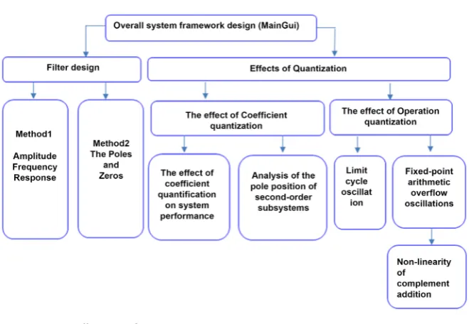
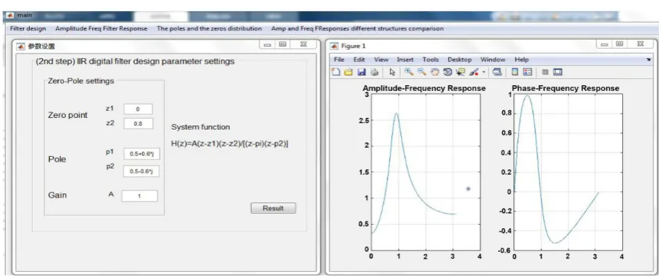
Based on the analysis of the effects of learning quantization on the performance of IIR filters, we designed and implemented a MATLAB-based quantization ef-fect analysis system for the performance of IIR digital filters. Using this system, the IIR system can be analyzed different word length conditions as shown Figure 1.
2.1. Overall System Framework Design in Matlab
The quantization effect of IIR digital filters [4][5] is mainly manifested in two aspects:
1) The Operational quantization effect.
The basic mathematical operation for implementing a digital filter is a con-stant that multiplies some number or two numbers. Where there is a multiplica-tion of coefficients, there is a source of quantizamultiplica-tion error noise, which can all cause errors in the output of the coefficients.
2) The Coefficient quantization effect.
The effect of coefficient quantization on the filter is related to the word length, and it is also closely related to the structure of the filter. Analysis of the zero-pole sensitivity can reflect the effect of coefficient quantification on the position of the zero pole in the case of different structures. After analysis, it can be con-cluded that the deviation of the pole formed by the sensitivity of the pole posi-tion cannot directly obtain the deviaposi-tion of the frequency response. Especially in the high-order case, there are many coefficients, and their quantization errors are more random. Therefore, statistical analysis method is used to consider the coefficient quantization error as a random variable, so as to analyze the devia-tion of the estimated frequency response of the filter.
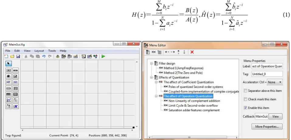
2.2. Matlab GUI Design
DOI: 10.4236/oalib.1104719 3 Open Access Library Journal Figure 1. Overall system diagram.
of command buttons, radio buttons, editable text box, static text boxes, pop-up menus etc.
Therefore, when setting these properties [5], pay attention to the following common and important property settings:
1) Control style and appearance
Background Color: set the background color of the control, use [R G B] or color definition.
Foreground Color: text color.
String property: the text on the control, as well as the options of the list box and popup menu.
2) The general information of the object
Enable property: Indicates the enable state of this control. It is set to on. Style: Control object type.
Tag: control representation (user-defined). User Data: User specified data.
Font attributes such as Font Angle, Font Name, etc. 3) The implementation of the control callback function Busy Action: The interrupt handling the callback function.
ButtonDownFcn property: The processing function when the button is pressed.
CallBack attribute: It is the link of the substantive function of the entire pro-gram system of the connection propro-gram interface.
The current status of the control
4) Listbox Top: The index of the top, most string displayed in the list box. Max/Min: The maximum or minimum value.
Value: The current value of the control.
DOI: 10.4236/oalib.1104719 4 Open Access Library Journal
through the GUI operation. Generally should complete the following two steps such as Figure 2:
a) GUI interface design. Mainly through the use of many tools such as differ-ent text boxes, buttons, etc. Graphical user interface (GUI) to understand what the function of this graphical interface is, that is the operation on the graphical interface. What kind of result will result from doing?
b) The design of the callback function. The user should aim at different draw-ings according to the function of the designed graphical interface. Shape object to write the function code that can achieve this function, to ensure that this graphical interface can be complete Scheduled features.
3. The Effect of Coefficient Quantization Analysis in IIR
Digital Filters
3.1. Amplitude-Frequency Indicators IIR Filter Design Method
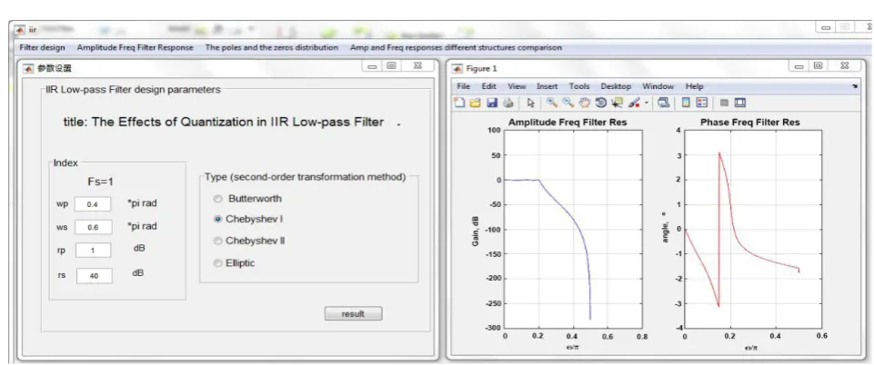
In this example, choose the IIR Cheby I low-pass filter, bandpass frequency wp = 0.4π, stopband frequency ws = 0.6π, bandpass filters maximum attenuation rp = 1DB, stopband filters minimum attenuation rs = 4 0 DB, sampling frequency fs = 1 Hz. Filters are designed with these parameters.
Click result button the amplitude-frequency and phase-frequency filters res-ponses are drawn curve like Figure 3. This method can be used to design high-order filters, and the effects of quantization effects on the zero-pole of the filter system can be clearly observed [6][7].
3.1.1. Statistical Analysis of Frequency Response Deviation
The amplitude-frequency characteristics of the quantized coefficients of the dig-ital filter deviate from the original amplitude-frequency characteristics, and this deviation is related to the quantized word length.
( )
0( )
( ) ( )
01 1 ˆ ˆ , ˆ 1 1 M M i i i i i i N N i i i i i i
b z B z b z
H z H z
A z
a z a z
− − = = − − = = − −
∑
∑
∑
∑
[image:4.595.61.540.471.702.2]= = = (1)
DOI: 10.4236/oalib.1104719 5 Open Access Library Journal Figure 3. Designed amplitude & phase frequency response.
From Figure 3, amplitude & phase frequency response is already designed af-ter the coefficients are quantized by 4 bits, the corresponding ampli-tude-frequency response has been seriously distorted, its attenuation characte-ristics have been degraded, and the distortion of the amplitude-frequency re-sponse after 8-bit quantization has been significantly reduced. After the 32-bit quantization, the amplitude-frequency response has approached the original amplitude-frequency response. Figure 4 can be seen that the quantization of the coefficients will distort the amplitude-frequency response, and the method of reducing the errors is to increase the quantized word length.
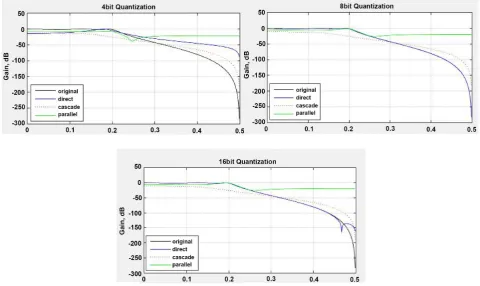
3.1.2. Quantization Effect Analysis of Different Structures
Three different structures can be used to implement an IIR filter: direct, cascade, and parallel type. The filter coefficients are quantized, and the deviation of the amplitude and frequency characteristics of the processed filters from the original amplitude-frequency characteristics is also closely related to the implementation structure. Through programming, draw a comparison chart of the ampli-tude-frequency response when different structures are implemented, and dis-tinguish them with different colors.
As can be seen from Figure 5, whether it is 4 bit quantization or 8 bit quanti-zation, the effect of cascade and parallel implementation is far better than the direct implementation. At the same time, the parallel implementation is slightly better than the cascade implementation. Parallel implementation is the smallest error.
3.2. The Zero-Pole Method
DOI: 10.4236/oalib.1104719 6 Open Access Library Journal Figure 4. Different word lengths after quantization.
Figure 5. Frequency response of different structures.
[image:6.595.58.539.351.637.2]DOI: 10.4236/oalib.1104719 7 Open Access Library Journal Figure 6. The zero-pole filter design interface.
However, this method is not suitable for designing high-order digital systems. Designing low-order systems is not a significant effect of observing quantization effects on the pole-zero of IIR filters.
3.2.1. The Effects of Coefficient Quantization Influence on the Zero-Pole Method
The stability of the filter depends on the position of the pole. If the quantization error of the coefficient causes the pole within the unit circle to move to or away from the unit circle, the characteristic of the filter is different from the required frequency response, and the stability of the filter is affected.
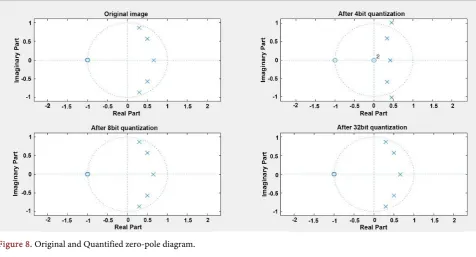
For example, the band-pass filter with conjugate poles near the imaginary axis is shown Figure 7(a), and the low-pass filter with conjugate poles near the real axis is shown Figure 7(b).
As a result of the destruction, it is clear that this is most likely to occur in the poles closest to the unit circle within the unit circle. Comparing the four plots in
Figure 8, we can see that the poles of the original system are all within the unit garden.
After the 4 bit quantization, some poles go beyond the unit circle, and the system becomes stable and unstable. After 8 bit quantization, the system is sta-ble. After the coefficients of the IIR digital filter are quantized, the poles may go out of the unit circle, making the system unstable, increasing the quantized word length, improving stability, and reducing errors.
3.2.2. Poles of Quantized Second-Order Systems
The cascade or parallel forms are based on second-order modules. Despite the simple structure of a second-order system, there are still several ways to imple-ment it such that the quantization effects on the pole locations can be diminished. Consider a second order system
( )
1 21 2
1 1 H z
a z− a z−
=
+ + therefore the
coeffi-cients 2 2
r =a , cos 1 2
a
DOI: 10.4236/oalib.1104719 8 Open Access Library Journal Figure 7. The pole position response is inversely proportional to the dis-tance between poles. (a) Long disdis-tance from poles; (b) Short disdis-tance from poles.
Figure 8. Original and Quantified zero-pole diagram.
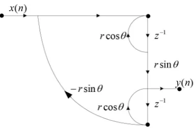
Figure 9. Direct-form implementation of a com-plex-conjugate pole pair.
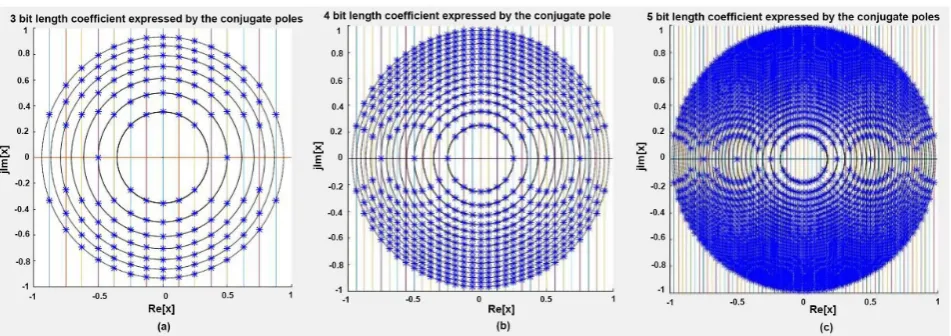
Notice that for the direct form, the grid is rather sparse around the real axis. The plots of Figure 10 are, of course, symmetrically mirrored into each of the other quadrants of the z-plane. Thus poles located around θ =0 or θ π=
maybe shifted more than those around θ π= 2. It is always possible that the
[image:8.595.59.536.254.511.2] [image:8.595.277.471.520.592.2]DOI: 10.4236/oalib.1104719 9 Open Access Library Journal Figure 10. Pole locations for the second-order IIR direct-form system of Figure 9. (a) Three-bit quantization (b) Four-bit quanti-zation (c) Five-bit quantiquanti-zation.
3.2.3. Coupled-Form Implementation of Complex-Conjugate Pair
An alternative second-order structure for realizing poles at z re= jθ and
j
z re= −θ is shown in Figure 11. This structure is referred to as the coupled form for the second-order system.
It is easily verified that the systems of Figure 10 and Figure 12 have the same poles for infinite-precision coefficients. Since these quantities are the real and imaginary parts, respectively, of the pole locations, the quantized pole locations are at intersections of evenly spaced horizontal and vertical lines in the z-plane.
Figure 12(a)-(c) show the possible pole locations for 3-bit to 5-bit quantization, respectively. In this case, the density of pole locations is uniform throughout the interior of the unit circle. Twice as many constant multipliers are required to achieve this more uniform density. In some situations, the extra computation might be justified to achieve more accurate pole location with reduced word length.
4. Conclusions
The quantization effect affects the performance of the IIR digital filter, which changes the zero-pole position of the filter system. After the quantization, the system pole may go beyond the unit cell, which makes the system unstable. After the quantification, the amplitude-frequency response of the system may be se-verely distorted, and the attenuation characteristics of the system may be de-graded.
DOI: 10.4236/oalib.1104719 10 Open Access Library Journal Figure 11. Coupled-form implementation of a
com-plex-conjugate pole pair.
Figure 12. Pole locations for coupled-form second-order IIR system of Figure 11. (a) Three-bit quantization (b) Four-bit quanti-zation (c) Five-bit quantiquanti-zation.
the effect of the structure on stability. In this paper, the digital filter is designed by using the amplitude-frequency characteristic method and zero-pole method of MATLAB programming, and the coefficient quantization effect and the oper-ation and quantizoper-ation effect of the digital filter are analyzed.
That is to say, the zero-pole distribution and amplitude-frequency response of the system after quantizing the coefficients of the system function of IIR digital filter with a certain word length, and the frequency response of the system after quantizing the coefficients under the direct, parallel and cascade structures, as well as the related figures of the operational quantization effect are drawn. The effect of coefficient quantification on the position of zeros and poles is closely related to the distribution of zero and pole positions and the structure of the fil-ter. Increasing the quantized word length allows the system pole to be close to the unit circle, improving the frequency response characteristics.
[image:10.595.72.539.239.405.2]DOI: 10.4236/oalib.1104719 11 Open Access Library Journal
References
[1] Oppenheim, A.V., Schafer, R.W. and Buck, J.R. (1998) Discrete-Time Signal Processing. 2nd Edition, Prentice-Hall, Inc., Upper Saddle River, New Jersey. [2] Lyons, R.G. (2011) Understanding Digital Signal Processing. 3rd Edition, Upper
Saddle River, New Jersey.
[3] Zhang, Z. (2013) Analysis of Quantization Effects on the Performance of the IIR Digital Filter. Journal of School of Electronics & Information, No. 6, 25-45.
[4] Ingle, V.K. and Proakis, J.G. (2008) Digital Signal Processing and Matlab Imple-mentation. 2nd Edition, Publishing House of Electronics Industry, Beijing.
[5] Chapman, S.J. (2008) MATLAB® Programming for Engineers. 2nd & 4th Edition, CL Engineering, CA, USA.
[6] Smith, S.W. (1999) The Scientist and Engineer’s Guide to Digital Signal Processing. 2nd Edition, CL Engineering, CA, USA.
[7] Parhi, K.K. (2007) VLSI Digital Signal Processing Systems: Design and Implementa-tion. John Wiley & Sons, California Technical Publishing.
[8] Hsiao, T. (2014) Digital Signal Processing Lecture 15, Finite-Precision Numerical Effects.National Chiao Tung University.
[9] Singh, R. and Arya, K. (2012) Genetic Algorithm for the Design of Optimal IIR Dig-ital Filters. Department of Electronics and Communication Engineering, GJUS&T, Hisar, India.