ISSN Online: 2327-5901 ISSN Print: 2327-588X
DOI: 10.4236/jpee.2019.72002 Feb. 2, 2019 14 Journal of Power and Energy Engineering
Fault Waveform Regenerator and Its Digital
Closed-Loop Modification Technique
Xiaoming Sun
Department of Electrical Engineering, Chongqing Water Resources and Electric Engineering College, Chongqing, China
Abstract
In order to provide a novel and more effective alternative to the commonly used relay protection testing device that outputs only the sinusoidal testing signals, the concept of fault waveform regenerator is proposed in this paper, together with its hardware structure and software flow chart. Fault waveform regenerator mainly depends on its power amplifiers (PAs) to regenerate the fault waveforms recorded by digital fault recorder (DFR). To counteract the PA’s inherent nonlinear distortions, a digital closed-loop modification tech-nique that is different from the predistortion techtech-nique is conceived. And the experimental results verify the effectiveness of the fault waveform regenerator based on the digital closed-loop modification technique.
Keywords
Fault Waveform Regenerator, Digital Closed-Loop Modification Technique, Power Amplifier, Relay Protection Testing Device
1. Introduction
In order to ensure the safety, reliability and stability of the operation of power system, various types of relay protection as well as supervisory equipment are deployed in power system. However, every now and then faults would occur unavoidably, which are likely to cause complex transient processes or oscilla-tions because there are large numbers of capacitors and inductors spreading all over the power grid. In addition, the switch-on and switch-off of the large capaci-tive or induccapaci-tive loads would also give rise to high-order harmonics. All these dis-turbances may have detrimental effects on the operations of relay protection and supervisory equipment nearby. Therefore, recording the harmful wave-forms of faults and the related transient processes in power grid is of great help to the fault causal investigations, and this is achieved by digital fault recorders (DFR).
How to cite this paper: Sun, X.M. (2019) Fault Waveform Regenerator and Its Digi-tal Closed-Loop Modification Technique. Journal of Power and Energy Engineering, 7, 14-26.
https://doi.org/10.4236/jpee.2019.72002 Received: January 11, 2019
Accepted: January 29, 2019 Published: February 2, 2019 Copyright © 2019 by author(s) and Scientific Research Publishing Inc. This work is licensed under the Creative Commons Attribution International License (CC BY 4.0).
DOI: 10.4236/jpee.2019.72002 15 Journal of Power and Energy Engineering However, if we can regenerate these waveforms by a certain device with respect to the data recorded by DFR, it will be even more helpful because the regene-rated fault waveforms can be directly used to test relay protection and supervi-sory equipment in a much more realistic environment than the commonly used testing methods based on software simulation [1] [2] or relay protection testing devices [3] [4], where the behavior of the tested relay protection and supervisory equipment and sometimes the cause of fault can be diagnosed in detail, simpli-fying the parameters tuning process of relay protection and supervisory equip-ment, and making the parameters more reliable and accordant to reality. In this paper, the concept of fault waveform regenerator is proposed to put the idea above into practice, and it is a device that can regenerate fault waveforms ac-cording to the data recorded by DFR. In fault waveform regenerator, power am-plifiers (PAs) are indispensable component to amplify the fault waveforms to the voltage and current levels of the secondary sides of potential transformer (PT) and current transformer (CT) for the fact that relay protection and supervisory equipment are connected to PT and CT’s secondary sides. In addition, fault waveforms generally consist of intricate harmonic component spreading in a wide bandwidth, while PAs are inevitably accompanied by the inherent nonli-nearity due to their finite bandwidth. Therefore, a digital closed-loop modifica-tion technique is further proposed to modify PAs’ nonlinear errors. The digital closed-loop modification technique includes three basic steps: 1) output fault waveforms directly through PAs regardless of the nonlinear distortion; 2) sample the output waveforms from the feedback channels, and compare them with the accurate ones and calculate errors; 3) modify the subsequent fault waveforms with respect to the errors; 4) output the modified fault waveforms through PAs to obtain the accurate fault waveforms. It should be noted that the four steps above are executed dynamically in real application.
DOI: 10.4236/jpee.2019.72002 16 Journal of Power and Energy Engineering In the following, the fundamental principle of digital closed-loop modification technique is discussed in Section 2. In Section 3, the hardware layout of fault waveform regenerator is presented, including central controller, auxiliary con-troller, isolation device, PA and power supply. Accordingly, in Section 4, the software realization considerations are proposed. In Section 5, the experiment is carried out to verify the performance of fault waveform regenerator. Finally Sec-tion 6 concludes the paper with meaningful comments.
2. Digital Closed-Loop Modification Technique
Because PAs have inherent nonlinear characteristics, theoretically, it can be con-sidered as a nonlinear system. For clarity, a PA is described as the following vir-tual function F:
( )
F
=
y x (1)
where x = [x1, x2, …, xN]T is the column vector of the input time series of the
recorded fault waveforms arranged with respect to the sampling time, the nota-tion T denotes the transposinota-tion of matrix, and N is the data number or the length of the time series; in accordance, y = [y1, y2, …, yN]T is the column vector
of the output time series of the feedback waveforms. Obviously, the ideal or ex-pected output of PA should be
K
∗=
y x (2) where K is the linear amplification coefficient of PA, and in practice there is a deviation between F(x) and Kx due to the existence of the PA’s nonlinearity.
To counteract PA’s nonlinearity, the digital closed-loop modification tech-nique is conceived by the author, which includes the following four steps.
1) Divide x into several short segments, named as subseries. For example, di-vide x into subseries of equal length, i.e.x = [xs1, xs2, …, xsM], thereinto, M is the
total number of subseries, the ith subseries xsi= [x(i – 1)L + 1, x(i – 1)L + 2, …, xiL]T, i =
1, 2, …, M, and L is the length of the subseries and LM = N.
2) Amplify the first subseries xs1 through PA, and meanwhile, sample the
output waveform, i.e. obtain the corresponding output subseries ys1; calculate the
deviation (also expressed in subseries) between the actual output and the ex-pected output es1:
( )
s1= s1∗ − s1=K s1−F s1e y y x x (3)
By Equation (3), PA’s characteristic, i.e. the functional relation F(⋅), can be identified and is denoted as Fˆ(⋅) for distinction.
3) Estimate the possible deviation between the second output subseries and the second expected output according to the identified Fˆ(⋅) and the second
input subseries xs2:
( )
s2 s2 ˆ s2
ˆ =K −F
e x x (4)
Then modify the second input subseries:
(
)
s2=u ˆ ,s2 s2
DOI: 10.4236/jpee.2019.72002 17 Journal of Power and Energy Engineering where u(⋅) is the modification function with two variables, and xs2 is the
mod-ified xs2. Similarly, u(⋅) cannot always be described as a simple and specific
ex-pression, and therefore an abstract form is adopted here.
4) Repeat Steps 2) and 3), replacing xs1 by xs2 and xs2 by xs3 respectively,
un-til the last input subseries xsM is reached. This produces the effect that the
sub-sequent input subseries are modified according to PA’s characteristic before outputted, and thus the actual output subseries can progressively approach the expected output subseries.
To sum up, the fundamental principle of fault waveform regenerator based on digital closed-loop modification technique is as Figure 1. Firstly, by various means of digital communication, e.g. Ethernet, RS-232/RS-485, USB, etc., the fault waveform data recorded by DFR are transmitted to the inner memory buf-fer of fault waveform regenerator and adjusted to form x vector from the origi-nal storage format (e.g. the common format for transient data exchange (COMTRADE) [8] [9]). Then, x is modified by the modification function u(⋅) as
described in Equation (5), and here x is turned into the modified form x. Fi-nally, x is inverted from digital signal back to analog signal by digi-tal-to-analog converter (DAC) to drive the PA to output the regenerated fault wave-form, which is linked to the tested relay protection or supervisory equipment. Meanwhile, digital signal y is acquired from analog-to-digital converter (ADC) by sampling the output waveform, and the microproces-sor/microcomputer (MP/MC) takes y to identify Fˆ(⋅) so as to modify x ac-cording to Equations (4) and (5).
3. Hardware Layout
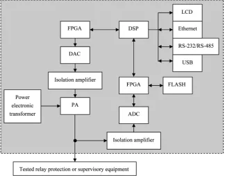
For better realizing digital closed-loop modification technique, the hardware layout of fault waveform regenerator plays also an important part, which is shown in Figure 2.
3.1. Central Controller
In this paper, one of Texas Instruments’ (TI) digital signal processors (DSPs), TMS320 LF2407A, is chosen as the central controller of fault waveform regene-rator because of its outstanding performance of numerical computation and low cost. The DSP in Figure 2 is dedicated to realizing digital closed-loop modifica-tion technique in real time, and coordinating the digital-signal output to DAC and the digital-signal feedback from ADC. Besides, DSP takes the spare time among the main tasks to complete the man-machine interfacing work, including displaying important operation parameters on liquid crystal display (LCD), and fetching the fault waveform data or sending the output waveform data from or to the outer personal computer via Ethernet, RS-232/RS-485 or USB.
3.2. Auxiliary Controller
DOI: 10.4236/jpee.2019.72002 18 Journal of Power and Energy Engineering
Figure 1. The fundamental principle of fault waveform regenerator based on digital
closed-loop modification technique.
Figure 2. The hardware layout of fault waveform regenerator.
to ensure the reliability of its operation, it is better to introduce an auxiliary controller to help it deal with some other simple but important tasks. In this pa-per, a field programmable gate array (FPGA), Altera’s low-cost EP1C6, is chosen as the auxiliary controller, and considering its unique capability of real-time and parallel operation, its main tasks are to implement the high-speed synchronous data exchange between DSP and the ADCs/DACs in multiple channels. Besides, FPGA also helps DSP handle some peripheral interface works, including address decoding and peripheral expanded memory (e.g. FLASH) accessing without spending extra time. The FLASH memory mentioned here is necessary because it is used to reliably preserve the fault waveform data and important system pa-rameters even when the system encounters a power outage.
3.3. Isolation Device
[image:5.595.211.536.228.482.2]peri-DOI: 10.4236/jpee.2019.72002 19 Journal of Power and Energy Engineering odic component) and direct current (DC) component (i.e. nonperiodic compo-nent), and the DC component may be eliminated or distorted by instrumental CT and PT or traditional current and voltage sensors. Due to this, an isolation device that can feed through both AC and DC components is required in the feedback channel so as to transmit the output waveform to DSP without extra errors. In addition, on the printed circuit board (PCB) the DACs are usually configured with other low-power, low-voltage electronic devices on the same ground plane, and for the electronic devices’ safety, it is very essential to isolate the low-power, low-voltage ground plane from the high-power, high-voltage ground plane of PAs. For the two reasons above, in this paper, the isolation am-plifiers, Burr-Brown’s (BB) new product ISO124, are introduced in both the feedback and output channels, which are of lower price and higher precision than Hall sensors and are of simpler circuit design than linear analog optocoup-lers.
3.4. Power Amplifier
Fault waveforms are divided into two kinds, i.e. voltage waveform and current waveform, and therefore the PAs of fault waveform regenerator should be de-signed accordingly as voltage-type and current-type as well. Commonly, cur-rent-type PA has larger nonlinear distortion than voltage-type PA because the larger current of current-type PA may produce more heat, causing larger varia-tions of the circuit parameters. Therefore, larger effort has to be put on de-signing current-type PA, while voltage-type PA can be treated as the simplified type of current-type PA and directly adopts the control strategy of cur-rent-type PA. Owing to the digital closed-loop modification technique pro-posed in this paper, PAs’ accuracy requirement is relaxed so that the designing difficulty is reduced.
3.5. Power Supply
DOI: 10.4236/jpee.2019.72002 20 Journal of Power and Energy Engineering
4. Software Realization
4.1. Adaptive Neural-Fuzzy Inference System
From Section 2, it is seen that the difficulty of digital closed-loop modification technique is to identify Fˆ(⋅) and to calculate the modified subseries x. As mentioned, ANFIS that integrates the advantages of both artificial-neural net-work (ANN) and fuzzy inference system (FIS) is a preferable solution. On one hand, ANN is famous for its adaptive learning capability, however, it should be supervised and guided carefully to finish the learning procedure rapidly and en-sure the convergence in global optimum. On the other hand, FIS is good at con-trolling unknown or half-known object by simulating the manual operation of human beings according to the control rule table; however, the control rule table is usually very difficult to acquire and optimize in practice. Therefore, it is wise to integrate ANN and FIS together, using ANN to learn and produce control rule table for FIS while using FIS to guide ANN, and the result is ANFIS [10] [11]. ANFIS shows a strong ability to approach any nonlinear functions within a finite range so that it is used to approximate the nonlinear half-known object Fˆ
(⋅) and replace Fˆ(⋅) to calculate x. Moreover, ANFIS can also take advantage of its adaptability to track and counteract the nonlinear and unpredictable varia-tions of the circuit parameters resulted from devices, power supply and load. Because the detailed realization procedures of ANFIS can be found in many lite-ratures, they are omitted in this paper for brevity.
4.2. Control Principle Based on ANFIS
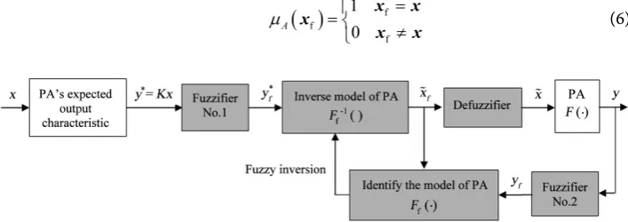
[image:7.595.183.537.578.703.2]The control principle of fault waveform regenerator based on ANFIS is shown in Figure 3, where the subscript “f” is used to distinguish the fuzzy functions and fuzzy subseries or vectors from their “clear” types.
Firstly, the fault waveform data vector x and the output waveform data vector y are fuzzified by Fuzzifiers No. 1 and No. 2 and become two fuzzy vectors xf
and yf that can be dealt with by the FIS part of ANFIS. Considering that x
con-sists of the precise fault waveform data, it is reasonable to use the clear quantities directly as fuzzy ones, and therefore, Fuzzifier No. 1 adopts the single-point fuzzy set as the fuzzifying method:
( )
ff
f
1 0 A
µ = =
≠
x x x
x x (6)
DOI: 10.4236/jpee.2019.72002 21 Journal of Power and Energy Engineering Because feedback samples in y are mixed with stochastic noise, Fuzzifier No. 2 adopts the normal distribution function, i.e. Gaussian function fuzzy set, as the fuzzifying method:
( )
( ) 2 f 2 2 fB e σ
µ = − −
y y
y (7)
In Equations (6) and (7), A and B are the linguistic variables that can take various linguistic terms.
After fuzzification, xf and yf together with PA’s fuzzy model Ff(⋅), i.e. the
open-loop model of fault waveform regenerator, can be expressed by the follow-ing fuzzy rules:
( )
f f f
R : ifj x isaj andF ⋅ is , thencj y isbj (8)
where j = 1, 2, …, P, and P is the number of fuzzy rules, membership functions and linguistic terms; because a big P is not bound to produce better result than a small P[12] [13], for computational convenience, it is recommended to choose a small P, e.g. P = 3 to 7; aj, bj and cj are linguistic terms, i.e. the specific fuzzy sets,
related to A, B and C (the linguistic variables of PA’s fuzzy model), and they have the following relationships (take A and aj for example, and B and bj, C and
cj have the similar relationships):
terms
, 1,2, ,
, NM, NS, ZE,PS,PM,
j
P
j
A a j P
a = = ∈
(9)
where NM, NS, ZE, PS and PM in the second formula are the abbreviations of Negative Medium, Negative Small, Zero, Positive Small and Positive Medium, respectively. Based on Mamdani fuzzy implication [14] [15], Equation (8) can be further expressed as
( )
( )
f f f f f f
Rj =x ×F ⋅ → y =x ×F ⋅ ×y (10)
where × is the direct product not the traditional multiplication, and → is the
implication conjunction not the function mapping symbol.
By Equation (10), PA’s fuzzy model Fˆ(⋅) can be identified and is notated as
ˆ
F(⋅). Then, the inverse type of Fˆ ( )f ⋅ , noted as ˆ 1
f
F− (⋅), can be obtained from the fuzzy-inversion calculation of Equation (10):
( )
( )
1 1 1
f f f f f f
R−j =y ×F− ⋅ → x = y ×F− ⋅ ×x (11)
and the corresponding fuzzy rules become
( )
1 1
f f f
R : if−j y isbj andF− ⋅ is , thencj x isaj (12)
Now, the expected fuzzy output yf∗ can be substituted into Equation (11) or (12) to produce the corresponding xf, which implies that if xf is defuzzied
and inputted back into the PA, then the accurate yf =yf∗ can be generated, making eˆ = 0.
DOI: 10.4236/jpee.2019.72002 22 Journal of Power and Energy Engineering the functions of Equations (4) and (5), and implicitly integrate the procedures of model identification, model inversion and signal modification. Therefore, ANFIS serves as both an identifier and a modifier, integrally and dynamically realizing the goals of digital closed-loop modification technique.
4.3. Real-Time Realization
Although ANFIS can effectively realize digital closed-loop modification tech-nique, great computational burden has fallen on DSP, making it difficult to meet the requirement of real-time control. Therefore, two empirical measures may be introduced to lighten the computational burden of DSP.
1) Confine the length of the subseries processed by ANFIS every time accord-ing to DSP’s computational capability. Thus, every new input subseries xfs(i+1) (i =
1, 2, …, M – 1) can be modified (noted as xfs(i+1)) by Equation (11) or (12) with
the preceding input subseries xfsi and the corresponding output subseries yfsi
be-fore defuzzified and inputted to PA.
2) Reduce the learning times of ANFIS in terms of a certain error threshold. Because the learning procedure is the most time-consuming part of ANFIS, moderately reducing the learning times when the errors are relatively small and negligible may make an agreeable compromise between the computational cost and the expectation of zero errors. Moreover, reducing the learning times can also prevent ANFIS from over fitting PA’s model [16] [17], which may cause system instability.
4.4. Algorithm Flow
To sum up the discussions of the previous subsections, the algorithm flow of software realization for fault waveform regenerator can be depicted as Figure 4, where the processes of fuzzification and defuzzification are omitted for clarity.
5. Experimental Results
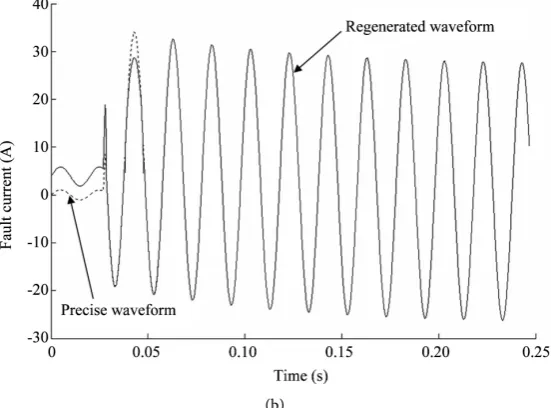
con-DOI: 10.4236/jpee.2019.72002 23 Journal of Power and Energy Engineering dition) the regenerated fault waveform approaches the precise fault waveform rapidly and then the two match together steadily, meaning that the nonlinear distortion is modified effectively.
Figure 4. The algorithm flow of software realization for fault waveform regenerator.
(a)
Y
Get fault-waveform data from DFR Begin
Subseries division
Input subseries xsi
Model identification and inversion based on ANFIS
Get xs(i+1) and calculate the expected output
Calculate modified Calculate error esi
Adjusting learning times of ANFIS
DOI: 10.4236/jpee.2019.72002 24 Journal of Power and Energy Engineering
(b)
Figure 5. Fault waveforms regenerated by fault waveform regenerator.
(a) Without ANFIS-based digital closed-loop modification; (b) With ANFIS-based digital closed-loop modification.
6. Conclusion
The fault waveform regenerator together with the digital closed-loop modifica-tion technique based on ANFIS is proposed in this paper, and the hardware layout and software realization method are discussed. The experimental results have verified the effectiveness of the fault waveform regenerator and the feasibil-ity in application of adjusting and testing relay protection and supervisory equipment. The various adjusting and testing examples will be carried out in the future work and presented in another paper.
Acknowledgements
This research is supported by the Science and Technology Research Project of Chongqing Educational Committee (KJ1603605) and the Natural Science Fund Project of Yongchuan District Science and Technology Committee (Ycstc, 2016nc3001).
Conflicts of Interest
The author declares no conflicts of interest regarding the publication of this pa-per.
References
[1] Zhao, J.H., Xu, Y., Luo, F.J., Dong, Z.Y. and Peng, Y.Y. (2014) Power System Fault Diagnosis Based on History Driven Differential Evolution and Stochastic Time Domain Simulation. Information Sciences, 275, 13-29.
http://dx.doi.org/10.1016/j.ins.2014.02.039
[2] Dos, S.A. and Barros, M.T.C.D. (2015) Stochastic Modeling of Power System Faults.
[image:11.595.235.511.76.280.2]DOI: 10.4236/jpee.2019.72002 25 Journal of Power and Energy Engineering
http://dx.doi.org/10.1016/j.epsr.2015.04.015
[3] Glazyrin, V.E., Osintsev, A.A., Litvinov, I.I. and Frolova, E.I. (2018) Verification of Distance Relay of Relay Protection and Emergency Control Automation Equipment in Asynchronous Mode by Standard Devices of the RETOM Test Complex. Power Technology and Engineering, 52, 242-247.
http://dx.doi.org/10.1007/s10749-018-0939-8
[4] Sun, X.M., Peng, W.F. and Qin, L. (2017) ANFIS Digital Predistorter for Linear Power Amplifier in Protective Relay Test Device. Recent Advances in Electrical and Electronic Engineering, 10, 233-241.
http://dx.doi.org/10.2174/2352096510666170601121644
[5] Feng, X.W., Feuvrie, B., Descamps, A.S. and Wang, Y. (2014) Digital Predistortion Technique Based on Non-Uniform MP Model and Interpolated LUT for Linearising PAs with Memory Effects. Electronics Letters, 50, 1882-1884.
http://dx.doi.org/10.1049/el.2014.2130
[6] Liang, K.F., Chen, J.H. and Chen, Y.J.E. (2014) A Quadratic-Interpolated LUT-Based Digital Predistortion Technique for Cellular Power Amplifiers. IEEE Transactions on Circuits and Systems II: Express Briefs, 61, 133-137.
http://dx.doi.org/10.1109/TCSII.2013.2296194
[7] Novak, A., Simon, L. and Lotton, P. (2018) A Simple Predistortion Technique for Suppression of Nonlinear Effects in Periodic Signals Generated by Nonlinear Transducers. Journal of Sound and Vibration, 420, 104-113.
http://dx.doi.org/10.1016/j.jsv.2018.01.038
[8] IEEE Std C37.111 (IEC 60255-24 Edition 2.0) (2013) IEEE/IEC Measuring Relays and Protection Equipment Part 24: Common Format for Transient Data Exchange (COMTRADE) for Power Systems. Institute of Electrical and Electronics Engineers,
USA, 1-73. http://dx.doi.org/10.1109/IEEESTD.2013.6512503
[9] Macieira, G.L. and Coelho, A.L.M. (2017) Evaluation of Numerical Time Overcur-rent Relay Performance for CurOvercur-rent Transformer Saturation Compensation Me-thods. Electric Power Systems Research, 149, 55-64.
http://dx.doi.org/10.1016/j.epsr.2017.04.005
[10] Kharb, R.K., Shimi, S.L., Chatterji, S. and Ansari, M.F. (2014) Modeling of Solar PV Module and Maximum Power Point Tracking Using ANFIS. Renewable and Sus-tainable Energy Reviews, 33, 602-612. http://dx.doi.org/10.1016/j.rser.2014.02.014
[11] Falehi, A.D. and Mosallanejad, A. (2017) Dynamic Stability Enhancement of Inter-connected Multi-Source Power Systems Using Hierarchical ANFIS Control-ler-TCSC Based on Multi-Objective PSO. Frontiers of Information Technology and Electronic Engineering, 18, 394-409. http://dx.doi.org/10.1631/FITEE.1500317
[12] Lee, C.C. (1990) Fuzzy Logic in Control Systems: Fuzzy Logic Controller I. IEEE Transactions on Systems, Man and Cybernetics, Systems, Man and Cybernetics, 20, 404-418. http://dx.doi.org/10.1109/21.52551
[13] Lee, C.C. (1990) Fuzzy Logic in Control Systems: Fuzzy Logic Controller II. IEEE Transactions on Systems, Man and Cybernetics, Systems, Man and Cybernetics, 20, 419-435. http://dx.doi.org/10.1109/21.52552
[14] Zhou, B.K., Xu, G.Q. and Li, S.J. (2015) The Quintuple Implication Principle of Fuzzy Reasoning. Information Sciences, 297, 202-215.
http://dx.doi.org/10.1016/j.ins.2014.11.024
[15] Gabroveanu, M., Iancu, I. and Coşulschi, M. (2016) An Atanassov’s Intuitionistic Fuzzy Reasoning Model. Journal of Intelligent and Fuzzy Systems, 30, 117-128.
DOI: 10.4236/jpee.2019.72002 26 Journal of Power and Energy Engineering [16] Zhang, L., Wang, F.L., Xu, B., Chi, W.Y., Wang, Q.Y. and Sun, T. (2018) Prediction of Stock Prices Based on LM-BP Neural Network and the Estimation of Overfitting Point by RDCI. Neural Computing and Applications, 30, 1425-1444.
http://dx.doi.org/10.1007/s00521-017-3296-x
[17] Srivastava, N., Hinton, G., Krizhevsky, A., Sutskever, I. and Salakhutdinov, R. (2014) Dropout: A Simple Way to Prevent Neural Networks from Overfitting.