GLUI
wi
t
h
Leveragi
ng
behavi
oural
domai
n
model
s
i
n
Model
-Dri
ven
User
I
nt
erf
ace
Devel
opment
Supervi
sors
dr.
L.
Ferrei
ra
Pi
res,
Uni
versi
t
y
of
Twent
e
prof
.
dr.
i
r.
A.
Rensi
nk,
Uni
versi
t
y
of
Twent
e
i
r.
H.
V.
Nguyen,
I
NG
Jul
i
,
2018
Pet
er
Wessel
s
Mast
er
Thesi
s
Abstract
Due to the introduction of a wide-range of complex interaction styles and devices, potentially reaching a large and diverse user group, offering a con-sistent user experience with a user interface has become increasingly com-plex. Therefore, the traditional approach of implementing user interaction directly into the implementation technology potentially leads to version inconsistency and high maintenance costs.
In this research, we investigate how a Model-Based User Interface Devel-opment (MBUID) approach can be applied that leverages the characteris-tics of behavioural domain models, resulted from a Domain-Driven Design (DDD) approach, to generate verifiable functionality of a front-end appli-cation for multiple platforms and different modalities while business ana-lysts with a technical background are able to specify workflows that needs to be integrated.
Complexity is dealt with by separating domain logic from the implemen-tation details. For this process, separate abstraction levels are defined and business logic is encapsulated in behavioural domain models. Three lev-els of abstraction are defined that increasingly refine the specification of the behaviour of a user interface. We examined how model transforma-tions can be defined in this process to semi-automatically transform the source model to a refined target model while preserving the operational semantics. As the behavioural domain model embodies part of the sys-tem behaviour, we examined how we can use these models to define the interaction with the system such that the user can invoke commands to manipulate these models. The combination of the defined models for each abstraction level and the model transformations, the transformation chain, allowed us to examine approaches how behavioural models can be used as a source to generate part of the functionality of an user interface. To be able to preserve the correctness of each model and to generate a fully operational user interface, we focused on defining a sound specification of the task model, the first abstraction level of MBUID. We leveraged multi-ple existing techniques to define the structure, data flow and the interaction with the user and the system. This enabled us to create a sound specifica-tion and to generate an operaspecifica-tional user interface, just as specified in the task model. We used this task model as input for the MBUID process and defined how we can generate applications that contain the same function-ality on different platforms. We leveraged characteristics of behavioural domain models twofold. On one hand, we defined patterns to generate separate task models for commands that can be invoked on these domain objects. On the other hand, we defined an approach to combine these sep-arate task models in a composed task model.
Contents
1 Introduction 7
1.1 Motivation . . . 7
1.2 Problem Statement . . . 7
1.3 Objective . . . 8
1.4 Validation . . . 9
1.5 Structure & Approach . . . 10
2 Background 12 2.1 User Interface . . . 12
2.2 Model-Driven Engineering . . . 14
2.2.1 Model-Driven User Interface Development . . . 14
2.2.2 Domain-Driven Design . . . 16
2.3 User Interface Description Languages . . . 16
2.4 Model Transformation Languages and Technologies . . . 18
2.5 Formal Software specification . . . 21
2.6 Software Verification . . . 22
2.7 Conclusion . . . 22
3 Transformation chain 23 3.1 Overview . . . 23
3.2 Conceptual model of the system . . . 24
3.2.1 Concepts . . . 24
3.2.2 Object Behaviour . . . 25
3.2.3 Actors . . . 25
3.2.4 Example: Transaction processing . . . 26
3.3 Correctness by Construction . . . 30
3.3.1 Building blocks of Correctness by Construction . . . 30
3.4 Integration of new platforms and devices . . . 32
3.5 Conclusion . . . 33
4 Task model 35 4.1 Overview . . . 35
4.2 Task modelling techniques . . . 36
4.2.1 Hierarchical Task Analysis . . . 36
4.2.2 GOMS . . . 37
4.2.3 Groupware . . . 37
4.2.4 ConcurTaskTree . . . 37
4.2.5 MAD . . . 37
4.2.6 Task Oriented Object Design . . . 38
4.3 Workflows in the Structural model . . . 38
4.3.2 Operational Semantics . . . 40
4.4 Interaction Specification Markings . . . 41
4.4.1 User Interaction . . . 41
4.4.2 System Interaction . . . 43
4.5 Dynamic Model . . . 45
4.5.1 Task object . . . 45
4.5.2 Event-Driven Tasks . . . 46
4.5.3 Input/output mapping interaction classes . . . 46
4.6 Implementation . . . 49
4.7 Limitations & Constraints . . . 49
4.8 Conclusion . . . 50
5 User Interface Models 51 5.1 Purpose . . . 51
5.2 Abstract User Interface . . . 51
5.2.1 Abstract Construct Elements . . . 52
5.2.2 Events . . . 53
5.2.3 Event Listener . . . 54
5.3 Concrete User Interface . . . 54
5.3.1 Concrete Construct Elements . . . 54
5.4 Metamodels . . . 56
5.4.1 Abstract User Interface . . . 56
5.4.2 Concrete Graphical User Interface metamodel . . . . 56
5.4.3 State machine . . . 56
5.5 Conclusion . . . 57
6 Model Transformations 61 6.1 Transformation languages . . . 61
6.2 Transformation definitions . . . 62
6.2.1 Taskmodel to Abstract User Interface . . . 62
6.2.2 Abstract to Concrete User Interface . . . 64
6.2.3 Concrete User Interface to Final User Interface . . . . 65
6.3 Conclusion . . . 68
7 Leveraging Domain Models 69 7.1 Generating task model specification . . . 69
7.1.1 Tasks . . . 69
7.1.2 Data Flow . . . 70
7.2 Boilerplate approach . . . 70
7.2.1 Workflow patterns/heuristics . . . 70
7.3 Task model modularity . . . 71
7.3.1 Proxy Model . . . 71
7.3.2 Application Configuration Model . . . 72
7.3.3 Transformation Definition . . . 73
7.4 Limitations & Constraints . . . 73
7.5 Conclusion . . . 74
8.1 Correctness . . . 75
8.2 Validation Properties . . . 76
8.2.1 Task model . . . 76
8.2.2 User Interface Models . . . 77
8.3 OCL Constraints . . . 77
8.3.1 Task model . . . 77
8.3.2 User Interface Models . . . 79
8.4 Validation Tools . . . 80
8.5 Limitation & constraints . . . 80
8.6 Conclusion . . . 80
9 Validation 81 9.1 Goal . . . 81
9.2 Method . . . 82
9.2.1 Implementation . . . 82
9.2.2 Experiments . . . 82
9.3 Exhaustive specification experiment . . . 84
9.3.1 Minor violation . . . 85
9.3.2 Redundant EventListeners . . . 85
9.3.3 Overlapping enumerators . . . 85
9.4 Simple example: Money transfer . . . 85
9.4.1 Choice Container . . . 86
9.5 Real-world case: BuyerFunderAgreement . . . 88
9.5.1 Automatic generated text elements . . . 91
9.5.2 Manual intervention to include back button . . . 92
9.6 Usability of GLUI . . . 92
9.7 Conclusion . . . 92
10 Final Remarks 94 10.1 Conclusion . . . 94
10.2 Future work . . . 95
Appendices 96
A Specification of Bankaccount and Transaction 97
B Obtain Execution Traces Algorithm 98
C Metamodel of Taskmodel 103
D Concrete Graphical User Interface Metamodel 105
E Taskmodel of toy example: Money transfer 107
F Implementation in VueJS 109
Preface
Before you lies the report ”Leveraging behavioural domain models in Model-Driven User Interface development with GLUI”, the result of a research project conducted at ING. It has been written as part of the final project for the master’s programme Computer Science at the University of Twente withSoftware Technologyas specialisation. I was engaged in this research from January to June 2018.
This project has been initiated together with Joost Bosman, who intrigued me with his ideas about introducing new software technology in the fi-nancial domain. From that point, I was determined to become part of this transition. The innovative spirit and determination of the development team to radically change the software landscape had a significant positive impact on this project.
I would like to thank my supervisors for their guidance and support dur-ing the process. From ING, Viet Nguyen: my project benefitted from your enthusiasm about my research and the project. From the University, Lu´ıs Ferreira Pires and Arend Rensink: I have always appreciated your con-structive feedback on my approach and my report. I want to thank the members of the development team at ING, in particular Kevin van der Vlist, Jorryt-Jan Dijkstra, Jeffrey Bruijntjes and Joery Bruijntjes for their feedback and help during my research.
Finally, I would like to thank my parents for their unconditional support during my study and this final project. I would like to thank my friends and family for their support during the past period. As I conducted my re-search remotely, I would like to thank my housemates for the daily portion of welcoming distraction. I appreciate it all sincerely.
This project is the endpiece of 7 years of study at the University of Twente.
It has been one hell of a ride, but a good one.I did not take the easy road, as after my bachelor degree inIndustrial Design, I followed a completely different master’s programme. It has given me a unique background of which I am proud. This master thesis is the result of that.
As always,stay hungry, stay foolish.
Peter Wessels
Chapter 1
Introduction
In this chapter we formulate the objectives and the requirements of the solution, which follows from the problem statement.
1.1
Motivation
The world of software development is changing rapidly. New technologies introduce new possibilities for systems to evolve. Ideally, these technolo-gies should enrich the capabilities of software systems; however, many or-ganisations with large software systems struggle to evolve and maintain their systems. As their systems become increasingly complex, adding new features and using new technologies costs a lot of time and money. Espe-cially in the financial sector, organisations struggle to keep up with new technologies, as new competitors that do not have the burden of having to maintain large legacy systems, are seeking opportunities to offer better services with new technologies.
1.2
Problem Statement
Domain-Driven Designis a method for dealing with complexity of software systems by distilling domain knowledge out of implementation details [1]. By modelling the domain knowledge separate from the implementation, domain experts can use their knowledge and modelling skills to define the characteristics of (complex) domain concepts. This allows complexity to be tackled at the heart of the software (the domain) by the experts who know the domain best.
In this research, we focus on the development of a multi-user front-end application for a reactive system by using domain-driven design in com-bination with a model-driven approach. We define a front-end applica-tion as an operaapplica-tional user interface that handles both the communicaapplica-tion with the back-end as well as the interaction with the end-user. A multi-user front-end application is defined as an environment in which different types of users interact with each other with a certain goal, for example, a business goal. The problem is that user interface development has become increasingly complex and the traditional approach of developing a user in-terface can potentially lead to version inconsistency and fails to deliver a consistent user experience among different devices and platforms [2]. Various research efforts have been devoted to MBUID. This approach to User Interface (UI) development supports the integration of characteristics of domain concepts in a user interface and deals with the complexity of UIs development. These methods, however, have been developed withstatic
domain models, while a domain-driven approach does necessarily define how domain models are modelled, that is specific to the domain. Thus, domain models defined in a domain-driven approach are not necessarily aligned with MBUID, leaving room for improvement.
Current MBUID approaches mainly use adescriptiveor arelationaldomain model that definesstaticcharacteristics and relations between concepts. A
behaviouraldomain model also includes possible interactions with domain concepts defined as, for example, a state machine that defines different states and transitions of a domain concept. For the development of a front-end application, this offers opportunities regarding the verification of spec-ified behaviour as well as leveraging a behavioural model as a source for (semi-)automatically obtaining the required UI functionality. In this re-search, we define methods to exploit the characteristics of a behavioural domain models to generate verifiable functionality of a front-end applica-tion.
1.3
Objective
Our main objective has been to investigate how to apply a MBUID ap-proach that uses characteristics of behavioural domain models such that the application correctly implements the specified behaviour. To achieve this, we investigated the features of the involved models and model trans-formations with the following requirements:
Requirement 2. The input modelling language allows business analysts with a technical background to produce a software specification of a user interface for different kinds of users.
Requirement 3. Each intermediate model of the transformation chain refers to behaviour of a domain model such that the resulting user interface integrates this behaviour.
Requirement 4. Instances of intermediate models can be verified at design time with respect to both the defined domain concepts as well as user interface logic. The user interface does not allow illegal actions nei-ther should it obstruct users to perform valid actions, as defined in the domain model. The correctness the input model should be veri-fied with respect to the domain model; does the task model complies with the input constrains as defined in the domain model?
Requirement 5. The structure of the transformation chain should account for changes in interaction styles, devices and platform. Developing a new application should not require rewriting existing software com-ponents, nor the software specification, in case the product character-istics, the domain knowledge, remain the same. Instead, new model transformations and dedicated intermediate models should be intro-duced to support the new platform or device.
1.4
Validation
To validate the requirements of the solution we defined for each ment a principle that determines if the solution is conform our require-ments.
Requirement 1. The generated user interface should define a clear inter-face with the system as well as presenting the user with the appro-priate tools to finish the described tasks.
(a) The implementation of the user interface should contain a de-scription of the interface that consists of the input and output conditions of each interaction with the system.
(b) The user interface should contain the user interface construct el-ements as such that the user control the behaviour of the system as well as input and manipulate data.
Requirement 2. Business analysts should be able to define and validate the specification for the user interface autonomously.
Requirement 3. Each intermediate model should define a description of
Requirement 4. The input as well as the intermediate models should be constraint as such that only valid models are accepted. Non-valid models should be rejected as they do not result in a correct imple-mentation. Validation methods should be able to asses the validity of these models.
Requirement 5. Introducing a new platform, device or interaction style should solely involve the definition of new model transformations and possibly new (dedicated) intermediate models.
1.5
Structure & Approach
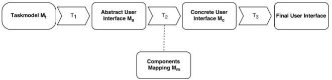
The structure of this report reflects the approach that has been followed during the research. Figure 1.1 depicts the structure of transformation chain labelled with the chapters in which we discuss the features and in-volved design choices.
In our approach, we first conducted a literature review in which we anal-ysed the concepts involved in this research. Then, we defined the assump-tions on the basic structure of solution, the specification and behaviour of the considered system, and our approach to ensure correctness of the resulting solution. Hereafter, we defined the metamodel of the input mod-elling language and the intermediate user interface models and the model transformations involved in the the process of generating an implementa-tion. Then, we defined approaches to use behavioural domain models as input for the task model. Parallel with these steps, we defined approaches to verify the correctness of the involved models. Finally, we have validated our approach to verify to what extent the solution solves the problem at stake.
Chapter 2 introduces the main concepts of this research to facilitate un-derstanding by the reader. Additionally, the most prominent MBUID approaches has been reviewed.
Chapter 3 presents features of the transformation chain. We define the concepts of each model, an approach to achieve correctness, and how models in the transformation chain can refer to properties of the sys-tem on a conceptual level.
Chapter 4 focuses on a input specification language for thetask model. We introduce a notation to describe workflows, data flow, as well as a method to define the interaction with the system and the user. Chapter 5 presentsuser interface modelsthat refine the task model. We
Concrete UI Model
5
Abstract UI Model
5
T1
6
T2
6
Task Model
4
Behavioural Domain
Model
7
Compose Model
7
T0
7
Mapping Model
[image:11.595.247.362.111.323.2]6
Figure 1.1: Overview of the transformation chain labelled with the chapters where the models and model transformation are discussed
Chapter 6 discusses the model transformations between models of the transformation chain.
Chapter 7 describes how we can usebehavioural modelsto generate parts of the task model.
Chapter 8 discusses methods to verify thecorrectnessof the resulting user interface.
Chapter 9 discusses the experiments that have been carried out tovalidate the transformation chain.
Chapter 2
Background
In this section we provide background information to familiarise the reader with the subject. We highlight the different aspects of the problem at stake.
2.1
User Interface
The User Interface (from hereon referred to as UI) in Human-Computer in-teraction is the mechanism wherein the user can interact with the machine. These interactions allow the user to operate and control the machine while the machine gathers valuable feedback that can help the user. As this def-inition is very broad, many types of user interfaces exist. We discuss the major types of user interfaces:
• Graphical User Interfaces (GUI)presents a graphical representation of the information and the possible controls.
• Command line interfaces (CLI) enables users to interact with the system by giving the system commands in a textual form.
• Virtual Reality User Interfacesenables users to interact with the sys-tem in a virtual world in a 3D environment.
• Tangible User Interfacesbuild upon human skills to manipulate and sense the physical world by integrating the digital and physical world [3].
• Voice Assistent User Interfaces enables users to interact with the system via command-like instructions communicated via voice. WA Voice Assistent User Interface is often combined with a GUI, to give feedback in a graphical manner, whereas devices without such feed-back mechanisms give feedfeed-back via voice.
As the UI is a gateway in which a user can interact with the application, designing a UI requires the designer to cope with the complexity of both the application and the user [4].
Considering that a designer must deal with both worlds (the user and the system) it is not surprising that research shows that UI development of an interactive system has become more time-consuming and therefore more costly. On average the development of such a UI represents 47% of the source code, requires about 45% of the development time and 50% of the implementation time, and covers 37% of the maintenance time [5].
To tackle the problem of designing a UI, different approaches exist. Among others, Vanderdonckt has distinguished 4 major approaches in User Inter-face development [6]:
1. Traditional approachIn this approach, the developer develops a UI by composing views, e.g., windows and web pages, with user inter-face components, e.g., buttons, forms and titles. When the functions of the system are developed, these views are expanded such that the UI can call system functions and become operational.
2. Programming by demonstrationBy adding actions to the UI the de-veloper can demonstrate how the UI interacts with the user. This approach is very similar to the traditional approach, except that it adds the possibility to assess the usability of the UI at design-time. 3. Model-based approach (MBUIDE)By separating UI-related concerns
into formal declarative models a functioning UI can be generated. Once each model is defined, the code generation process can be au-tomated.
4. Task-based approach Very similar to the previous approach is the task-based approach except that the task-model is first specified. Us-ing a task-model, other models can be derived, refined or specified. The development of user interfaces has become more complex due to some serious challenges [2]. Vanderdonckt presents an analysis of variables that are at the root of this increase of complexity.
• Diversity of users. An interactive system can no longer consider users to be similar, as they show differences in terms of skills and expertise with regard to operating an interactive system through a user interface.
• Richness of cultures.When dealing with applications that are glob-ally accessible, the UI cannot remain the same for each culture, as cultures can have different languages, different customs or even dif-ferent demands of the UI.
• Heterogeneousness of computing platforms. In the world of soft-ware technologies, new platforms and technologies will be introduced continuously, posing new limitations and constraints on the UI.
• Multiple working environments. Users should be able to interact with the user interface under different circumstances (e.g. light and sound conditions).
• Multiple contexts of use. The context in which a user operates can change. For example, if the user decides to start working on his com-puter and continue working on a task on a mobile device, it would be convenient that the application can adapt to this context change.
Even though some interface development techniques such as universal de-sign [7] and inclusive dede-sign [8], promote dede-signs that fit for the largest possible population, the UI cannot longer be considered as independent of its usage context [9]. This usage context can be defined as a triplet of a user, platform and environment and determines the characteristics of the UI in different contexts [10]. With these challenges in mind, the traditional approach for the design of user interfaces would require many versions of the UI. This potentially leads to version inconsistency and therefore high maintenance costs [11]. Adaptive UIs have been promoted as a solution to offer a consistent UI in changing contexts, as they automatically adapt to the context of use at runtime [9].
2.2
Model-Driven Engineering
Model-Driven Architecture (MDA)is a software development approach in which models have a central role [12]. By structuring specifications ex-pressed as models, transformations can be defined to automate the imple-mentation of the system. The approach is based on separating application domain knowledge and application logic from the underlying platform technology. The basic pattern is to define a Platform-Independent Model (PIM) that captures domain knowledge and a transformation to a Platform-Specific Model (PSM) that maps the domain knowledge to platform-specific implementation details. MDA claims to properly deal with the complexity of large systems and the interaction and collaboration between organisa-tions, people, hardware and software.
2.2.1
Model-Driven User Interface Development
The first generation was motivated by the idea of using one universal UI model that integrates the relevant aspects of a UI. The second generation of systems can be characterised by abstracting aspects of the UI model in separate high-level models like, e.g., dialog, task and presentation mod-els. The introduction of new mobile devices like smartphones and PDAs motivated the third generation of MDUID approaches. The current fourth generation of MDUID approaches focuses on the development of context-aware user interfaces that have the ability to adapt to the user, platform and environment.
The Cameleon Reference Framework (CRF) is a fourth generation MDUID approach and has become widely accepted in the Human Computer Inter-action Engineering community as an approach to structure the develop-ment of UIs supporting multiple contexts of use. The framework adopts a model-based approach by prescribing the development of UIs based on threeOntological models. These ontological models express context-of-use configurations, domain concepts and adaptation dimensions.
1. TheContext of use modeldescribes the characteristics of the UI for dif-ferent users, platforms and in difdif-ferent environments. For each con-text of use dimension, a corresponding model can be defined. 2. TheDomain modelexpresses the domain objects that can be
manipu-lated by the user in tasks. These tasks refer to activities with a certain goal that can be performed by the user with the system.
3. TheAdaptation modelexpresses how the UI should react if the context of use changes. It also contains anEvolution modelthat denotes how the UI should evolve into a new UI.
These three models are the foundation of the CRF framework and can be used at the different abstraction levels that the framework defines.
Abstraction level 1. Task Model The task model represents the highest level of abstraction of the UI. This model expresses the task descrip-tions produced by the designers for that particular system and con-text of use. In these models, the UI is abstracted from the imple-mentation details and modality (voice, graphical, gestural, etc.) and presents the hierarchy of tasks the user has to perform to reach a cer-tain goal.
Abstraction level 3. Concrete User Interface (CUI) The CUI refines the AUI by adding information on how the UI has to be perceived and manipulated by the user. This model adds the notion of modality and is, therefore, modality dependent. The UI is specified in terms of the layout, positioning of the widgets and the interface navigation. The look and feel of the UI is also specified in the CUI.
Abstraction level 4. Implemented UIThe implemented UI uses presenta-tion technology such as HTML, Swing and Motif to describe the UI at a specific platform and device. The UI can either be compiled or interpreted such that different targets can render the UI.
Figure 2.1: Schematic overview of the CRF structure
2.2.2
Domain-Driven Design
Domain-Driven Design (DDD) is a software engineering approach to con-nect an implementation to complex domain logic in evolving models [1]. This allows both technical and domain experts to analyse iterations of the domain model. Multiple approaches to DDD exist, such as the Functional Approach [14] and the Object-Oriented approach [1]. Domain-Driven De-sign is often implemented using a Model-Driven approach, as the domain knowledge can be captured in a model, and be transformed to an imple-mentation.
2.3
User Interface Description Languages
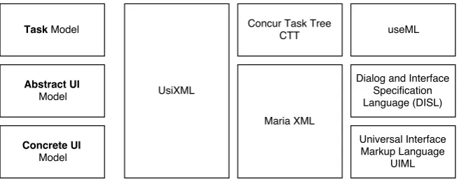
Figure 2.2: Compatible UIDLs with the CRF abstraction levels.
• The USer Interface eXtensible Markup Language (UsiXML) [15] is a XML-based language that is capable of expressing concepts of the first 3 CRF abstraction levels. UsiXML uses graph theory to formalise the language. As a result, an instance of the UsiXML metamodel is a directed, typed graph.
• To capture the semantics of a task, the Concur Task Trees (CTT) no-tation can be used to define a hierarchical task structure with a wide range of (temporal) relationships to constrain the execution order of (sub)tasks [16].
• Maria XML is a general purpose language and able to express both the Abstract User Interface and the Concrete User Interface model [17]. Maria XML differs from UsiXML as is not based on a graph structure, and the metamodel of the concrete user interface is dif-ferent from the UsiXML metamodel as the authors made difdif-ferent design choices.
• Useware Markup Language (useML) [18] was originally developed to support a user-centric development process by providing a lan-guage that allows task modelling and analysis. A use model (task model) consists of platform-independent tasks modelled as so-called use objects in a hierarchical structure. This model is structured as a tree. The leaves represent elementary Use Objects (eUO). A eUO is an atomic interactive task. Available types eUOs are inform, trig-ger, select, enter and change. Like UsiXML and Maria XML, useML (version 2.0) supports temporal relations to relate eUOs.
• Dialog and Interface Specification Language (DISL) [20] is an extended UIML subset designed to model the abstract user interfaces, focusing on supporting adaptation, scalability, reusability, usability for devel-opers (tools) and low resource demands.
Two approaches can be used to define thefinal user interface: the UI can ei-ther be interpreted using a User Interface Management System (UIMS) or compiled using some platform-specific presentation technology. An inter-pretational approach, like MASP [21], DynaMo-AID [22] and Supple [23], uses models to render a UI at runtime. Model interpretation at runtime is usually more suitable for supporting adaptive behaviour than relying on static code artifacts [9]. Another advantage is that UI adaptations can be deployed without recompiling the application. A compiled approach re-lies on code artifacts in a specific presentation language. These artifacts are generated at design-time from the CUI, and adaptive behaviour is limited at runtime. An advantage of this approach is that many platforms can be supported if they support a certain way of defining interactive and presen-tation behaviour in code. A combination of these two approaches is using models defined at design-time to generate code artefacts at runtime. The modelling approach used by the 3-Layer Architecture [24] is an example of this approach. Whereas an interpretational approach seems to have more advantages than a compiled approach, research showed that performance can be an issue in worst-case scenarios [25]. Also, existing tools support is limited and not integrated in a mature IDE.
2.4
Model Transformation Languages and Technologies
In Model-Driven Engineering (MDE), model transformations are used to transform concepts from the source model to the target model. A com-monly used approach is to define a model transformation based on the source and target metamodel. The structure of this technique is shown in Figure 2.3.
According to Object Management Group (OMG) standards, a metamodel is aspecialkind of model that specifies the abstract syntax of a modelling language [27]. A model transformation definition defines the procedure to transform concepts defined in the source metamodel to concepts defined in the target metamodel.
Figure 2.3: A model transformation approach based on the metamodels of both the target and source model as published in [26]
In a top-down approach in Model-Driven Architecture, vertical transfor-mations bridge the implementation gap from specification to an executable system. In a bottom-up approach, a transformation omits details to create abstractions from detailed models. A bottom-up approach can be used in
Reverse Engineeringto inject a model from an existing implementation [29]. Transformations do not necessarily have to be defined to support a single direction, from source to the target model. By defining transformations in both directions, synchronisation between emerging models at different levels of abstraction can be achieved [30].
At the top level, model transformation approaches can be classified in two major categories: model-to-text and model-to-model transformations. We consider programming code as well as other forms of text, such as SQL queries and system configuration files, as model-to-text approaches. In model-to-text transformations, we consider 2 approaches: Visitor-Based and Template-Based approaches:
• Visitor-Based ApproachesA basic approach to model-to-text trans-formations is a visitor-based approach that generates code while travers-ing the inner structure of the source model. An example of this ap-proach is Jamba [31].
When the semantic gap between a the source and target models is large, multiple model-to-model transformations can be defined to bridge this gap. The advantage of using model-to-model transformations is that these transformations tend to be more maintainable, modular, and can be used to debug the transformation then a single transformation. In addition, model-to-model transformations can be used to define horizontal transformations and thereby supports synchronisation between models. We consider 4 ap-proaches to model-to-model transformations:
• Direct-manipulation approachesThese approaches use an API to ac-cess the internal structure of the model. An object-oriented frame-work, like SiTra for Java [34], is an example of this approach. How-ever, features like scheduling and generating traces have to be imple-mented from scratch, making it unsuitable for large complex trans-formation [35].
• Relational approaches A relational approach is declarative, where the main concept is a mathematical relation. The basic idea is to re-late a source to a target element type and define constraints of this relationship. Logic programming can be used to implement the re-lational approach. An example of a rere-lational approach is [36]. Ake-hurst and Kent discusses an approach that captures the essence of mathematical relations in a metamodel.
• Graph-Based approachesGraph transformations can be used in a model-driven approach. These approaches typically operate on typed, attributed, labelled graphs. The main concept of graph transforma-tion is to define a rule consisting of a pattern in the source model and a pattern in the target model. When a pattern in the source model is matched, the model is transformed and replaced by the defined pat-tern in the target model. Conceptually this approach is the same as a metamodel-based transformation as both approaches map concepts from a source to a target model. The metamodel approach, however, does not constrain the structure of the models.
• Structure-Driven ApproachesA structure-driven approach distin-guish 2 phases: in the first phase the hierarchical structure of the tar-get model is created, in the second phase the attributes and references are added.
2.5
Formal Software specification
Since the beginning of Computer Science, formal specifications have played an important role. Whereas behaviour of a system can be specified in natu-ral language, Meyer was among the first to demonstrate the deficiencies of a requirements document written in natural language [37]. Such an infor-mal approach suffers from problems regarding noise, silence, overspecifi-cation, ambiguity, contradictory statements, forward referencing and wish-ful thinking. These problems are hard to solve in natural language alone. Therefore, various research efforts have been devoted to formally specify-ing software systems.
A Formal Specification Languages (FSL) uses mathematical concepts and notations to express the behaviour of a system. Sets, functions and vari-ables can be used to express properties that a system should satisfy. FSLs have been developed to describe what a system must do without speci-fying how it should be done. Sinceambiguity is a key source of errors, as it allows members of the development and validation team to interpret requirements differently, formal specifications are useful as they specify behaviour in an unambiguous manner [38]. Different formal languages exist and each of them uses their own approach. King distinguished for-mal language techniques in two groups: the model-oriented and property-oriented techniques [39].
Property-orientedtechniques describe a system indirectly by stating prop-erties about it. The declaration of such propprop-erties constrains the number of models that satisfy these properties, i.e, the correct programs. Different ap-proaches of property-oriented apap-proaches are Algebraic Methods, Model Logics and Axiomatic Methods.
Model-oriented Instead of constraining the number of models, model-oriented techniques define a model to represent a correct program. In this case, a program is correct if it behaves the same as the specified model [40]. Among different approachestransition-orientedandstate-oriented techniques
use the model-oriented approach.
2.6
Software Verification
Developing a software system is often a process of requirements engineer-ing, interpreting requirements and mapping requirements to functionality, implementing the functionality and testing the result. Whereas software often doesn’t behave as expected from the requirements, verifying soft-ware is often a necessary step. The goal of softsoft-ware verification is to verify if software behaves conform the requirements. We define two major classes in software verification: software testingandformal verification. The former involves the execution of tests to detect defects until one has enough con-fidence that no defects exist. The latter involves theorem-proving, the pro-cess of showing that the program matches the specified function.
2.7
Conclusion
As we have discussed several approaches of User Interface development, the traditional approach shows serious issues regarding consistency and maintenance in the development of user interfaces for different modali-ties and platforms. An approach to tackle this complexity is Model-Driven User Interface Development, which is based on Model-Driven Engineer-ing. This approach tackles the complexity of the development of user interfaces by separating the domain knowledge from the implementation details. The Cameleon Reference Framework implements this MBUID ap-proach and provides a basic apap-proach to structure concepts at different abstraction levels to generate a user interface for different modalities with consistent functionality across platforms. Different modelling languages have been developed that implement the CRF approach. As we require the correctness of the user interface to be verified, we use formal specification techniques.
Chapter 3
Transformation chain
In this chapter we define the general structure of our transformation chain. We give an overview of the involved concepts at each level of abstraction and the main purpose of each transformation. We define the conceptual model of the system and our approach how to achieve correctness.
The transformation chain forms the spine in our approach. As we follow a model-based user interface development approach, the transformation chain consists of models connected with model transformations. These models contain an explicit and mostly declarative description of the pre-sentation and the behaviour of a user interface for an interactive system. Model transformations define the rules to transform concepts from the source model to concepts of the target model. This allows models to be abstracted, when information is omitted with a specific goal, and models to be refined, when information is added.
3.1
Overview
[image:23.595.140.471.586.666.2]We adopt a common approach of the model-driven user interface devel-opment paradigm by structuring the transformation chain in 4 distinctive abstraction levels: the task model, abstract user interface, concrete user in-terface and the final user inin-terface, as discussed in Section 2.2. Each level of abstraction serves its own purpose in this top-down approach. We discuss the relation between these abstraction levels.
Figure 3.1: Models and transformations in the transformation chain
user interfacerefines these tasks into user interface components and be-haviour, abstracted from modality and implementation technology. Only high-level interactions, e.g., presenting information and requiring input from the user are supported with high-level construct elements because of this abstraction. Behaviour is specified as a reaction to specific interac-tion on these elements and can consist of validainterac-tion rules to check if the interaction is conform the specification. For example, if the user presses a button, the specified behaviour can react by executing the next task, as specified in the task model, if and only if the input given by the user is vali-dated. Theconcrete user interfacerefines the abstract user interface and spec-ifies the presentation and behaviour for a certain modality, e.g., a graphi-cal user interface. It refines the low-level construct elements to concrete construct elements, like e.g., textfields and buttons for a graphical user in-terface. Because a concrete user interface model is specific for a modality, dedicated models are defined for each modality. For example, a graphical user interface consists of graphical elements like a menu, forms, textfield and buttons whereas a voice user interface can consist of a dialog. Thefinal user interfaceis implemented in the chosen implementation technology. De-pending on this technology the semantics are captured in a model which can be translated to executable code or interpreted on runtime.
3.2
Conceptual model of the system
The result of the transformation chain consist of an operational user inter-face, an application that enables the user to interact with the system. To define what characteristics of the system we can refer to in the four mod-els, we analyse and define the characteristics of a system that consists of behavioural domain models. From this model we can derive the func-tionality that is at the disposal of the user and can be referred to in the transformation chain.
3.2.1
Concepts
3.2.2
Object Behaviour
We can define the behaviour of an object, that is, the valid operations in a specific state, as a state machine. We can define a state machine as a di-rected graph where nodes denote states and edges denote transitions. A transition defines an atomic action that changes the state. A transition can require arguments that can be constrained by preconditions. Post-conditions define how the attributes of the object are changed and which external objects are manipulated. So, apart from internal state changes, objects can trigger transitions of other objects. The start transition deter-mines the initial state of the state machine. Apart from the initial state, we distinguish end states, which are states with no outgoing transitions. We call the process of objects from initial states reaching end states a life cy-cle. Since objects can have multiple end states, an object can have different life cycles. Figure 3.2 depicts the state machines of two fictive behavioural domain models.
pending
accepted re f used
createTransaction
accept
refuse
(a) Transaction
open
blocked closed
openAccount
open
block withdraw
deposit close
(b) BankAccount
Figure 3.2: State machine of the domain modelSimpleAccountand Transac-tion
3.2.3
Actors
3.2.4
Example: Transaction processing
To illustrate the conceptual model, we look at an example of a system that can transfer money from one account to another, shown in Figure 3.3. We use the defined behaviour of theBankAccountobject and theTransaction ob-ject from Figure 3.2 specified in Listing 3 and 4 respectively, and the speci-fication of the system in Listing 1. From the specispeci-fication of the objects, we generated the set of operations and defined the relevant queries as opera-tions, suffixed with .View(). We have assigned a set of capabilities per user role.
In the example, the system consists of three objects: aTransactionobject, a
Bank account Aobject and aBank account Bobject. The set of capabilities and the state of the object define the valid operations of a user on these objects. To create an instance of a transaction object, the user has to have the op-erationcreateTransactionin his set of capabilities. This initial condition and the fact that the object has to be initialised, determines if the user is able to trigger the transition. To actually invoke the operation, the provided argu-ments of the transition,from,toandamount, has to meet the preconditions the transitioncreateTransaction.
Whereas objects can invoke transitions of linked objects, the preconditions of the linked transitions has to be met. In this example, theAccepttransition triggers theWithdrawandDeposittransitions. Both transitions require the state of the object to beopenand the former requires that the balance should be sufficient.
If all these checks are successful, the transition can be triggered and the state of theTransactionobject changes topending. In this state, the life cycle of a transaction is not completed as the transaction has to be accepted first. Another user, in this example User X, can callAcceptTransaction, as its set of capabilities allows it to do so and theTransactionobject is in the state the transition can be triggered. This changes the state of the object to its final state, which isaccepted.
Objects={Transaction,BankAccountA,BankAccountB}
Actors={UserA,UserX}
Operations={Queries∪Commands}
Commands={Transaction.CreateTransaction(f rom,to,amount),
Transaction.AcceptTransaction()
BankAccount.Withdraw(amount)
BankAccount.Deposit(amount)}
Queries={BankAccount.View()
Transaction.View()}
Capabilities(UserA) ={Transaction.CreateTransaction(f rom:BankAccountA,to,amount)
BankAccountA.View()}
Capabilities(UserX) ={Transaction.AcceptTransaction()}
Listing 1: Definition of theTransactions processingsystem
Capabilities(UserA)∪Capabilities(UserX) =Operations f alse
Listing 2: Formula to verify if the total set of capabilities comprises the set of operations
of a transaction, the object can be considered as complete when the trans-action is accepted. A bank account is completed when the bank account is closed. In these states no outgoing transitions can be triggered. If we define the capabilities of each user, we can verify if the total set of capabil-ities covers a complete life cycle: does the set of capabilcapabil-ities consist of all operations needed to execute a path from initiating an object towards all end states? This property does not necessary assesses if the user interface is correct. Whereas multiple applications can invoke transitions, and not necessarily only the user interface, this property does not always have to hold. It enables the modeller to assess if he included the necessary oper-ations. We can check this property for each user, and the life cycle of an object.
1 event withdraw[] (accountNumber: IBAN, amount : Money) {
2 preconditions {
3 amount >= balance;
4 }
5 postconditions {
6 new this.balance == this.balance’ - amount;
7 new this.accountNumber == accountNumber;
8 }
9 }
10
11 event deposit[] (accountNumber: IBAN, amount : Money) { 12 preconditions {
13 }
14 postconditions {
15 new this.balance == this.balance’ + amount; 16 new this.accountNumber == accountNumber;
17 }
18 }
Listing 3: Specification of withdraw and deposit events as defined for the BankAccount object
1 event CreateTransaction[] (from: IBAN, to: IBAN, amount : Money) { 2 preconditions {
3 amount >= EUR 0.00;
4 }
5 postconditions { 6
7 }
8 }
9
10 event AcceptTransaction[] () {
11 preconditions {
12 }
13 postconditions {
14 from.withdraw(amount);
15 to.deposit(amount);
16 }
17 }
Transaction
Object
BankAccount A
Object 2. Withdraw
BankAccount B
Object
2. Deposit
System 1. CreateTransaction
User A
Actore
User X
Actore
[image:29.595.207.404.332.509.2]2. AcceptTransaction
3.3
Correctness by Construction
We require the output of the transformation chain, the implementation, to be functionally correct with respect to the input of the transformation chain, the task model. The implementation is correct if it behaves as ex-pected. Since the implementation is often a human task, the introduction of errors is often unavoidable. Therefore, testing is a necessary task to val-idate if the implementation conform to the requirements and if no errors have been introduced. Two issues can arise here. If developers, business analysts, testers and other stakeholders interpreted the requirements dif-ferently, qualifying the software as correct is not possible. The other issue is that testing is often an engineering task. The more effort is put into this task, the more errors can be revealed. However, as a result, there can be no guarantee that no errors exist in the system-under-test as more effort could lead to revealing more errors. Our approach to these issues is es-sentially different than common development practises. We seek to create an implementation that is initially correct, by applying the method of Cor-rectness by Construction (CbyC) as described by Hall and Chapman [38]. CbyC defines two fundamental principles to software engineering -to make it difficult to introduce defects in the first place, and to detect and remove any de-fects that do occur as early as possible after introduction[42]. By integrating the building blocks of CbyC into the structure of the transformation chain, the generated implementation is, in theory, correct.
3.3.1
Building blocks of Correctness by Construction
This may sound ambitious or unrealistic to be used in practise. However, with the right building blocks we can give certain guarantees to the imple-mentation. In the transformation chain we adopted the following building blocks.
Unambiguous notations
Strong Validation
Ideally, for every human involvement in the transformation chain, we want to validate the properties of the defined artefact at design-time to avoid the introduction of errors. This principle is essential in our approach. We want to detect errors when they are introduced. Since formal methods can provide rigorous notations, we can use formal methods to validate the correctness of the defined artefact. In our approach the task model is based on an Operation Petri-net (OPN). This allows us to validate the task model by simulation and by checking correctness properties, such as: does it express all the workflows that the modeller envisioned, and is the specification consistent?
Correctness preserving transformations
Since we defined the use of sound notations for the task model, and the existence of validation tools to validate the correctness of this model, we defined transformations that preserve correctness. We shift the focus from creating an implementation by hand to generating an implementation for every instance of the task model, we achieve correct implementations by validating the transformations. We define properties that should be pre-served. If these properties are preserved during the entirety of the transfor-mation chain, including the generated implementation, we conclude that the transformation chain produces a correct user interface with respect to the defined properties.
Avoidance of Repetition
The structure of the transformation chain facilitates the reuse of the models at different abstraction levels. Therefore, we can use existing models to create a user interface for a new platform. Also, since domain models are defined in separate models, and we define references to these models, we avoid redefining domain model behaviour.
Tracebility
3.4
Integration of new platforms and devices
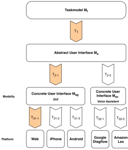
Because of the structure of the transformation chain, models can be reused and interchanged to generate a user interface for a different modality and implementation technology. To illustrate this, the concept of model reuse is depicted in Figure 3.4.
Taskmodel Mt
Abstract User Interface Ma
T1
Concrete User Interface Mag
GUI
T2-1
Concrete User Interface Mav
Voice Assistent
T2-2
Android iPhone
Web
T31-1 T31-2 T31-3
Amazon Lex Google Diagflow
T32-1 T32-2
[image:32.595.198.416.211.467.2]Platform Modality
Figure 3.4: Models and transformations for different platforms and modal-ities
From the task model, we can generate withT1an abstract user interface.
From the abstract user interface, we can transform the abstract objects to concrete objects. While the concrete objects are expressed for a certain modality, we can define for each modality a separate model and transfor-mation. For example, we define a model transformationT2-1for a concrete
user interface model of a graphical user interfaceMag. The same applies
for a concrete user interface for a voice assistant.
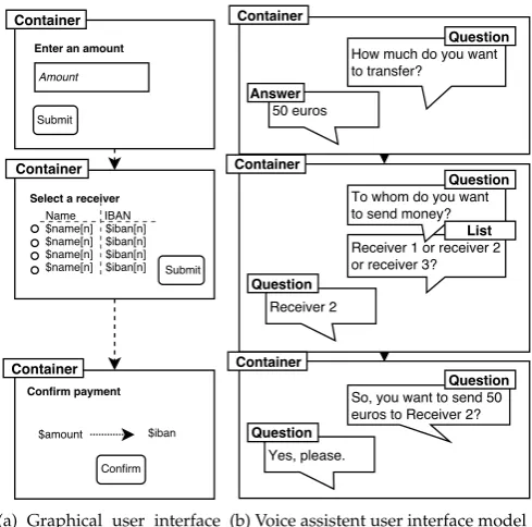
From the abstract user interface, we define different branches for different modalities. An example for a graphical user interface (GUI) is illustrated in Figure 3.6a and a voice assistant user interface (VUI) is illustrated in Figure 3.6b. Both models define an interaction with the user but use dif-ferent concepts as interaction objects. In the GUI model, the user interface is defined as a Container that contains text fields for numerical and textual input, a button to confirm the input and a checkbox list to select an item. In the VUI model, the objects are limited to a dialog with questions and an-swers. We define dedicated metamodels for both modalities and defined these in Section 5.
3.5
Conclusion
Figure 3.5: The workflowCreate a transaction in the task model and the abstract user interface model
(a) Graphical user interface model
(b) Voice assistent user interface model
Chapter 4
Task model
In this chapter we describe the design choices for the task model with the design guidelines from the previous section. This model forms the input for the transfor-mation chain.
4.1
Overview
The task model forms the highest level of abstraction in our transformation chain. It defines the workflow, as sequence of tasks, from a user perspective and can be used to analyse the interaction between user and system and as the source to generate the abstract user interface from. The goal of a task model specification is to define which tasks have to be performed to reach a certain (business) goal.
In our solution, business analysts with a technical background should be able to define the specification of the resulting user interface. Therefore, task modelling should be simple enough to understand and to be carried out. We also require a rigorous notation such that we can validate the speci-fication at design-time and generate an operational user interface. Whereas such a notation involves complexity related to task ordering, interaction with system services and internal state management, the challenge is to balance the amount of complexity incorporated in the task model. In addi-tion, we require the task model to fit in the MBUID process as we defined in Chapter 3. Consequently, the task model should not contain a large se-mantic gap with the other abstraction levels. As our goal is not to define a new approach to task modelling (since this does not fall within the scope of this research), we analysed the capabilities of the existing task modelling approaches. As a result, we defined a task modelling method that uses techniques from different approaches such that the complexity of the task model can be tackled step by step, and can be used as a source to generate an operational user interface.
Workflows
Structural Model
Interaction Markings
Dynamic Model
T
[image:36.595.211.403.128.326.2]T1
+
Task modelFigure 4.1: The tasks in the structural model annotated with an interaction class forms the input for the transformation to the dynamic model.
a model transformation generates a specification that definesdynamic tasks
which specifies the input and output flow of data and events in thedynamic model(Section 4.5). The approach we used is depicted in Figure4.1.
4.2
Task modelling techniques
In the field of User-Centered Design (UCD), task modelling and analy-sis have been widely accepted as one fundamental way to ensure user-centered design [43] and to improve the understanding of how a user may interact with a user interface. A task model is often defined as a set of interactive tasks performed by either the user or the system, or by both, through the user interface. We discuss the main methods in task modelling and analysis involved in user interface development.
4.2.1
Hierarchical Task Analysis
4.2.2
GOMS
The GOMS method describes and analyses how a user should perform their tasks in terms of Goals, Operators, Methods and Selection rules. Since the introduction, different forms of GOMS have been developed, each fo-cusing on a different notation with different analysis goals. With the origi-nal GOMS model as the root of the family, KLM-GOMS [45], CMN-GOMS [45], Natural-GOMS-Language (NGOMSL) [46] and CPM-GOMS [47] are derived from this model. The Keystroke-Level Model (KLM) estimates the execution time for a task based on the actions the user must perform in terms of primitive operators. The CMN-GOMS defines a strict hierar-chy of tasks with the goal to predict the operator sequence and the exe-cution time. Natural-GOMS-Language (NGOMSL) defines a task model with task written in natural language with the goal to predict the the oper-ator sequence, execution time, and time to learn the methods. Cognitive-Perceptual-Motor GOMS (CPM-GOMS), just as the other GOMS models, predicts the execution time. However, unlike the other models, the opera-tors are defined as perceptual, cognitive and motor acts.
4.2.3
Groupware
Groupware Task analysis (GTA) is a technique to model the complexity of tasks in a cooperative environment [48]. Different to other task modelling methods, GTA focuses on people, work and the situation.
4.2.4
ConcurTaskTree
ConcurTaskTree (CTT) is a descriptive notation for defining task model specifications for interactive applications [49]. CTT has a formal definition of the temporal operators which originates from process algebra. The task model, defined as a recursive tree, consists of a root task decomposed of subtasks related with temporal operators. The definition of a task is de-fined as an action that manipulates an object. Tasks can be assigned to specific platforms to support different tasks for different target platforms.
4.2.5
MAD
4.2.6
Task Oriented Object Design
Task Oriented Object Design (TOOD) defines tasks as objects with an input transition and an output transition [51]. A task can only be performed when the input conditions, such as the availability of data, are met. Tasks that are triggered by events can be decomposed in subtasks.
While HTA, GOMS and MAD are restricted to decomposing tasks into sub-tasks related by temporal operators, we consider these approaches not as expressive as Groupware, CTT and TOOD. While TOOD uses mathemati-cal functions to define when tasks has to be performed, this approach tends to become complex. However, since TOOD can be simulated using Petri-nets, strong validation can be achieved.
CTT on the other hand, is not as complex as TOOD, and has been widely recognised as a notation for task modelling. Existing MBUID approaches, such as AMBOSS [52], useML [53], taskMOD [54], UsiXML [15], MANTRA [55] and THERESA [56], are similar to CTT. This comes with the price that only the temporal constructors integrated in CTT are formalised using tem-poral algebra. The interaction with domain models is limited to defining access to attributes of domain models and if the user has to manipulate or to perceive the attribute. Whereas this approach is sufficient for a wide range of use cases, we define a more rigorous approach that defines the interaction that has to be carried out in a task. As a result, we are able to validate if the generated implementation enables the user or system to carry out this interaction.
4.3
Workflows in the Structural model
4.3.1
Formal description
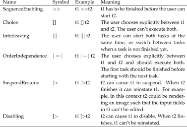
The structural task model is structured as an recursive tree with a single distinguishable root node as the top node with the direction of the vertices going downwards. Each task can contain an ordered list of subtasks as children. Temporal constructors are used to define the possible execution paths between two subtasks at the same level. Tasks can only have a tem-poral constructor with the previous or next task in the list. The operational semantics of these constructors are defined in Table 4.1. The amount of subtasks of a task is not bound to any limit.
Name Symbol Example Meaning
SequenceEnabling >> t1>>t2 t1 has to be finished before the user can start t2.
Choice [] t1 [] t2 The user chooses explicitly between t1 and t2. The user can’t execute both. Interleaving ||| t1|||t2 The user can start both tasks at the
same time, or switch between tasks when a task is not finished yet.
OrderIndependence |=| t1| − |t2 The user chooses explicitly between t1 and t2 and should execute both. The first task should be finished before starting with the next task.
SuspendResume |> t1|>t2 t2 can cause t1 to suspend. When t2 finishes it can reinstate t1. For exam-ple, in this context t2 could be render-ing an image such that the input fields in t1 can’t be edited.
Disabling [> t1 [>t2 t2 can cause t1 to disable. When t2 fin-ishes, t1 can’t be reinstated.
Table 4.1: Temporal constructors with their symbols and meaning as de-fined by CTT [49]
t0
t1 t2
t4 t5
t3 >> >>
[]
(a)
t0
[image:39.595.115.493.277.533.2]t1 >> t4 [] t5 >> t3 (b)
4.3.2
Operational Semantics
The CTT notation allows one to define workflows of the task model suc-cinctly. However, defining the temporal constructors that should define the order of tasks is not sufficient to obtain the supported workflows in all cases. For example, if we look at Figure 4.2b, it can be unclear which workflows are supported. Therefore, we need to define a solution for this problem. A typical solution would be to define precedence and associa-tivity conventions among operators to resolve ambiguity [57]. However, we would argue that the hierarchical structure gives the user enough pos-sibilities to define such a priority among operators by defining dedicated subtrees. In addition, this would increase the complexity of the task model and that is what we want to avoid. The simplest approach would be to de-fine no precedence and left associativity among operators. In that case, the possible execution traces of the task model can be expressed in the follow-ing formula in Listfollow-ing 5. The original approach of CTT defines a priority amongst operators, as defined in Listing 6, which results in a different for-mula, as listed in Listing 7.
t0 ⇐⇒t1>>(t4[](t5>>t3))
t0 ⇐⇒t1∨(t4∧(t5∨t3))
Listing 5: Formula to evaluate if t0 is finished when operators are left-associative without precedence
Choice [ ]
Interleaving |||
Disabling [>
SuspendResume |>
OrderIndependence |=|
SequenceEnablingIn f o [ ]>>
SequenceEnabling >>
Listing 6: Precedence amongst operators according to the CTT notation
t0 ⇐⇒t1>>(t4[]t5)>>t3
t0 ⇐⇒t1∧(t4∨t5)∧t3
Both solutions are examined, and both solutions should resolve ambiguity. Further research is needed to verify if our concerns about increased com-plexity are legitimate. A different solution is to prohibit the use of different temporal constructors on the same level. For this solution we would re-quire clear rules to define what combination of constructors are allowed. This solution however, would lower the expressiveness of the language, and the modeller is required to understand and apply these rules.
For the rest of this research we choose the simplest approach of defining no precedence and left-associativity among operators. When the supported workflows of the task model are not clear from its visual presentation, as in Figure 4.2b, the user can examine the generated execution traces to get the necessary feedback. In Appendix B, we defined a procedure to obtain these execution traces.
4.4
Interaction Specification Markings
The structural task model defines workflows that the user interface has to support. The intention of the task, however, is only captured in its name. Without a definition of the required interaction, we cannot generate an im-plementation. Therefore, interaction classes are defined which can be used to annotate tasks to further specify the interaction carried out in a specific task. The abstraction tasks in the structural task model decompose task into smaller non-decomposable interaction tasks. It is these interaction tasks which need to be annotated with a type of interaction. It is important to understand that the function of the abstraction tasks in the structural model is to decompose tasks in smaller subtasks. The leaves of the tree contain the actual interaction. We present an example, illustrated in Fig-ure 4.3, to explain how these classes can be used to specify the interaction carried out in the tasks. In this model, theCreate a Transactionworkflows defines a process that enables the user to enter the required information for transferring money. Tasks labeled with a()symbol denote an interaction task, and thus these tasks need to be annotated. We discuss the different types of interaction that can be assigned to these tasks.
4.4.1
User Interaction
Create a Transaction
Specify amount() Specify receiver
Select from address book
Fetch addresses() Select from addresses()
Specify account number()
Review transaction() Confirm transaction()
>> >> >>
>>
[image:42.595.69.542.116.239.2][ ]
Figure 4.3: Example of the task modelCreate a Transaction
classes: execute, select, dataInput, change and inform. These classes define interactions of user tasks in a platform independent way and correspond to the definition of a user. We adopted different terms for these interac-tion classes, which correspond with the user perspective of the task model: trigger, select, generate, manipulate and observe, respectively.
User Interaction
Trigger Select Manipulate
Observe Input
Figure 4.4: Overview of user interaction classes
To mark the tasks with the appropriate interaction class, insight into the type of input the system expects is required. For example, the taskSpecify receiver, in Figure 4.3, can be specified as a task that requires the user to select a receiver from a list, fetched by the system, or by entering an ac-count number. Whereas both approaches result into a value that defines the receiver, the former requires a user toselectan account, and the latter requiresgeneratinga value that correspond to the account number format. In another scenario, the receiver may be pre-defined and the user has to verify if the value is correct. In that case, the user may want tomanipulate
the value. The example in Figure 4.3, adopts the first two approaches and annotates theSelect from addressestask with theselectinteraction class. The
[image:42.595.212.395.378.532.2]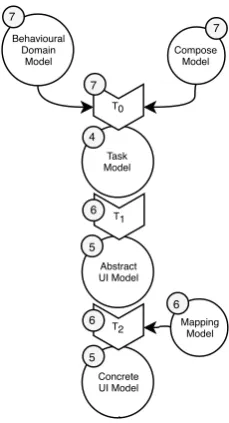
![Figure 2.3: A model transformation approach based on the metamodels ofboth the target and source model as published in [26]](https://thumb-us.123doks.com/thumbv2/123dok_us/9715930.472580/19.595.178.427.121.314/figure-transformation-approach-metamodels-ofboth-target-source-published.webp)