Dr. L. (Luís) Ferreira Pires
2018
NOV
22
Dr. ir. M.(Maurice) van Keulen
Examination committee
USING
USER WORKFLOW ANALYSIS
TO CREATE INSIGHTS IN
CONTENT-INTENSIVE APPLICATIONS
UNIVERSITY OF TWENTE.
Computer Science
M.C. (Marlène) Hol s1317210
3
Preface
This thesis completes my exciting time at the University of Twente. It has been an amazing journey from starting here as a freshman in 2012, to becoming an alumnus now. For me, the University of Twente will always be a special place. It is the place where I learnt so many interesting things, developed so many different skills, where I founded my company Mobina, where I found love, made great friends and so much more. But all good things come to an end. However, this I not a sad ending. I’m looking forward to putting all my time and energy in Mobina, and hopefully to make it the company we all believe it can be.
I would like to take this opportunity to thank several people. First, I would like to thank my supervisors Maurice van Keulen and Luís Ferreira Pires for their valuable feedback on my thesis. I would like to thank Maurice for always giving me the opportunity to explore the topics I was really interested in and making it possible to combine this with Mobina. I would like to thank Luís for always being critical, not only at my design and implementation, but also by giving me valuable textual feedback.
Next, I would like to thank everybody at Mobina, with a special thanks to some of them. First, I would like to thank Jasper Boot, René Hol, Valerija Olsevska, Jochem Verburg, and Hans Wortmann for participating in the data collection. I would also like to thank René, Valerija, and Jochem for using their expertise in the Mobina content in the validation. Additionally, I want to thank Jasper for his technical support when we developed the logging framework necessary to perform this project. Because of his background in Business Information Technology, Jochem also proved himself valuable as company supervisor. I would like to thank him for all his feedback on my project, both content-wise and textual. Finally, I would like to thank René and Jochem for giving me all the freedom to perform this project and giving me the opportunity to steer this project in a direction that I deemed not only useful for Mobina, but that is also aligned with my personal interest and study background. Their unconditional trust in the project and the road I was taking greatly motivated me.
Finally, I would like to thank my friends and family for their (moral) support during my thesis. I could not have done it without them. I would like to thank Meike Nauta and Caspar
5
Abstract
Traditional methods for evaluating software are often less suitable for content-intensive applications because they are not always able to track the steps of a user across the entire application, because they are less suitable for continuous improvement due to their lack of scalability, and because the observed behavior might be different from reality. We introduce user workflow analysis as a solution to help content and software developers (user workflow analyzers) of content-intensive applications (referred to as System Under Analysis or SUA) to gain additional insights in the usage of the application that can’t be acquired through traditional methods.
We present a design and prototype implementation of the User Workflow Analysis Tool (UWAT). This tool successfully implements user workflow analysis by combining the strength of Process Mining (PM) in extracting patterns from event log data and the strength of Model-Driven Engineering (MDE) in standardized and automatic transformations. This research shows that MDE, due to its standardization power, can mitigate the shortcoming of PM that it is often left up to user to configure the plugins and interpret the results. In this design, only the implementer of the UWAT needs to understand the PM configuration and results, and all other user workflow analyzers can benefit from this in a standardized, automated and user-friendly way. No references were found that this combination was used for this purpose before.
The UWAT itself consists of five metamodels: SUA metamodel, plugin specification metamodel, user specification metamodel, Process Mining metamodel, and result
metamodel. All metamodels are set-up as generic as possible, so they can easily be used for multiple SUAs. Four transformations are introduced: to create the SUA model instance, to translate the input of the user workflow analyzer to a user specification model instance and the instructions for PM, to process the result of PM to useful results for the user workflow analyzers based on the user specification, and finally to translate the result model instance to the output data that can be used for visualization of the results. The PM execution happens externally, but the UWAT handles the call to these external plugins. In this way, users of the UWAT can benefit from external knowledge in an area that is rapidly evolving. The visualization for the user workflow analyzers is separated from the UWAT, so the SUA implementer has a lot of flexibility in how to present the results.
For the prototype implementation and validation, a case study is done for a content-intensive application, Mobina. The Mobina team created their own modelling technique for the
complex content. They are expected to benefit from user workflow analysis to validate the modelling technique and the interface supporting this. The design was validated using two types of expert opinion: user validation and technical review. Potential user workflow analyzers were interviewed to identify the added value of user workflow analysis and to assess the requirements relevant for user workflow analyzers. The technical review is a critical review of this design, and where necessary its implementation, to validate to what extent the requirements of the architecture were fulfilled.
6 This research successfully showed how by combining PM and MDE, different user workflow analyzers can benefit from analyses in a reusable, scalable and user-friendly way. This combination of PM and MDE led to a user-friendly solution where the user workflow
analyzers are not bothered with the implementation details. New functionality and analyses can easily be added which makes the solution flexible and scalable. Due to the generic setup of the metamodels, most of the metamodels can be reused for different SUAs. Some parts of the transformations need to be implemented for each SUA separately, so the SUA implementer has a lot of flexibility and can implement all desired analyses. As soon as the necessary PM support is there, this solution can also be fully automated.
7
Table of Contents
Preface ... 3
Abstract... 5
Table of Contents ... 7
Glossary... 10
1 Introduction ... 11
1.1 Problem statement ... 11
1.2 Research questions ... 12
1.3 Research design ... 13
1.3.1 Scope ... 13
1.3.2 Approach ... 14
1.4 Report structure ... 14
2 Background and related work... 15
2.1 Model-Driven Engineering (MDE) ... 15
2.1.1 Concepts ... 15
2.1.2 Use cases ... 17
2.1.3 MDE in practice ... 17
2.2 Process Mining (PM) ... 18
2.2.1 Techniques ... 18
2.2.2 PM in software engineering ... 18
2.3 Combining PM and MDE... 19
3 Case study: Mobina ... 20
3.1 Mobina application ... 20
3.2 Relevance ... 20
3.3 Mobina components ... 21
4 Solution ... 24
4.1 Requirements ... 24
4.1.1 Functional requirements ... 24
4.1.2 Non-functional requirements ... 24
4.1.3 Domain requirements ... 25
4.2 High-level architecture ... 25
4.3 Techniques ... 26
5 (Meta)models and transformations ... 27
5.1 Overview ... 27
5.2 Metamodels ... 27
5.2.1 SUA metamodel ... 27
5.2.2 Plugin specification metamodel ... 29
5.2.3 User specification metamodel ... 30
8
5.2.5 Result metamodel ... 33
5.3 Transformations ... 35
5.3.1 Data-to-SUA transformation ... 35
5.3.2 Preparation-to-specification transformation ... 35
5.3.3 Process-to-result transformation ... 36
5.3.4 Result-to-dashboard transformation ... 36
6 Implementation prototype ... 38
6.1 Scope ... 38
6.2 Tools ... 38
6.3 Preparation ... 39
6.3.1 Preparing the event log ... 39
6.3.2 Data-to-SUA ... 40
6.4 User preparation ... 41
6.5 UWAT and PM implementation ... 42
6.5.1 Preparation-to-specification ... 43
6.5.2 Process input ... 45
6.5.3 Process output ... 45
6.5.4 Process-to-result ... 47
6.5.5 Result-to-dashboard ... 48
6.6 Result dashboard ... 49
7 SUA guidelines ... 51
7.1 Business objectives ... 51
7.1.1 Determining the business objectives ... 51
7.1.2 Case study ... 51
7.2 Logging of the software ... 52
7.2.1 Logging data ... 52
7.2.2 Logging framework ... 52
7.2.3 Case study ... 53
7.3 Data generation ... 55
7.3.1 Experiment scoping ... 56
7.3.2 Experiment planning ... 56
7.3.3 Experiment operation ... 57
7.3.4 Presentation & package ... 58
7.3.5 Case study ... 58
8 Validation ... 60
8.1 Approach ... 60
8.1.1 User validation ... 60
8.1.2 Technical review ... 61
9
8.2.1 Functional requirements ... 61
8.2.2 Non-functional requirements ... 63
8.2.3 Domain requirements ... 66
8.2.4 Usefulness of user workflow analysis ... 66
8.3 Summary ... 66
9 Discussion ... 68
9.1 Added value user workflow analysis ... 68
9.2 Setup of the UWAT ... 68
9.2.1 Combination of PM and MDE ... 68
9.2.2 Reusability ... 69
9.2.3 Separation visualization and UWAT ... 70
9.2.4 User friendliness ... 71
9.2.5 Scalability ... 71
9.3 Implications of proof of concept... 72
9.4 Validity ... 72
10 Conclusion ... 74
10.1 Summary ... 74
10.2 Implications and recommendations for content-intensive applications ... 75
10.3 Scientific contributions and future research ... 76
References ... 78
Appendix A. Business objectives Mobina ... 80
10
Glossary
Data-to-SUA transformation Transformation that translates the SUA data to an
instance of the SUA metamodel.
Mobina The content-intensive application user for the case
study.
Model-Driven Engineering (MDE)
Methodology that is used to implement the UWAT.
Plugin specification (meta)model
(Meta)model that contains the specification of a PM plugin.
Preparation-to-specification transformation
Transformation to translate the specification of the user in a preparation interface to an instance of the user specification metamodel.
Process Mining (PM) Technique that is used to extract the patterns from the
event log data of the SUA.
Process Mining (meta)model (Meta)model that contains the outcomes of the PM
plugins of the user specification.
Process-to-result transformation
Transformation that translates a PM model, a user specification model, and a SUA model to an instance of the result metamodel.
Reference model Content element of the case study Mobina.
Result (meta)model (Meta)models that contains the results of the analyses.
Result-to-dashboard transformation
Transformation that translates a result model to a textual representation that can be used for visualization.
SUA data Data about the SUA that is relevant for the user
workflow analysis.
SUA (meta)model (Meta)model that contains all the specifics of the SUA
SUA owner The person responsible for implementing the UWAT in
the SUA development process.
System Under Analysis (SUA) The content-intensive application that is being
analyzed.
User specification (meta)model
(Meta)model that contains the specification of the user workflow analyzer on what to analyze.
User workflow The sequence of interactions the user has with the
entire artifact.
User workflow analyzer The user of the UWAT. This includes the content and
software developers of the SUA.
User Workflow Analysis Tool (UWAT)
11
1 Introduction
This chapter introduces this thesis. Firstly, the problem statement is introduced with a strong focus on content-intensive applications. This is followed up by the introduction of the
research questions. Then, the research design is presented including the scope of this thesis. Finally, the rest of the report is introduced.
1.1 Problem statement
Anyone who develops a software product has the goal to develop a product that optimally supports the user. If the user has the feeling that he/she can use the software effectively, this will lead to higher user satisfaction. It is therefore widely accepted that the user should play an important role in software development processes to make sure the user can get the most out of the developed software [1]–[3].
This is especially the case for content-intensive applications, which are applications
containing (complex) content and where the software is designed and developed to support this content. In this case, the structure of the software and its content, i.e., the way the software and its content are designed and modelled, determines a large part of the user satisfaction. The content needs to be modelled and structured so that the user can always understand the software and find its way through it.
Currently, off-the-shelf software is often developed based on the experience and expectations of the company who develops the software. The user often does not (systematically) participate in the software development process, and when the user is involved, often more traditional methods focusing on the graphical user interface (e.g., whether the user can easily save the progress on the screen) or using statistical facts about the software (e.g., the number of errors) are used to test software usability [4], [5]. Involving the user through these traditional methods already improves the quality of software
significantly and will improve system usage [6], [7]. However, these methods are often less usable nor enough for content-intensive applications for three reasons:
1. These methods are often more focused on details and the graphical user interface. This makes them unsuitable for determining whether the software and its content are structured correctly and, more importantly, it makes them unsuitable to discover the different steps or tasks the user is taking across the entire application. Especially in content-intensive applications, the actions that are not directly related to the user interface and are not necessarily in the same view are crucial to determine the next steps and improvements in the software and its content.
2. These traditional methods are often used for the initial design, and not for
continuously improving the software. Involving the users in the entire development process is often not scalable, especially in the case of user testing where the actual person and its actions must be tracked. Every time the user is involved leads to additional expenses, which adds a lot of extra costs to the software development process [8], [9]. Consequently, this also often means that only a small part of the (potential) users are involved instead of the entire target population. Due to this poor scalability, these methods are less suitable for continuously improving applications. 3. In the case of content-intensive applications, learning from the actual behavior is
12 In the past few years, a new approach for evaluating software has been developed, namely user workflow analysis. In user workflow analysis the log data is evaluated which includes all the different interactions the user has with the entire artifact, in this case the software
application. These interactions can be to achieve a specific goal, e.g., to reach a certain state or perform a specific action, or simply a sequence of steps with no immediate goal. User workflow analysis provides the opportunity to capture the actual process automatically and to see how this process relates to the expected or desired process. Emerging
techniques like data mining, machine learning, and process mining enable and improve this approach to analysis.
User workflow analysis can therefore be very useful for content-intensive applications, especially since it seems to fill the gaps left by more traditional methods. Firstly, it does not focus on the details but on how the user interacts with the application. Secondly, it is capable of capturing behavior across the entire application and not just a small part of the
application. Therefore, it is also suitable for analyzing not only functionality, but also the content that could highly influence each interaction. Additionally, since it tracks actual behavior the results are not influenced and there is no artificial setting. Finally, it has the potential to become fully automated which would make it scalable. Because of these reasons, user workflow analysis is expected to help identify where the predicted workflow differs from the discovered workflow and whether the content and the software are properly structured.
Several techniques are available that can (partially) implement user workflow analysis. Based on the goals of the analysis, and the interest and experience of the developer, everyone should decide for themselves which techniques to use. In this research, a combination of two techniques is chosen to implement user workflow analysis: Process Mining (PM) and Model-Driven Engineering (MDE). These techniques have the potential to create a solution which can be applied to all content-intensive applications in a generic way. Additionally, we expect these techniques can be fully automated, which makes them
scalable and suitable for continuously improving software. Finally, we expect that these techniques help present the results in ways that anyone can analyze the results, not only the software developers. Due to these reasons and previous experience of the researchers, these techniques are selected for this research.
1.2 Research questions
In this research, we investigate whether user workflow analysis can indeed give additional insights in content-intensive applications that are not possible with traditional methods. This leads to our first main research question:
1. How can user workflow analysis help content and software developers of content-intensive applications gain additional insights in the content and the software?
As mentioned before, user workflow analysis can be implemented in many ways. In this research, we inspect the implementation with PM and MDE. The combination of these two techniques has not been extensively researched yet. This leads to our second main research question:
2. How can Process Mining and Model-Driven Engineering be used in combination to implement user workflow analysis?
13 a. To what degree can this combination be used to implement user workflow analysis in
a generic way to make it usable for all content-intensive applications?
b. To what degree can this combination be used to implement user workflow analysis in a scalable way?
c. To what degree can this combination be used to implement user workflow analysis in a way that content and software developers can use the results without needing to know the details of the implementation?
1.3 Research design
In this research, an architecture to perform user workflow analysis with PM and MDE has been designed. A prototype of the tool has been implemented and validated with a case study.
1.3.1 Scope
Figure 1 shows how the tool designed in this research is integrated in the development of content-intensive applications. The research artifact is the User Workflow Analysis Tool
(UWAT). Content and software developers of content-intensive applications will use this tool to analyze the user workflow of content-intensive applications: user workflow analyzers. The content-intensive application is the System Under Analysis (SUA). The SUA is not part of the UWAT, merely the object that is being analyzed. The SUA owner is responsible for
implementing the architecture in the SUA development process.
[image:13.595.79.539.419.638.2]The SUA user interacts with the SUA. These interactions are logged in the log data and are the input for the UWAT, together with other relevant information of the SUA, namely the SUA data. Based on these data, the UWAT can generate relevant results for the user workflow analyzer, which can then use these results to decide whether to improve the SUA.
Figure 1 Role of the UWAT
14
1.3.2 Approach
The research consists of the following three phases:
1. Design. In this phase, the requirements of the architecture have been defined, which have been used to design the architecture. The design includes the definition of the (meta)models and transformations as well as the integration of PM and MDE. 2. Implementation. In this phase, the architecture has been implemented. This
implementation has been used for the validation. The implementation is based on a case study using a content-intensive application.
3. Validation. In this phase, the architecture has been validated, and the research questions have been answered. The user workflow analyzers of the case study were involved in the validation.
As mentioned before, the architecture needs log data and actual information about the SUA. Furthermore, the user workflow analyzers should know beforehand what they want to
analyze, since this defines what the results should be. Therefore, before implementing the UWAT the business objectives should be clear and data collection should be aligned to support these business objectives. Although they are not important for the UWAT
architecture, these are important aspects for the case study and are therefore described in this thesis.
1.4 Report structure
The thesis is further structured as follows. Chapter 2 presents background on the selected techniques and the related work. Chapter 3 presents the case study that is used as an example and for validation. The SUA in this case study is the content-intensive application Mobina.
Chapter 4 gives the requirements and the UWAT high-level architecture. The UWAT is mainly implemented using MDE. Chapter 5 presents the metamodels and transformations of the MDE implementation. Chapter 6 describes the implementation of the prototype. The prototype is implemented for the case study and was used for the validation of the design. Chapter 7 discusses the preparations each SUA owner should do. The implementation for the case study is also discussed.
15
2 Background and related work
This chapter presents background information on MDE and PM. This chapter also
investigates and discusses the application of MDE in practice and PM for extracting the user workflow. Additionally, existing research about the combination of both techniques is
discussed.
2.1 Model-Driven Engineering (MDE)
This section explains what MDE is and the concepts behind it. It also describes the cases in which MDE is useful. Last, it presents the strengths and risks of using MDE in practice.
2.1.1 Concepts
The foundation of the Model-Driven Engineering (MDE) methodology is the Model-Driven Architecture (MDA) initiative of the OMG group1. The motivation of this initiative has been to
separate the specification of system functionality from the implementation of that
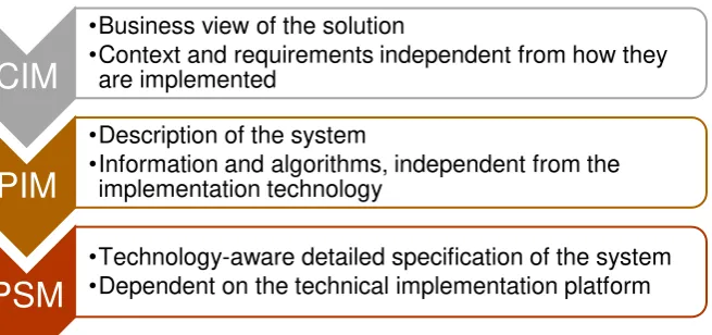
[image:15.595.85.413.336.490.2]functionality on a specific technology platform [10], [11]. This led to the distinction of Platform Independent Models (PIMs) and Platform Specific Models (PSM). MDA presents three levels of modeling abstraction: PSM, PIM, and Computation Independent Models (CIM) [12], [13]. Figure 2 depicts these levels.
Figure 2 Three levels of modelling abstraction
There are several reasons to separate these levels. Firstly, by abstracting from a specific platform, the correctness of the model can be validated more easily. Secondly, it is easier to produce implementations on different platforms, while having the same structure and
behavior. This also means technology can be changed without having to redevelop and redesign the entire application. Finally, it improves the integration and interoperability across systems because they can be defined in platform-independent terms [10].
MDA is just a framework, so it does not incorporate a specific development process or methodology. The broader term Model-Driven Engineering (MDE) embodies a lot of the MDA technologies but combines this with a software development process. MDE employs the general concepts of modelling, independent of a particular standard.
Models are the foundation of MDE. In MDE a metamodel defines the abstract syntax of a language that allows models to be defined. This could lead to an unlimited level of models. Figure 3 shows the four layers of metamodeling that are often used with MDE [12].
1 http://www.omg.org/mda/
CIM
•Business view of the solution
•Context and requirements independent from how they are implemented
PIM
•Description of the system
•Information and algorithms, independent from the implementation technology
PSM
•Technology-aware detailed specification of the system
16
Figure 3 Four layers of metamodeling often used in MDE
[image:16.595.72.182.71.239.2]Model transformations are an important technique in MDE. The idea is that one can automatically generate other models or text based on an input model and the metamodel definitions. A developer can manually write these transformations, but they can also be produced automatically using some higher-level mapping rules between models. When using the latter approach, the transformations are actually models.
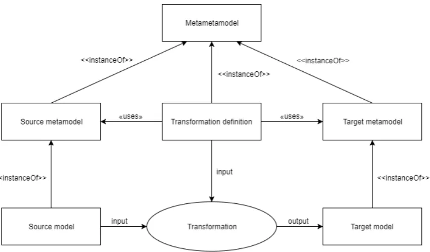
Figure 4 shows how transformations work in MDE, and how this relates to models and metamodels. A source model is translated to a target model, which can be, for example, a PIM that is transformed to a PSM. The transformation uses as input the source model and the transformation definition. The transformation definition is based on the metamodel of the source and the target model. This transformation therefore knows which elements are in both models. The transformation definition describes how an element in the source model should be transformed to an element of the target model. This transformation definition, the source metamodel, and the target metamodel are all instances of a metametamodel.
Figure 4 Transformation in MDE
[image:16.595.78.503.450.699.2]17
2.1.2 Use cases
Since OMG launched MDA in 2001, many usages of MDA and MDE have been presented both in research and in practice. Three main application scenarios can be identified: (1) automating software development, (2) system interoperability, and (3) reverse engineering [12].
In the first scenario, software code can be generated automatically from the models.
Because metamodels are available, the (software) developer exactly knows what information can be in the models. Model-to-model transformations and model-to-text transformations can be created based on these possible model elements. To create a new piece of code, one creates a new instance of the metamodel (a model) that contains the specific information, and code can automatically be generated for this model. This technique is especially useful in case code needs to be generated often. For one-off tasks the overhead of modelling and writing the transformations is too much, but for repetitive tasks this can be very beneficial. Another advantage is that everybody can create such a model, and software developers are in theory not necessary anymore to create the whole software, only for writing and updating the transformations.
In the second scenario, there are different systems with a similar purpose which each have their own metamodel. In this scenario, also a pivot metamodel is created which is a
metamodel that covers all the different systems. Then, transformations can be written and executed from the metamodel of the different systems to the pivot metamodel and vice versa. In this way, a model of each system can be translated to a model of another system via the pivot metamodel. The alternative is to write a transformation between all metamodels of the different systems directly. However, using n systems, one needs to write n*(n-1) transformations. When a new system is introduced, again n transformations need to be written. This quickly explodes. By using a pivot metamodel, only two transformations need to be added for a new system (from and to the pivot metamodel) and the new system can directly be transformed to any of the other systems.
In the third scenario, MDE is used to extract the models of already existing systems, often legacy systems. One starts with some low-level models and based on these models one can extract higher level models. From the discovered higher-level models, a new system can be generated using the first scenario. In this way, a legacy system can be modernized.
2.1.3 MDE in practice
There are many different reasons to apply MDE in a project or organization. In different studies about MDE in practice, the most named benefits are: a clear (well-documented) software architecture, conceptual simplicity, efficient implementation, high scalability, flexibility, higher productivity, and improved communication within development teams and with external stakeholders [14]–[16]. Especially for labor-intensive and error-prone
development tasks, MDE is deemed useful [16], [17].
18
2.2 Process Mining (PM)
PM is a research discipline that aims to discover, monitor and improve actual processes by
extracting knowledge from event logs readily available in today’s information systems. The IEEE Task Force on PM has written a manifesto, which presents guiding principles and challenges for PM [19]. A lot of the research about PM and the principles outlined in this research are based on this manifesto. An overview of PM based on the manifesto is also has been published in [20].
2.2.1 Techniques
PM is a technique that is currently rapidly developing. More applications and extensions are discovered on a regular basis. Three main techniques form the foundation of PM: process discovery, conformance checking and enhancement [21], [22].
Process discovery uses an event log as input and automatically constructs a process model from this event log without any a priori information. The resulting process model can be presented in different formats and depends on the algorithm used to discover the process model. The most basic process discovery algorithm is the alpha algorithm, which produces a Petri Net. This is a simple algorithm, which has several limitations like its inability to discover concurrent processes. There are also other (more advanced) algorithms like the region-based approaches, which can discover more complex model structures, and the heuristics miner, which focuses on noise and incompleteness.
Conformance checking uses as input both a process model and an event log. Both are then compared to see if the reality matches the expected or desired behavior. The input model can be a handmade model. Typically, four quality dimensions for comparing models and logs are considered:
- Fitness. The more logs can be replayed on the model, the higher the fitness. - Simplicity. The simplicity of the model. A principle called Occam’s Razor is often
important here. The simplest model that can explain the behavior seen in the log is considered as the best model.
- Precision. Whether the model does not allow for too much behavior. If the model is not precise, the model is underfitting; the model over-generalizes the example behavior of the log.
- Generalization. If the model does not restrict the behavior too much to the examples of the log. If the model is not general, the model is overfitting; the model is too specific for the example data in the event log.
Conformance checking results can be viewed from two angles: the model does not capture the real behavior (the model is wrong) or reality deviates from the desired model (the actual behavior is not as it should be). In the former viewpoint the model is a descriptive model, in the latter a normative model.
Enhancement can extend or improve the existing process model using the event log. This can be done in several ways. Non-fitting process models can be corrected using diagnostics provided by alignment. Event logs can also contain additional information about, for
example, resources, timestamps, and case data. This extra information can be used, for example, in the discovery of roles, construction of social networks, analyzing resource performance, and creating decision trees.
2.2.2 PM in software engineering
19 The research on PM in software engineering can roughly be separated in two categories: PM used for the software development process and PM used in the software process, i.e., the process within the product. Since the research in this project focuses on evaluating the software and its content, the latter category is of interest for us.
Van der Aalst et al. [24] present a technique to compare the actual behavior in an
information system with the intended or expected behavior. In this approach, delta testing is used to compare the discovered process model with the predefined model, and conformance testing is used to quantify the fit between the actual and predefined model. Poncin et al. [25] present FRASR (Framework for Analyzing Software Repositories), a framework that enables the use of PM techniques on combined data of multiple repositories, like code repositories, the bug tracking system, mail, etc. Using the combined view, more valuable information can be extracted. Van der Aalst et al. [26] present a technique to analyze software in vivo, in other words in their natural habitat. By observing running systems, and collecting and analyzing data of these systems, descriptive models can be generated, and these can be used to respond to failures. Rubin et al. [27] present the results of applying PM techniques on several systems used in the touristic domain. In this case, user interaction is recorded in event logs. Based on these logs, process and user interface flow models are automatically derived.
We also investigated which PM techniques are most useful for evaluating software products. Ailenei et al. [28] developed a set of use cases and validated these use cases by means of expert interviews and a survey. In this thesis, the role of PM can be compared with the role of the process analyst from [28]. The paper shows that especially the use cases related to process discovery and the time perspective are relevant for this kind of research.
Organizational aspects and compliance are deemed less useful.
Most of the PM research ends with the results of the techniques and does not mention what happens further with these results. Work has been presented to visualize the results in charts or through simulation [29], [30]. However, one still needs to interpret the results himself.
2.3 Combining PM and MDE
In the literature research so far, PM and MDE are described extensively. However, the combination of both techniques has not been extensively discussed. We found no
references that uses MDE to analyze or predefine the PM results. Even though this exact topic has not been studied yet, there is some research that is worth mentioning.
Some research is about using the MDE models for conformance checking. Simonin et al. [31] presents a research where models are automatically designed by using MDE. These models are then used by certain people, e.g., the supervisor, to detect anomalies in the processes discovered by using PM techniques. Bernardi et al. [32] also uses the models created by using MDE as a normative model for the results of PM, in this case to improve the security of web information systems. The normative model is generated based on the specification of the system.
Mazak et al. present a combination of PM and MDE to tackle the MDE limitation that it is now mainly used for prescriptive models. However, to make them beneficial, the models should be updated at runtime. Execution-based model profiling is proposed to tackle this problem [33], [34]. In this case, the runtime character of PM is combined with the
20
3 Case study: Mobina
This chapter introduces the case study of this thesis, the content-intensive application Mobina. First, Mobina is introduced. Then, we motivate why Mobina is a relevant case study as well as how Mobina can benefit from the UWAT. Finally, the different components of Mobina are introduced.
3.1 Mobina application
To validate the architecture designed in this research, a case study is used to create an implementation of the UWAT and to validate the design. The SUA used in this case study is Mobina. Mobina is a content-intensive application which helps SME manufacturing
companies identify what changes with a high impact on the way they work mean for their organization, processes and information landscape. Mobina positions itself as a Knowledge-as-a-Service (KaaS): their web application gives access to scarce but crucial knowledge to start implementing a high-impact change.
The content in the application is provided by the team behind Mobina consisting of
experienced consultants, leadings scientists and young talent. They have a lot of knowledge on the edge of business and IT, which is scarce and therefore often expensive. By
standardizing and automating this knowledge, Mobina wants to make this knowledge accessible to all manufacturing companies, including SMEs which do not often have the resources or culture to hire the alternative, namely a consultant.
To make the knowledge understandable and approachable for the manufacturing companies without human intervention, Mobina developed their own modelling technique, which led to an industry reference model. Around this knowledge in Mobina, there is an extensive collaboration environment such that employees throughout the entire manufacturing company can discuss what a (possible) change means for their processes and information landscape. By involving the people within the organization, Mobina also contributes to mobilizing the organization for the change to come.
3.2 Relevance
Mobina contains a lot of complex content and concepts. Besides that, Mobina aims at making this knowledge accessible to a whole range of people in the company, all with different background and education. To ensure everybody can grasp the content and
actively participate in the process, the team behind Mobina has discussed internally, but also with potential customers, partners, and key opinion leaders, about how to structure and present the content and the software. This has led to a unique way of modelling the content, which are called reference models in Mobina, and a user interface that supports this way of modelling.
21
3.3 Mobina components
The content and the software of Mobina is constantly under development. This has led to a difference in functionality between when the research was started, and these data were collected, and the functionality the software has currently. This section discusses the software as when the data were collected.
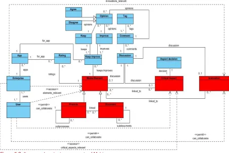
Figure 5 shows the major software and knowledge components of the Mobina software. This model does not represent the actual definition in code but only helps describing the
[image:21.595.73.526.224.526.2]components of the Mobina software. The blue components are data that are entered by the customers of Mobina, whereas the red components represent content delivered by Mobina.
Figure 5 Software and content components of Mobina
Mobina contains three different kinds of content objects: the reference model, the critical aspects and the innovations. The reference model is the part of the software that is most used by the customers. It consists of model elements, which can be processes or
22
Figure 6 A process in the Mobina reference model
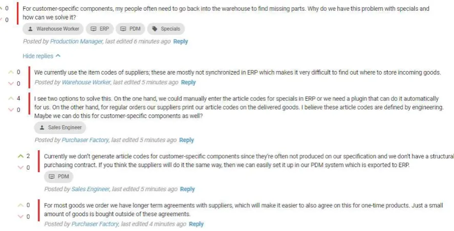
A collaboration environment is offered for all model elements. This consists of three major parts: discussion, keep/improve and ratings. All three parts are always linked to one model element, i.e., to one topic. In the discussion the users can place free-format comments and have an interactive discussion with each other. Figure 7 shows an example discussion. Each comment can have one or more tags. All enterprises can add for their company which
applications they use, in free-format. These applications can then be tagged in comments, but are also the foundation of the keeps, improves and ratings. Using ratings, a user can give a rating between 1 and 7 and an explanation for an application. The users can also collaborate on a list of things they want to keep or improve in their applications. Since the discussion and the keeps and improves are collaborative elements, other users can give their opinion easily by saying whether they agree or disagree (similarly to thumbs up/down).
[image:22.595.80.524.468.694.2]23 The second type of content objects is critical aspects. These are complex business aspects that have a deep impact on the IT landscape of a company. It is often hard for a company to oversee the impact of these aspects on IT applications, which is why Mobina defined them from a business perspective. For each of these aspects there is again a discussion
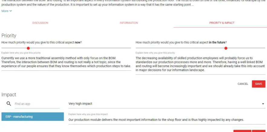
[image:23.595.72.514.229.447.2]functionality, which is similar to the discussion of the model elements. The critical aspects are also linked to the relevant model elements to enable the discussion in a broader perspective. For each of these aspects, the users can also determine the priority of the critical aspect now and in the future, and the impact on their IT landscape. In this way, their impact is discussed, and the company establishes an agenda for a futureproof IT landscape. Figure 8 shows an example of the priority and impact given for a critical aspect.
Figure 8 Priority and impact for a critical aspect in Mobina
The last type of content object is innovation. Innovations in Mobina are the well-known innovations in the manufacturing industry like Internet of Things, Smart Manufacturing etc. The role of innovations in Mobina is to include them in the entire discussion and assess the impact of the innovations on the processes and information landscape of the company. The innovations are therefore linked to model elements. For each innovation, there is again a discussion space, which is the same as for the model elements and the critical aspects.
Before the company starts using the software, Mobina asks the contact person some questions to configure the software. Based on these questions the typology of the company can be made and the relevant parts of the reference model, as well as the relevant critical aspects and innovations can be determined. The company also has possibilities to restrict the user’s permissions. Figure 5 shows that user access to model elements, aspects and innovations can be restricted. The configuration of the content and the permission system can be relevant for the user workflow analysis, since not all functionality and content will be available for all users.
24
4 Solution
This chapter presents our solution. The chapter starts with the functional, non-functional and domain requirements for the UWAT architecture. Then the high-level architecture and its external interfaces are discussed. Finally, we discuss the different techniques selected to implement the UWAT and their combination.
4.1 Requirements
The requirements for the UWAT architecture, referred to as system in the requirements, are divided into three categories (according to the division of Sommerville [35]): the functional requirements, non-functional requirements, and domain requirements.
These requirements reflect what is needed to perform user workflow analysis on content-intensive applications and make an architecture that enables all different SUA owners to achieve their objectives. They do not represent what the SUA owner would want to achieve with this architecture.
4.1.1 Functional requirements
Functional requirements are defined by Sommerville as follows: “statements of services the
system should provide, how the system should react to particular inputs and how the system
should behave in particular situations”. For this research, the following functional requirements are defined:
1. The system should be able to extract the specified patterns from the input data of the system.
2. The system should be able to give users insights in the data that cannot be directly obtained from the data.
3. The system should be able to process the data in a deterministic way. 4. The system should be able to handle different versions of the input data. 5. The system should be able to provide the results specified by the users.
6. The system should be able to use the information about the content-intensive application in its analysis.
7. The system should return a data set with the outcomes of the analyses.
4.1.2 Non-functional requirements
In this report, the definition by Kotonya and Sommerville is used for non-functional
requirements: “Requirements which are not specifically concerned with the functionality of a
system. They place restrictions on the product being developed and the development process, and they specify external constraints that the product must meet” [36]. For this research, the following non-functional requirements are defined:
8. The system should need no user interaction after the specification of the analysis. 9. The system should have as much as possible generic analyses that are applicable to all
content-intensive applications. 10. The system should be flexible.
10.1. The system should be easily extendable with new analyses.
10.2. The system should be easily made applicable to new functionality of the product that is analyzed.
11. The system needs to be presented to and used by the user as one system even if it is an implementation containing multiple tools and techniques.
12. The data integrity should remain when data needs to be converted to another format within the system.
25 14. The system should be able to perform the analysis within reasonable time2.
4.1.3 Domain requirements
Domain requirements are defined by Sommerville as follows: “Requirements that come from the application domain of the system and that reflect characteristics of that domain". In this research, the requirements related to the input and output data of the architecture to be developed are part of the domain requirements.
15. The input data should have timestamps.
16. The output data of the system should be a standardized format that can be used by different visualization tools.
4.2 High-level architecture
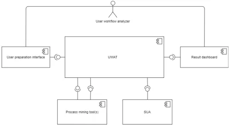
Figure 9 shows a component diagram which represents the UWAT and its interfaces to the external environment. The UWAT implements the user workflow analysis. It processes input data that it receives from the user preparation interface and has as an output the information for the result dashboard. This component is implemented using MDE. The next chapter discusses the different models and transformations.
[image:25.595.70.540.332.589.2]
Figure 9 High-level architecture
The user preparation interface is the interface in which the user workflow analyzer can decide what they want to analyze, as well as setting some possible parameters for this analysis. The options, parameters and data sets are defined by the SUA owner and are predefined and implemented before a user workflow analyzer starts analyzing the SUA. The selected data set and options are passed to the UWAT. The result dashboard is the interface to the user workflow analyzer to present the outcomes of the analysis. These outcomes are passed from the UWAT to the dashboard. For the user workflow analyzer these two
interfaces may be the same, but they represent completely different views and are therefore modelled separately here.
26 The user preparation interface and result dashboard are intentionally separated from the implementation of the UWAT. The implementation is the responsibility of the SUA owner. In this way, the SUA owner has the flexibility to determine how to visualize the options and results. It also gives the options for extra pre- and post-processing.
There are three other external interfaces to the UWAT. Two of them are with one or multiple PM tools. The implementation of PM is not part of the UWAT. There are many (open source) tools available which can deliver the requested PM results. By keeping PM separate, the user can benefit from research and developments in these tools. The implementation of PM is treated as a black box here. There are only two interfaces: one to specify the results and one to extract the outcome of the PM plugins.
The final interface is with the SUA. This interface represents the information that is extracted from the SUA and is used in the user workflow analysis. As discussed in Chapter 1, there is no direct link between them. However, there is an information exchange which is
represented by the interface in Figure 9. This information exchange includes the SUA data and the log data. We assume the log data will be passed to the PM tools via the UWAT.
4.3 Techniques
In this architecture, the techniques PM and MDE are used. PM is used to extract the user workflow from the event log data. As discussed in Section 2.2.2, for this type of analysis the strength of PM is discovering processes and analyzing time series. However, there is no standardized way yet to analyze the results of the PM plugins, i.e., the different PM algorithms and techniques; this is left up to the user.
MDE is introduced in this project to bridge the gap from the PM results to results of interest for the user workflow analyzers, because of its characteristics described in Section 2.1.3. MDE is used to configure the PM and interpret the results in a standardized way. Since MDE abstracts certain concepts, it has the potential advantage to implement (part of) this design for multiple SUAs, i.e., not specific solutions for every single SUA. Its main drawback is that it mainly works if there is a small DSL. This will probably not impose any limitations, since the design only focuses on the user workflow analysis of content-intensive applications, which is already a narrow domain. Another drawback is that the tools are often limited to one platform. Since this design presents a stand-alone tool this is also not expected to impose a limitation.
27
5 (Meta)models and transformations
This chapter presents the different metamodels and transformations used to implement the UWAT. Firstly, the transformation chain is presented to give an overview of the
implementation. Next, the five metamodels are introduced, including an illustrative example of the case study. Finally, the four transformations are discussed. For the applicable
transformations, also the format of the input and output data of the UWAT is introduced.
[image:27.595.64.568.253.538.2]5.1
Overview
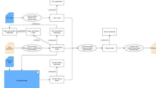
Figure 10 shows an overview of the transformation chain used in our solution. This figure only contains the design details related to MDE (i.e., the models, metamodels and transformations). The blue elements represent external information or tools. The orange elements represent the data exchanged through the interfaces with the user workflow analyzer.
Figure 10 Transformation chain
5.2 Metamodels
To implement the transformation chain, we defined the following five metamodels: SUA metamodel, plugin specification metamodel, user specification metamodel, Process Mining metamodel, and result metamodel. We defined all metamodels as generic as possible, so it could easily be applied to different SUAs. For each metamodel, a simple example from the case study is presented to illustrate the models that instantiate the metamodel.
5.2.1 SUA metamodel
28 We illustrate the SUA metamodel with the metamodel created for the case study in Figure 11. The main content class represents two attributes that are relevant for every SUA: the name of the application and the version. The name of the application specifies the SUA and can be an ID or another discriminating attribute that the SUA owner uses. The version is added to differentiate between different version of the SUA (or content versions if
[image:28.595.71.311.184.412.2]applicable). The other classes are SUA specific. For the case study, the content elements were needed to include the structure and the names in the result dashboard.
Figure 11 Mobina SUA metamodel
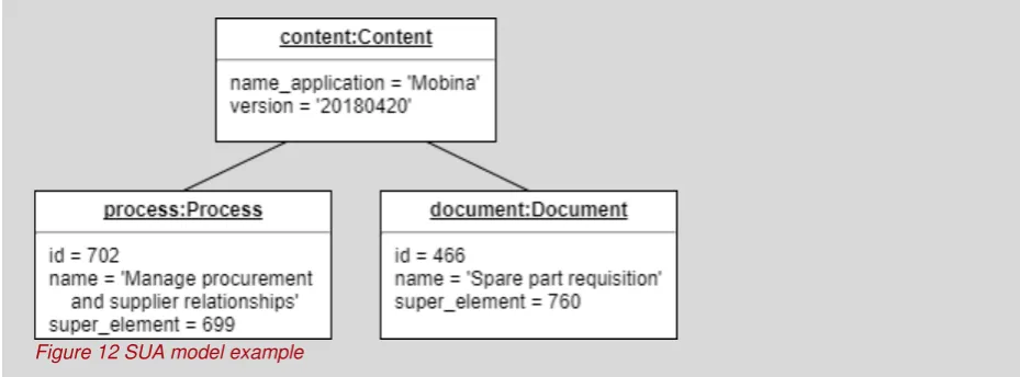
Example case study
In the case study, the SUA metamodel is used to store the names and hierarchy of the reference model in the Mobina software. The model instance of this metamodel
containing one process and one document looks like:
[image:28.595.71.536.549.721.2]29
5.2.2 Plugin specification metamodel
The PM execution is treated as a black box in the architecture. External tools are used to execute the PM algorithms. However, to establish what analyses are possible, one must know what algorithms are available and the input and output of these algorithms. Therefore, we introduced the plugin specification metamodel. An instance of this metamodel represents a plugin of a PM tool.
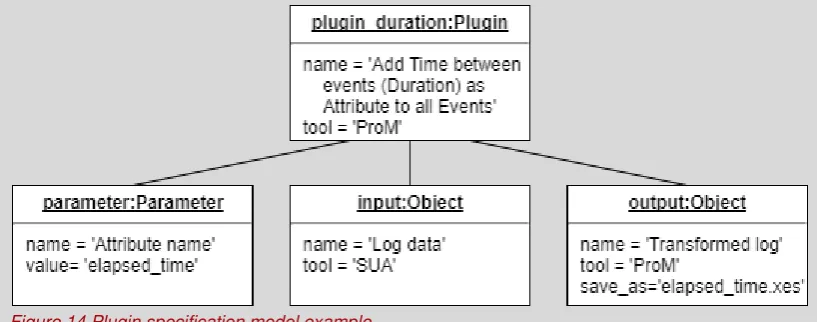
[image:29.595.73.541.257.338.2]Figure 13 shows the plugin specification metamodel. The metamodel defines a generic way to model plugins. An advantage of this generic setup is that it can be applied to different tools and plugins. This also raises the opportunity to share the specification among different SUA owners. In the plugin the tool and the name of the plugin are specified. The plugin has zero or more parameters, which are also generically defined to make them tool and plugin independent.
Figure 13 Plugin specification metamodel
Each plugin can also have zero or more input objects and zero or more output objects. This represents the information that must go into the plugin, and the different outputs. The outputs of one plugin can then be the input of another plugin. These can be from different tools, so next to the name of the objects also the tool is defined. The last attribute is save_as. In this attribute one can find the name of the file, which can be used to find the correct result file for the rest of the execution.
Example case study
In the case study, three plugins are defined in compliance with the plugin specification
metamodel. One of the plugins is the plugin ‘Add time between events (Duration) as Attribute to
all Events’ of the tool ProM. The input is the log data and the output a transformed log file. There
[image:29.595.82.491.575.736.2]is one parameter, which represents a new attribute name. For this plugin the plugin model instance looks like:
30
5.2.3 User specification metamodel
The user specifies what he/she wants to analyze through an interface. This specification is then passed to the UWAT, which processes and prepares these data, so it can be used for PM and the rest of the analysis. What the user wants to analyze is defined in the user specification metamodel.
[image:30.595.66.411.255.541.2]Figure 15 shows the user specification metamodel. All classes are generic except for the definition of the datatypes, which is an enumeration. The architecture assumes that every analysis analyzes one data set at the time. This was decided to create a clear result for the end user. However, the model can easily be adapted to support multiple data sets in one analysis, when this is deemed beneficial. When the architecture is applied to a different SUA, the SUA owner defines the types of data sets available. In the case study, we could evaluate the model elements (i.e., the processes and documents) or the different tabs (i.e., different functionalities at a model element).
Figure 15 User specification metamodel
For each dataset options are available. These options are predefined by the SUA owner when the architecture is implemented. In other words, the SUA owner must determine what could be analyzed by the user workflow analyzer. This should be based on the business objectives of the SUA. For each option, the SUA owner can also define a set of parameters (e.g., how many results should be returned). For each option, a set of plugins should be selected. The plugins are instances of the plugin specification model. To each selected plugin an order number is added. Based on the order numbers and the information from the plugin specification models, the PM instructions can be defined for the tool to execute them. The implementation of these instructions depends on the external PM tool. It is up to the implementation of the PM to ensure these plugins can work together.
31 This metamodel contains a lot of flexibility, because we want the architecture to be flexible. This way different kind of requirements and analyses that SUA owners might have are supported. However, this also means that this model and its implementation need to be discussed carefully when the architecture is implemented, to make sure the user workflow analyzer can effectively execute his task.
5.2.4 Process Mining metamodel
The PM metamodel is designed in a way that it captures the relevant results of the PM techniques and algorithms, but also generic enough to contain no implementation details of specific plugins. The PM metamodel presented in Figure 17 models two important result concepts of PM: analyzing the event log data and discovering a process model. This model can be extended with other PM concepts (d, conformance checking). The PM metamodel contains the combined results of all PM executions and is not limited to one plugin
execution.
Example case study
In the case study there is a data set with the data type ‘Model_elements’. For this data set
[image:31.595.75.541.262.512.2]three options are defined. For the first option, there are two parameters, which are identified by their parameter id. One PM plugin is specified for this option, the example of the previous metamodel. The model instance for this option is:
32
Figure 17 Process Mining metamodel
The two basic elements of PM results are nodes and transitions. Nodes are the different places visited, for example, the different processes and documents in the case study. The transitions are the movements from one node to another. Nodes and transitions both have a label to represent them in a generic way. Based on the context this can be processed later in the process-to-result transformation. All other attributes for nodes and transitions (e.g., frequency) are modelled in the same flexible way as the parameters in the user specification metamodel.
In the metamodel, two potential outcomes of PM are modelled. First, the process class in the metamodels represents a discovered process by a PM plugin. This is set of nodes and transitions, which are linked to the process instance. Each option can have a discovered process; they are differentiated by the option id. One can argue that the nodes are linked to the process through the transitions with a discovered process. However, some discovered processes have isolated nodes. Therefore, the nodes are also linked directly to the
discovered processes.
The second potential outcome is the enhancement of the event log or complete set of nodes and/or transitions. In this case, the nodes and transitions are enhanced with extra attributes. Because these enhanced nodes or transitions are not part of a (discovered) process, they are directly linked to the result instance via the place visited or transition made relationship.
33
5.2.5 Result metamodel
The result metamodel is a direct representation of the results for the user workflow analyzer. In other words, the user specification and the PM outcomes are already translated here to the results the user workflow analyzer specified. The result-to-dashboard transformation only needs to print these results. A great advantage of this set-up is that only once a visualization needs to be created for each result type. When a new option has the same result type as previously defined options, the same visualization can be used.
Figure 19 shows the result metamodel. The result is for the data set as defined in the user specification. Since this is only used here for printing it in the result, the data set is now a String instead of a value from the enumeration. The result can be two types: a list or trace collection. The list is simply a set of elements. A trace collection is a set of traces. A trace is a source with zero or more targets. In other words, a list only shows the elements whereas trace collections also show relations between these elements.
Example case study
The PM executions for the case study created one process discovered by a process discovery plugin. For all other options the nodes added via the place_visited relation are used. For the option used in the example of the user specification metamodel, the
[image:33.595.67.541.176.348.2]place_visited instances are used with the attribute frequency. The PM model instance for one node and transition in the discovered process, and one place visited looks like:
34
Figure 19 Result metamodel
Both lists and traces use result elements. Each result element has a name and an order number if the ordering of the result elements is relevant. To keep the result as generic as possible, the attributes are again shown as a separate class, where each attribute has a key and a value.
35
5.3 Transformations
The following transformations need to be implemented in the transformation chain.
5.3.1 Data-to-SUA transformation
This text-to-model transformation transforms the data of the SUA to a model instance of the SUA metamodel. Since the metamodel is specifically made for the SUA, also this
transformation needs to be developed specifically for each SUA. What should be in this transformation and how this input is delivered is up to the SUA owner and there are no specific constraints on this.
5.3.2 Preparation-to-specification transformation
The input for this text-to-model-transformation is the input of the user workflow analyzer in the user preparation interface. The input needs to be a JSON dictionary object according to the following format:
Example case study
[image:35.595.74.540.152.490.2]In the case study there are two lists and one trace collection as a result when all options are selected. The result model for one trace in the trace collection and one list item for the options used in previous examples looks like:
36
{
'option_id': string, 'parameters': [ {
'parameter_id': string, 'parameter_value': string }
] }
In the JSON dictionary object, for each key the value type is defined. In the case of a list, the type of the list items is within the list. There can be zero or more items in the list; only the type is defined here.
This transformation translates the input of the user workflow analyzer to an instance of the user specification metamodel. The different data sets available and the different options and related parameters available are already defined by the SUA owner upfront; the user only has these options. In the implementation of the user preparation interface, only the selected options must be added to the JSON object, i.e., if an option is in the input dictionary, this transformation knows that analysis must be performed.
Because the user specification model contains the plugin specification models, this
transformation should also know which options relate to which plugins. This transformation can translate the selected option and data set combination to a set of PM plugins.
This transformation is standard for different SUAs in a sense that the input data format can be standardized and therefore the options and parameters can be extracted from the input automatically. However, the SUA owner must extend this transformation with the relevant plugin specification models, i.e., link the different options to the plugin specification models.
5.3.3 Process-to-result transformation
This model-to-model transformation contains all the logic of the user workflow analysis and therefore there are a lot of specifics for the SUA. The input for this transformation is a PM model, a SUA model, and a user specification model. The output is a result model. This means that this transformation must know which options and parameters give which PM results and what the PM results mean. Besides the definition of the inputs and outputs, this transformation can therefore not be generic for multiple SUAs.
This has the disadvantage that the implementer of the architecture still needs a lot of knowledge about MDE and needs to understand the models. However, except for the SUA information and the data set and option definitions, all changes per SUA are confined to this transformation. All other metamodels and transformations could therefore be made generic and easily extendable to other SUAs. Due to the metamodels definition, the implementer knows what to do here. It only needs the SUA specific knowledge to implement it.
5.3.4 Result-to-dashboard transformation
This model-to-text transformation has as a sole purpose to print the results of the analysis. Because the result types are already defined in the metamodel and because these are generic, this transformation is the same for each SUA. Of course, each SUA could use the result of this transformation in their own environment to give it their look and feel, but that does not change the data output of the analysis, i.e., this transformation.
37
{
'data_set': string,
'lists': [
{
'description': string,
'ordered_by': string,
'elements': [
{
'name': string,
'order_number': int,
'attributes': [
{
'key': string,
'value': string }
]
}
]
}
],
'trace_collections': [
{
'description': string,
'traces': [
{
'source': string,
'targets': [string]
}
]
}
38
6 Implementation prototype
To validate the architecture, a prototype was implemented for the case study. This chapter discusses the implementation of the prototype. First, the scope is set, and we present the options and parameters that are implemented. Then, the different tools and techniques are introduced. This is followed up by the actual implementation, which is split up in four parts. First, the preparation that should be done upfront is discussed. Next, the user preparation interface and the generation of the input data is showed. Then, the implementation of the UWAT and PM is presented. Finally, the presentation of the results in the result dashboard are presented for this prototype. Where useful, the implementation is illustrated with
(pseudo)code or screenshots.
6.1 Scope
Before an SUA owner starts implementing a UWAT, first a list of business objectives should be defined, to determine what the SUA owner wants to achieve with the UWAT. The
complete list for Mobina can be found in Appendix A. The list does not need to be implemented completely to validate the design. Three business objectives have been implemented in the prototype. To limit the scope, these are limited to questions about the content (not the software) and to the reference model (not the critical aspects and
innovations). These objectives are selected based on their added value for Mobina and the expected benefit from user workflow analysis. The three selected objectives are3:
1. Do they come back to the same place? (1d)
2. How long do they stay at the same process or document? (1c) 3. What subprocesses or subdocuments are used? (5c)
The next step is to translate these business objectives to options and useful parameters for the user workflow analyzers. We selected the following three options and parameters:
1. Most used processes and documents a. Minimum times used
b. Limit result to top x results
2. Most time spent at processes and documents a. Minimum time spent (time in seconds) b. Limit result to top x results
3. Subelements used
a. Only direct relations (boolean)
The first option can answer the first objective, the second option the second objective and the third option the third objective. For objective 1 and 2, the parameters are a threshold and the number of results to be returned. These parameters are added to give the user workflow analyzer some flexibility in what they interpret as useful results. In a complete
implementation this may be extended with more options; these options are only included to illustrate the purpose and role of the parameters. For the last objective, the parameter illustrates a typical parameter specific for Mobina. The reference model is a complex structure, which is often difficult to understand. Parameters like this illustrate how this analysis may give added value for an SUA. For now, only direct relations are implemented.
6.2 Tools
To implement the complete prototype, different tools and libraries are used. For the entire development, the Mobina environment is used. In the backend, Mobina uses Django, which is a Python framework. The call to the different transformations for example, happens within this backend. For the frontend, Mobina uses VueJS as a JavaScript framework and