warwick.ac.uk/lib-publications
A Thesis Submitted for the Degree of PhD at the University of Warwick
Permanent WRAP URL:
http://wrap.warwick.ac.uk/110301
Copyright and reuse:
This thesis is made available online and is protected by original copyright.
Please scroll down to view the document itself.
Please refer to the repository record for this item for information to help you to cite it.
Our policy information is available from the repository home page.
T H E B R IT IS H L IB R A R Y
BRITISH THESIS SERVICE
TITLE
Collaborative Coding Multiple Access Communications
A U T H O R
Falah H assan Ali,
D EG REE...
A W A R D IN G BODY
D A T E ...
^ v e r s W O ^ a r - c V
iqqa
THESIS
NUMBER
T H I S T H E S IS H A S B E E N M IC R O F IL M E D E X A C T L Y A S R E C E IV E D
The quality of this reproduction is dependent upon the quality of the original thesis
submitted for microfilming. Every effort has been made to ensure the highest quality
o freproduction.
Some pages may have indistinct print, especially if the original papers were poorly
produced or if the awarding body sent an inferior copy.
If pages are missing, please contact the awarding body which granted the degree.
Previously copyrighted materials (journal articles, published texts, etc.) are not
filmed.
This copy o f the thesis has been supplied on condition that anyone who
consults It Is understood to recognise that Its copyright rests with Its author
and that no Information derived from It m ay be published without the
author's prior w ritten consent.
Reproduction of this thesis, other than as permitted under the United Kingdom
Copyright Designs and Patents Act 1988, or under specific agreement with the
copyright holder, is prohibited.
L J . ' I
1 2
1” T 3
1 ” 1 < ! ' 1 S 1 ' 1REDUCTION
X C L OCollaborative Coding Multiple Access Communications
By
Falah Hassan A li, B.Sc., M.Sc., AM IEE
A T hesis Submitted fo r the D egree o f
D octo r o f Philosophy
U n iversity o f W a rw ick
Department o f Engineering
June 1992
Table o f Contents
T itle P age
T a b le o f C on ten ts
L ist o f F igu res and Tables
A ck n o w ledgm en ts
Declarations
Abstract
Chapter 1: Introduction
Chapter 2: In trod u ctio n to M u ltip le A ccess Communications
2.1 Introduction
2.2 M u ltip le A c c e ss Channel
2.3 M u ltip le A c c e ss Techniques
2.3.1 F requ en cy D ivisio n M u ltip le Access (F D M A )
2 .3.2 T im e D ivision M u ltip le Access (T D M A )
2.3.3 C o d e D ivision M u ltip le A ccess (C D M A )
2 .3.4 C o lla b o ra tiv e C o d in g M u ltip le A ccess (C C M A )
2.4 M u ltip le A c c e ss Channel M odels
2.5 M u ltip le A c c e ss Inform ation Th eory
2.6 M u ltip le A c c e ss C oding/D ecoding Techniques
i l l
i
iii
v iii
x v i
x v ii
2.6.1 C o d e Constructions fo r N oiseless Channel 29
2.6.2 C o d e Constructions fo r N o is y Channel 33
Chapter 3: In form a tion Transmission C apacity o f Sin gle A ccess C han nel 37
3.1 Introduction 37
3.2 T h eo retica l Basis and D evelopm en t o f Channel C apacity 38
3.2.1 Unconstrained Channel 39
3.2.2 Constrained Channel 41
3.3 IS A / O S C Constrained Capacity 47
3.4 IS A P / O S C Constrained Capacity 52
3.5 Sim ulation Results and Discussions 53
Chapter 4: In form a tion Transmission C apacity o f M ultiple A c c e ss Channels 68
4.1 Introduction
68
4.2 T -u ser M u ltip le A ccess Com munication System
68
4.3 M o d e llin g o f T-u ser M -ary A d d e r Channel 71
4.4 M o d e llin g o f T-u ser M -ary Frequency Channel 77
4.5 M u ltip le A c c e ss Capacity 84
4.5.1 N o is e les s Channel 8 7
4.5.2 N o is y Channel
88
4.6 Sim ulation Results and Discussions 91
4.6.1 C ap acity o f T-user M -a ry A d d er Channel 93
4.6.2 C a p a city o f T-u ser M -a ry Frequency Channel 99
2.6.1 Code Constructions for Noiseless Channel 29
2.6.2 C o d e Constructions fo r N o isy Channel 33
Chapter 3: In form a tion Transm ission Capacity o f S in gle A ccess Channel 37
3.1 Introduction
37
3.2 T h eoretical B a s is and D evelopm ent o f Channel Capacity 38
3.2.1 U n constrained Channel
39
3.2.2 C onstrain ed Channel
4 1
3.3 IS A /O S C C onstrain ed Capacity 47
3.4 IS A P / O S C C onstrained Capacity 52
3.5 Sim ulation R esu lts and Discussions
53
Chapter 4: In form a tion Transm ission Capacity o f M u ltip le A ccess Channels
68
4.1 Introduction
68
4.2 T -u ser M u ltip le A ccess Com munication System
68
4.3 M o d e llin g o f T -u s e r M -ary A d d er Channel 71
4.4 M o d e llin g o f T -u s e r M -ary Frequency Channel 77
4.5 M u ltip le A c c e s s Capacity 84
4.5.1 N o is e le s s Channel 87
4.5.2 N o is y Channel
88
4.6 Sim ulation R esu lts and Discussions 91
4.6.1 C a p a c ity o f T-user M -a ry A d d er Channel 93
4.6.2 C a p a c ity o f T-user M -a ry Frequency Channel 99
Chapter 5: C o lla b o ra tive Coding/D ecoding M u ltip le A ccess Techniques 103
5.1 Introduction 103
5.2 T -user E n co d in g T ech niqu es 103
5.3 T -user D e c o d in g T ech niqu es 107
5.3.1 H ard D e c isio n (H D ) D ecod in g 108
5.3.2 M a x im u m Lik elih o o d S o ft D ecisio n (M L S D ) D ecodin g 109
5.4 L o w C o m p le x ity M L S D _ C C M A D ecod in g 111
5.4.1 D e c o d in g Procedure D escription 112
5.4.2 D e c o d in g A lgorith m 113
5.4.3 2-user M L S D _ C C M A D ecod in g Schem e 114
5.5 E rror P ro b a b ility A n alysis 117
5.5.1 S y m b o l E rror Probability 117
5.5.2 S y m b o l E rror Probability M inim isation 120
5.5.3 C o d e w o r d Error Probability 121
5.5.4 2-user C C M A D ecod in g Schem es Error Probability 124
5.6 Sim ulation R esu lts and Discussions 126
Chapter
6
: Practical C C M A System D esign 1386.1 Introduction 138
6.2 M od em T ech n iq u es Considerations 138
6.3 M F S K .C C M A M o d e m M o d e l 140
6.4 S q uare-Law D em odu lation T ech niqu e 143
6.5 Zerocrossing D em odu lation T ech niqu e 146
6.6
Quadrature D em o du latio n Tech niqu e 1516.7 2-user M F S K _ C C M A System D evelo p m en t 157
6.8
Sim ulation R esu lts and M odem s T estin g 1596.8.1 M od em s O p era tion V erifica tio n 159
6.8.2 A W G N C h a n n el Tests 159
6.9 Discussions 162
Chapter 7: C onclusions and Further W o rk 166
7.1 Conclusions 166
7.1.1 Inform ation C apacity o f Constrained S A C 166
7.1.2 Inform a tion C apacity o f M A C s 167
7.1.3 C o lla b o ra tiv e Coding/Decoding M ultiple Access Techniques 168
7.1.4 Practical C C M A M odem D esign 168
7.2 Further W o rk 169
7.2.1 O ptim isa tion o f Channel C apacity 169
7.2.2 Im proved C o lla b o ra tive Coding/Decoding Designs 171
7.2.3 A d a p tive C C M A Transmission System 172
7.2.4 M u lti-Fu nctional Signal D esign Format 173
R eferences 176
S ym bols and Abbreviation s 196
A p p en d ix A : C onditional P ro b a b ility Density Function for Quantised
A W G N C h an n el Output 201
Appendix B: Symbol Error Rate for 2-user Binary C CM A Scheme 202
Appendix C : C o d ew o rd E rror R ate Em ployin g H D D ecod in g
fo r 2-user B in a ry C C M A Schem e 205
A ppendix D : C o d ew o rd E rror R ate Em ployin g M L S D Decoding
fo r 2-user B in a ry C C M A Schem e 211
List o f Figures and Tables
F igu re 2.1 M u ltip le A ccess C om m un ication Channel 9
F igu re 2.2 C lassificatio n o f M u ltip le Access C om m un ication 9
F igu re 2.3 C lassificatio n o f M u ltip le A ccess M ethods 12
F igu re 2.4 Frequ en cy D iv is io n M u ltip le Access 13
F igu re 2.5 T im e D ivisio n M u ltip le A ccess 14
F igu re 2.6 C o d e D ivisio n M u ltip le A ccess 15
F igu re 2.7 C lassificatio n o f D iscrete Input M A C s 19
F igu re 2.8 2-user N oiseless B in ary A d d e r M A C M o d e l 20
F igu re 2.9 2-user N oiseless B in a ry O R M A C M o d e l 21
F igu re 2.10 2-user N oiseless B in a ry E xclu sive-O R M A C M od el 22
F igu re 2.11 2-user N oiseless B in a ry A N D M A C M o d e l 23
F igu re 2.12 2-user N oiseless B in a ry Sw itching M A C M o d e l 2 4
F igu re 2.13 C a p a city R egio n o f 2-user M A C 26
F igu re 2.14 T -u s e r N oiseless B in ary A d d er M A C M o d e l 2 9
F igu re 2.15 T -u s e r N o is y B inary A d d e r M A C M o d e l 33
F igu re 3.1 C han nel Capacity versus S N R fo r B inary Input A W G N
C han nel (w ith T w o E quiprobable M ass Poin ts) 4 6
F igu re 3.2 Constrained C apacities as a Function o f Input Signal
A m p litu d e 5 4
Figure 3.3 Constrained Capacities as a Function o f Normalised SNR (dB) 55
57 F igu re 3.4a Optim um M ass P oin ts Distribution o f IS A /O S C C om trainti
W ith A = 1 .0 and S C =6.0
F igu re 3.4b Optim um M ass P oin ts Distribution o f ISA /O S C Constraints
W ith A = 1 .5 and S C =6 .0 57
F igu re 3.4c Optim um M ass P oin ts Distribution o f IS A /O S C Constraints
W ith A = 2 .0 and S C =6 .0 57
F igu re 3.4d Optim um M ass P oin ts Distribution o f ISA /O S C Constraints
W ith A = 2 .5 and S C = 7 .0 57
F igu re 3.4e Optim um M ass P oin ts Distribution o f ISA /O S C Constraints
W ith A = 3 .0 and S C = 7 .0 58
F igu re 3 .4 f Optim um M ass P o in ts Distribution o f IS A /O S C Constraints
W ith A =4 .0 and S C =8 .0 58
F ig iire 3.4g Optim um M ass P oin ts Distribution o f ISA /O S C Constraints
W ith A = 5 .0 and S C =9 .0 58
F igu re 3.4h Optim um M ass P oin ts Distribution o f ISA /O S C Constraints
W ith A = 6 .0 and S C =1 0 .0 58
F igu re 3.5a Optim um M ass P oin ts Distribution o f IS A P / O S C Constraints
W ith A = 1 .0 and S C =6 .0 59
F igu re 3.5b Optim um M ass P oin ts Distribution o f IS A P/O S C Constraints
W ith A = 1 .5 and S C =6 .0 59
F igu re 3.5c Optim um M ass P oin ts Distribution o f IS A P/O S C Constraints
W ith A = 2 .0 and S C =6 .0 59
F igu re 3.5d Optim um M ass P oin ts Distribution o f IS A P/O S C Constraints
W ith A = 2 .5 and S C = 7 .0 59
W it h A = 3 .0 and S C = 7 .0 60
Figure 3 .5 f O p tim u m Mass Poin ts D istribu tion o f IS A P/O S C Constraints
W it h A =4.0 and S C = 8 .0 60
Figure 3.5g O p tim u m Mass Poin ts D istribu tion o f IS A P/O S C Constraints
W it h A = 5 .0 and S C = 9 .0 60
Figure 3.5h O ptim u m Mass P oin ts D istribu tion o f IS A P / O S C Constraints
W it h A = 6 .0 and S C = 1 0 .0 60
Figure 3.6 O ptim u m O S C A s a F u n ctio n o f Norm alised S N R (d B ) 62
Figure 3.7a Output P D F o f IS A / O S C Constraints
W it h A = 1 .0 , S C = 5 .0, M = 2 , and S N R = 0 d B 63
Figure 3.7b Output P D F o f IS A / O S C Constraints
W it h A = 1 .5 , S C = 6 .0. M = 2 , and S N R = 3 .5 2 2 d B 63
Figure 3.7c Output P D F o f IS A / O S C Constraints
W it h A = 2 .0 , S C = 6 .0, M = 3 , and S N R = 5 .3 7 7 d B 63
Figure 3.7d O utput P D F o f IS A / O S C Constraints
W it h A = 2 .5 , S C = 7 .0, M = 3 , and S N R = 6 .7 8 3 d B 63
Figure 3.7e O utput P D F o f IS A / O S C Constraints
W it h A = 3 .0 , S C = 7 .0, M = 4 , and S N R = 8 .0 6 2 d B 64
Figtire 3 .7 f Output P D F o f IS A / O S C Constraints
W it h A =4.0, S C =8 .0, M = 4 , and S N R = 9 .9 9 5 d B 64
Figure 3 .7g Output P D F o f IS A / O S C Constraints
W it h A = 5 .0 , S C = 9 .0, M = 5 , and SN R = 1 1.5 4 3 dB 64 Figure 3.5e Optimum Mass Points Distribution o f ISAP/OSC Constraints
W ith A = 6 .0 , S C =10.0, M =
6
, and S N R = 1 2.8 4 d B 64Figu re 3.8a Output P D F o f IS A P / O S C Constraints
W ith A = 1 .0 , SC =5.0, M = 3 , and S N R = -3 .0 1 d B 65
Figu re 3.8b Output P D F o f IS A P / O S C Constraints
W ith A = 1 .5 , SC =6.0, M = 3 , and S N R = 0 .5 1 2 d B 65
Figure 3.8c Output P D F o f IS A P / O S C Constraints
W ith A = 2 .0 , SC =6.0, M = 3 , and S N R = 3 .0 1 d B 65
Figu re 3.8d Output P D F o f IS A P / O S C Constraints
W ith A = 2 .5 , S C =7 .0, M = 4 , and S N R = 4 .9 4 9 d B 65
Figure 3.8e Output P D F o f IS A P / O S C Constraints
W ith A = 3 .0 , SC =7.0, M = 4 , and S N R = 6 .5 3 2 d B
66
Figure 3.8f Output P D F o f IS A P / O S C Constraints
W ith A = 4 .0 , SC =8.0, M = 5 , and S N R = 9 .0 3 1 d B
66
Figu re 3.8g Output P D F o f IS A P / O S C Constraints
W ith A = 5 .0 , SC =9.0, M =
6
, and S N R = 1 0.9 7 d B66
Figure 3.8h Output P D F o f IS A P / O S C Constraints
W ith A = 6 .0 , SC =10.0, M =
6
, and S N R = 1 2.6 d B66
Figu re 4.1 B lo c k D iagra m o f T -user M u ltip le A ccess Com munication
System 69
Figu re 4.2 N oiseless T -user B inary A d d e r M A C M o d e l 72
Figure 4.3 N oiseless T -user M -a ry A d d er M A C M o d e l 72
Figure 4.4 N u m ber o f O/P Signal L e v e ls versus I/P Signal L e v els
F o r T-u ser M -ary A d d e r M A C 73
Figure 3.7h Output PD F o f ISA/OSC Constraints
76 Figure 4.5 N o is y T -user M -a ry A d d er M A C M o d e l
Figure 4.6 Equivalent N o is y T-user M -a ry A d d e r M A C M o d e l 77
Figure 4.7a N oiseless T -u ser M -ary A d d e r M A C Output Probability
Distribution ( T = l , M =2, L = 2 ) 78
Figure 4.7b N oiseless T -u s e r M -ary A d d e r M A C Output Probability
Distribution (T = 2 , M = 2 , L = 3 ) 78
Figure 4.7c N oiseless T -u ser M -ary A d d e r M A C Output Probability
Distribution (T = 3 , M = 2 , L = 4 ) 78
Figure 4.7d N oiseless T -u ser M -ary A d d e r M A C Output Probability
Distribution (T = 4 , M =2, L = 5 ) 78
Figu re 4.8a N o is y T-u ser M -a ry A d d er M A C Output Probability
D ensity Function (T = 2 , M = 2 , L = 3 , S N R = 2 0 d B ) 79
Figure 4.8b N o is y T-u ser M -a ry A d d er M A C Output Probability
D ensity Function (T = 2 , M = 2 , L = 3 , S N R = 1 0 d B ) 79
Figure 4.8c N o is y T-u ser M -ary A d d er M A C Output Probability
D ensity Function (T = 2 , M = 2 , L = 3 , S N R = -1 0 d B ) 79
Figure 4.8d N o is y T-u ser M -ary A d d er M A C Output Probability
D ensity Function (T = 2 , M = 2 , L = 3 , S N R = -2 0 d B ) 79
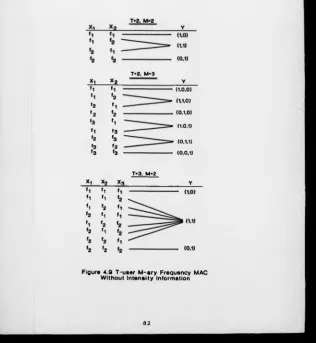
Figure 4.9 T-user M -ary Frequency M A C W ith ou t Intensity Inform ation 82
Figure 4.10 Num ber o f O/P Signal L e v e ls versus I/P Signal L e v els
For T-user M -a ry Frequency M A C W ithou t Intensity Information 83
Figure 4.11 T-user M -ary Frequency M A C W ith Intensity Inform ation 85
Figure 4.12 Num ber o f O/P Signal L e v e ls versus I/P Signal L e v els
For T-user M -a ry Frequency M A C W ith Intensity Inform ation
86
Distribution 94
Figu re 4.14 C apacity o f T -u ser M -ary A d d e r M A C W ith Actual O/P
Distribution 94
Figu re 4.15 C apacity o f T -u ser M -a ry A d d e r M A C versus E/No (d B )
(M = 2 , A n tipodal S ign a llin g S ch em e) 95
Figure 4.16 C apacity o f T -u ser M -ary A d d e r M A C versus E/No (d B )
(M = 2 , O n -O ff K e y in g S ch em e) 95
Figu re 4.17 C apacity o f T -u ser M -ary A d d e r M A C versus E/No (d B )
(M = 2 , B inary S ign a llin g S ch em e) %
Figure 4.18 C apacity o f T -u ser M -a ry A d d e r M A C versus E/No (d B )
(M = 4 ) 96
Figure 4.19 Capacity o f T -u ser M -a ry A d d e r M A C versus E/No (d B )
(M =
6
) 97Figure 4.20 C apacity o f T-u ser M -a ry A d d e r M A C versus E/No (d B )
(M =
8
) 97Figure 4.21 C apacity o f T -u ser M -ary F requ en cy M A C W ithou t Intensity
Inform ation (w ith U n ifo rm O/P Distribution) 100
Figure 4.22 C apacity o f T-u ser M -a ry F requ en cy M A C W ithout Intensity
Inform ation (w ith A ctu a l O/P D istribution) 100
Figure 4.23 C apacity o f T -u ser M -a ry F requ en cy M A C W ith Intensity
Inform ation (w ith U n ifo rm O/P Distribution) 101
Figure 4.24 Capacity o f T -user M -a ry F requ en cy M A C W ith Intensity
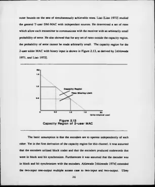
Inform ation (w ith A ctu a l O/P Distribution) 101 Figure 4.13 Capacity o f T-user M-ary Adder M A C With Uniform O/P
(w ith midpoint D ecision T h resh old s) 122
Figure 5.2 T-user C C M A Channel O/P S E R
(w ith Optimum D ecisio n Th resh olds) 122
Figure 5.3 H D . C C M A D ecoder C E R 129
Figure 5.4 M L S D _ C C M A D ecoder C E R 129
Figure 5.5 C C M A D ecod in g Sch em es C E R (C o d e 1) 130
Figure 5.6 C C M A D ecod in g Sch em es C E R (C o d e 2 ) 130
Figure 5.7 C C M A D ecoding Schem es C E R (C o d e 3 ) 131
Figure 5.8 C C M A D ecoding Sch em es C E R (C o d e 4 ) 131
Figure 5.9 C C M A D ecoding Sch em es C E R (C o d e 5 ) 132
Figure 5.10 C C M A D ecod in g Sch em es U sers Sin k S E R (C o d e 1) 133
Figure 5.11 C C M A D ecod in g Sch em es U sers Sin k S E R (C o d e 2 ) 133
Figure 5.12 C C M A D ecod in g Sch em es U sers S in k S E R (C o d e 3 ) 134
Figure 5.13 C C M A D ecoding Sch em es U sers S in k S E R (C od e 4 ) 134
Figure 5.14 C C M A D ecod in g Sch em es U sers S in k S E R (C o d e 5 ) 135
Figu re 6.1 B lock Diagram o f M F S K _ C C M A Transmission System 141
Figu re 6.2 B lock Diagram o f S q u are-La w D em odulator 144
Figu re 6.3 B lock Diagram o f Z erocrossin g C ou n tin g D em odulator 148
Figure 6.4 B lock Diagram o f Quadrature D em odulator 152
Figure 6.5 System 1 Demodulator Input and Output W a veform s 160
Figure
6.6
System 3 Demodulator Input and Output W a veform s 161Figure 6.7 Demodulator S E R versus E/No (d B ) 163
Figure
6.8
System 3 Demodulator S E R versus E/No (d B ) 163 Figure 5.1 T-user C C M A Channel O/P SERT a b le 4.2 C om posite S ign a l Sym bols F or A n tip o d a l Sign a llin g (T = M = 2 ) 92
T a b le 4.3 Com posite S ign a l Sym bols F o r O n - O ff K e y in g (T = M = 2 ) 93
T a b le 5.1 2-user U n iqu ely D ecodable C o d e 105
T a b le 5.2 Forbidden and Nearest A d m issib le C o d e w o rd s F or 2-user C ode 1 114
T a b le 5.3 D ecod in g D ecisio n T able fo r 2-user C o d e 1 116
T a b le 6.1 2-user S q uare-Law Demodulator O utput 146
T a b le 6.2 Norm alised Z C Counts w ith D iffe r e n c e Procedure 149
T a b le 6.3 Norm alised Z C Counts w ith Sum P ro ced u re 149
T a b le 6.4 2-user 2 F S K Z C Demodulator Output 151
T a b le 6.5 2-user 2 F S K W ith Intensity In form a tion Quadrature
Demodulator Output 155
T a b le
6.6
2-user 4 F S K W ith Intensity In form a tion QuadratureDem odulator Output 156
T a b le 6.7 2-user 2 F S K W ithou t Intensity In fo rm a tio n Quadrature
Demodulator Output 156
T a b le
6.8
2-user 4 F S K W ithou t Intensity In fo rm a tio n QuadratureDemodulator Output 157
Table 4.1 Composite Signal Symbols For Binary Signalling (T=M =2) 91
Acknowledgments
I w o u ld lik e to express m y sincere gratitude to m y su pervisor, Dr. B. H onary, for
his keen guidance, encouragement, and valu able com m en ts throughout this w ork. I
w ould also lik e to thank Pro fessor M . D arnell fo r his v a lu a b le comments during the
course o f this research. Thanks are due t o D r. G . M arka rian fo r his ad vice and
assistance in th e w ork o f Chapter fiv e.
A ls o I w o u ld like to thank m y colleagu es in the H u ll-W a rw ick Communication
Research G rou p , fo r their encouragements, h elp fu l com m en ts and friendship. I am also
indebted to m y cousin Issam A m in and all m y frien ds w ith ou t whose friendship,
encouragements and support I w ou ld not ha ve been able t o com p lete this work.
F in ally, I w o u ld lik e to take this opportunity to thank m y parents and every
m ember o f m y fa m ily fo r th eir support, care and continual encouragem ents through out
this work.
Declarations
T h e fo llo w in g is a list o f the materials w h ich h a ve e ith e r been published o r
submitted fo r publication , during the course o f this research program , along w ith the
sections to w h ich th ey relate. Th ese materials are the direct results o f the w o rk carried
ou t b y th e author.
- "Inform ation C a p a city o f A d d itive W h ite Gaussian N o is e Channel w ith Practical
Constraints", IE E Proceedin gs, V o l. 137, P t I, N o . 5, pp295-301, O c t 1990.
(R eleva n t to Chapter 3)
- "C a p a city o f T -u s e r C ollaborative C od in g M u ltip le A ccess S ch em e Operating o v e r A
N o is y Chan nel", IE E Electronics Letters, V o l. 25, N o . 11, pp742-744, M a y 1989.
(R elevan t to Chapter 4 )
- "C olla b o ra tive C o d in g M ultiple A ccess Channel", C o llo q u iu m o n Radio C om m unica
tio n Tech niqu es and Systems, U niversity o f W a rw ick , July 1989.
(R elevan t to Chapter 4 &
6
)- "Perfo rm an ce S tu d y o f C ollaborative C od in g M u ltip le A c c e s s O v e r N o is y Channel",
P ro ceed in gs o f Fourth Joint Sw edish-S oviet International W o rk s h o p on Information
T h e o ry , p p l57 -1 6 4 , A u g.2 7-S ept.l 1989.
(R elevan t to Chapter 4 &
6
)- "Inform ation Transm ission Capacity and Error C ontrol C a p a b ility o f Collaborative
C oding M u ltip le A ccess S ystem ", Proceedings o f Secon d B a n g o r Symposium on
Com munications, p p 195-198, 23-24 M a y 1990.
(R eleva n t to Chapter 4 & 5)
- "S o ft D ecisio n D ecod in g Technique fo r C o llab orative C o d in g M ultiple Access
Channels", Proceedin gs o f T h ird IE E C onferen ce o n T eleco m m u n ication , Edinburgh,
ppl41-147, 17-20 M arch 1991.
(R e lev a n t to Chapter 5)
- " L o w C o m p le x ity S o ft D ecisio n Decoding Tech n iqu e fo r T-u ser C olla b o ra tive C oding
M u ltip le-A ccess Channels", IE E Electronics Letters, V o l. 27, N o . 13, p p l 167-1169,
June 1991.
(R e lev a n t to Chapter 5)
- "C olla b o ra tive C od in g M u ltip le Access E m p lo yin g M anch ester and C M I Codes",
Proceedings o f Fourth B a n gor Symposium on Com munications, 2 7 -2 8 M ay 1992.
(R eleva n t to Chapter 5 )
- "C o lla b o ra tive C od in g and Decoding Tech niqu es fo r M u ltip le A ccess Channels",
Submitted fo r Publication to IE E Proceedings, P t I, M a y 1992.
(R e lev a n t to Chapter 5 )
Abstract
T h is thesis investigates collabo rative cod in g multiple access (C C M A ) channel com munication schemes. T h e C C M A schemes potentially perm it e ffic ie n t simultaneous transmission b y several users sharing a com m on channel, without su bdivision in tim e, frequency o r orth ogonal codes. T h e main areas o f investigation in clu d e the information transmission capacity fo r sin g le and multiple access channels, coding/decoding techniques and practical system design fo r C C M A schemes.
T h e inform ation transmission capacity o f a sampled and quantised single access A W G N channel is developed. It is determined and optim ised w h en th e channel input and output are lim ited by certain practical constraints. Th ese investigation s have led to the d evelo pm en t and determ ination o f the inform ation transmission ca p a city o f multiple access channels. T h e capacity o f a multiple access channel is studied fo r tw o different classes o f T -u ser channel m od els fro m both theoretical and practical points o f view . It is shown, in prin ciple, that high er transmission rates or, eq u iva len tly, m ore reliable com munication than w ith tim e sharing is achievable em p lo yin g th e same signalling
alphabet
T h e C C M A schemes, in addition to p ro vidin g the m ultiple access function, can also in corporate a certain d egree o f error control capability. T w o main decoding techniques, hard decision and maxim um likelih ood so ft decision, a re presented w ith uniquely d eco d a b le C C M A schemes. A n ew lo w com p lex ity m axim u m likelihood decoding techn ique is described and analysed. R elia b ility p erform an ce o f various collaborative c o d e s is studied b y simulation e m p lo yin g these d e co d in g techniques. It is shown that u n iqu ely decodable schemes perm it the multiple a ccess function to be com bined w ith forw a rd error correction. It is also foun d that soft d e cis io n decoding can provide an e n e rgy gain o v e r hard decision decoding.
T h e fin a l area o f investigation is a practical C C M A m odem system design to combine c o lla b o ra tive codin g and modulation. A n M -a ry frequ en cy sh ift keyin g based m odulation sch em e is described fo r the T-user C C M A schemes. T h r e e particular types o f dem odulation techniques, square-law, zerocrossing counting, and quadrature receiver, are described. T h e s e techniques are developed in softw are, tested an d evaluated o ver
noiseless and n o isy channels.
Chapter . !
Introduction
T h e purpose o f m o d em com m unication th eory is to enable the d e sig n o f systems
w h ich facilitate rapid, relia ble, and e ffic ie n t transfer o f inform ation th rou gh a medium
w h ich is called a com m u nication channel. A telephone w ire transm ission line, o r radio
frequ en cy electrom agn etic propagation system are tw o v e ry co m m o n exam ples o f
com munication channels. Intuitively, a com munication channel is an y m edium w hich
supports the propagation o f energy fro m a source to a destination with s u fficien t control
to a llo w m ovem en t o f som e data.
T h e classical m o d e l o f a com munication system has a sin gle transm itter sending
inform ation to a rec e iv e r through a channel w h ich in som e w a y corrupts the transmitted
information. T h is is a sin g le access com m unication channel (S A C ). D evelo pm en ts in
satellite com m u nication systems, com puter com munication n etw orks, m obile radio
systems, and other com m unication system s in v o lvin g multi-user ha ve le d communica
tio n systems designers to investigate the simultaneous transmission o f inform ation fro m
several terminals o v e r a com m on com m unication channel. A n important m o d el o f multi
user com munication is the m ultiple access com munication channel (M A C ) .
T h e inform ation th eo ry o f S A C [Shannon 1948] has shown that, noise and other
disturbances on the channel d o not lim it the relia bility by w h ich d ig it a l data can b e
transmitted but rather o n ly lim its the rate at w h ich data o f arbitrarily h ig h reliability can
be transmitted. T h e highest rate at w h ich such relia ble data can be transmitted o v e r a
channel is know n as the capacity o f the channel. T h e inform ation theory o f M A C has
shown that, multiple users can communicate data w ith arbitrarily small p ro b a b ility o f
error o v e r a com mon channel provided that the rates o f the individual data streams lie
w ith in the capacity region fo r the channel. T h e set o f rates at w h ich simultaneous
relia ble transmission is possible is called the capacity region o f M A C . Shannons
capacity theorem g ives us a theoretical value fo r the error fre e capacity o f a channel,
g ive n that the time taken to evaluate the data is infinite. H o w ever, in m ost practical
circumstances, this is o f little use as any practical demodulation/decoding s ch em e must
g iv e a result in a finite period o f tim e. Th erefo re, the practical system d e sig n e r must
keep in m in d the theoretical channel capacity, and probably m ore im portantly, certain
practical restrictions w hich must also be satisfied.
O n e o f the basic w a ys o f increasing the throughput o f a com m unications resource
is to m ake the allocation o f the communications resource m ore efficien t. T h is approach
is the dom ain o f multiple access communications. T h e problem is to e ffic ie n t ly allocate
portions o f the fixed communications resource to a large number o f users w h o seek to
com m u nicate digital in form ation to each other. T h ere are many w ays o f distributing the
com munications resource am on g the active users. H ow ever, the purposes h e re are to
rule out conventional channel sharing techniques such as T D M A , F D M A an d C D M A .
M o re in tu itively, the rationale behind this is to investigate collaborative c o d in g multiple
access ( C C M A ) techniques b y which a sin gle transmission medium can b e shared
e ffic ie n tly and in a distributed fashion am ong m any users.
C ollaborative codin g constructions have foun d short codes w h ich a re easy to
d eco d e such that, the a ctive users which transmit independently (i.e., w ith o u t prior
reservations and without feedback during transmission) through the same chan nel can
be d eco d ed u n iquely at the receiver. In particular, there exist collaborative c o d e s w h ich
a llo w t w o o r m ore users to share the same transmission bandwidth and a b le to
com m unicate at a com bined inform ation rate w h ich is greater than unity. T h a t is, the
summary rate o f the users is greater than the ideal rate (unity) w h ich can b e a c h ieved
by m eans o f tim e sharing o r T D M A . Sin ce th e transmission channel is alw a ys
susceptible t o external noise, a co llab o rative co d in g design needs, not o n ly to be
un iquely d eco dable but also must b e able to correct transmission errors.
In practical systems, the transfer o f co llab o rative coded messages in v o lv e s the
utilisation o f various m odules, i.e. m odulator, demodulator and the com m u nication
m edium. T h e modulator, w h ich is em p lo yed at the transmitter side, translates th e coded
m essage stream into a suitable form a t fo r transmission o v e r the m ultiple access
com m u nication medium. O n the other hand, the demodulator, is situated at the r e c e iv e r
and p erform s the reverse operation to that o f the modulator. T h e dem odu lation process
in v o lve s the detection o f th e received com posite sign al and the subsequent m a p p in g o f
these signals into the form at o f the o rigin al m essage stream.
Investigations o f inform ation transmission capacity o f both S A C and M A C ,
coding/decoding, and practical system design f o r theses C C M A schemes are o f
con siderable im portance to p ro vid e the overa ll e ffic ie n t m ultiple access system . T h e
w o rk o f this thesis is a contribution towards these objectives.
T h e seco n d Chapter o f this thesis review s the principles and various techniques
o f m u ltiple access com munications. A perspective, classification and discu ssio n o f
m ultiple access com munications are g iven . F o llo w in g this, the m ost com m on techn iques
o f M A C are discussed. A description o f C C M A schemes is also presented in th e same
section. T h e M A C m odels describing the form o f a signals interaction o v e r a channel
are presented w ith som e examples. T h e m ain achievem ents o f the inform ation theory
and coding/decoding approaches to the M A C are also b rie fly rev ie w e d and discussed
in this Chapter.
In C h apter three, the inform ation transmission capacity o f a sam pled and
digitised sin g le access A W G N channel lim ited b y input and output practical constraints
is described. T h e channel input is characterised b y th e input signal am plitude and
average pow er, and th e channel output is characterised b y the output signal c lip p in g due
to quantisation ap p lied at the receiver. T h e input signal amplitude/output sign al clip pin g
(IS A / O S C ) constrained capacity, and the input signal am plitude and average
power/output sign al clippin g (IS A P / O S C ) constrained capacity are determ ined and
optim ised separately. T h e optim um input signal am plitude distributions and the optim um
output signal c lip p in g that m axim ises the capacity are also determined. T h e s e tw o
capacities are d eve lo p e d b y softw a re and simulation results and discussions are
presented at the en d o f this Chapter. T h e w o rk described in Chapter three g a v e insight
and m ore understanding to the m ore com plica ted case o f M A C capacity w h ich is the
subject o f in vestigation in Chapter four.
Chapter fo u r is concerned w ith theoretical investigations o f the inform ation
transmission ca p acity o f M A C s . T w o particular types o f T-user M -a ry M A C models,
interesting fro m their theoretical and practical applications, are introdu ced and
described. T h e T -u ser M -a ry frequ en cy M A C is presented in tw o form s, w ith and
without inten sity inform ation o f the rec e iv e d signal en ergy level. T h e inform ation
transmission ca p acity is d evelo ped , th eoretically, in bits per channel use, f o r these
m odels in noiseless and noisy channel conditions. T h is capacity is sim ulated in softw are
fo r various transmission systems e m p lo yin g coherent and noncoherent com b in in g o f
signals at the channel and fo r various number o f users, T , and input signal levels. M .
T h e practical im plications o f the M A C capacity is also discussed.
Chapter f iv e investigates the capability o f C C M A schemes to p ro vide the
m ultiple access function as w e ll as the channel error control. U n iqu ely decodable c o d in g
schemes are g iven to p ro vid e these functions. Hard decision C C M A (H D _ C C M A ) and
maxim um likelihood soft decision C C M A (M L S D _ C C M A ) d eco d in g techniques are
presented. These techniques are described together with sym bol-by-sym bol H D
(S B S _ H D ) decoding. A n e w lo w c om p lex ity maxim um likelih oo d d eco d in g technique
is presented to utilise the error control capability. T h e decoding procedure and algorithm
fo r this technique are g ive n . A particular 2-user uniquely decodable schem e is analysed
w ith this new technique. T h e error probability is derived for the T -u ser binary channel
m odel em p lo yin g H D _ C C M A and M L S D _ C C M A decoding techniques. T h e th eoretical
calculations are presented fo r a particular 2-user uniquely decodable case. F in ally this
Chapter ends w ith sim u lation o f various 2-user uniquely d eco dable schemes. T h e
relia bility perform ance o f these codes em p lo yin g H D _ C C M A and M L S D _ C C M A is
evaluated in the p resence o f A W G N conditions. T h e results are presented in the fo rm
o f sym bol and c o d ew o rd error rates as a function o f signal to noise ratios.
Practical d esign o f C C M A m odem is investigated in Chapter six. T h e design o f
C C M A modulation schem e based on the M -ary frequency sh ift k eyin g (M F S K )
modulation scheme is described. T h ree particular types o f dem odulation techniques are
investigated w ith com b in ed collaborative coding and m odulation signals. T h e s e
techniques are square-law , zerocrossing counting, and quadrature demodulators. T h e
quadrature dem odulator is presented and described fo r tw o m odels, w ith and w ith out
intensity information. T h e o verall designed C C M A systems are d evelo p ed in softw a re,
and v e rifie d in a noiseless channel. A n assessment and com parison o f the relative
relia b ility perform ance o f these schemes is carried out b y simulation o v e r A W G N
channel. T h e relative merits o f the schemes are discussed, particularly w ith respect to
their im plem entation com p lex ity.
T h e thesis ends w ith a conclusions and further future w orks on each Chapter o f
this thesis.
This page has been intentionally left blank
Chapter 2
Introduction to Multiple Access Communications
2.1 Introduction
In this chapter, w e b rie fly review the prin ciples and techniques o f multiple access
com munications. Sin ce a general introductions to the multiple access communications
channel h a ve been g iv e n in details elsew here e.g. [M eulen 1977, M eulen 1986, El
G am al and C o v e r 1980, Farrell 1981, W o l f 1981, and Gallager 1985], the reader is
referred to these w o rk s f o r m ore thorough treatment o f the introductory material. W e
shall poin t out these w o rks w h en ever is required throughout this chapter.
2.2 M u l t i p l e A c c e s s C h a n n e l
C om petition fo r the use o f existin g communications resource leads to the
question o f simultaneous channel usage b y m ore than on e user. T h is kind o f
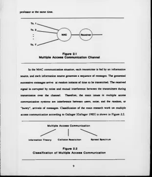
com m u nication situation is known as M A C and illustrated in F igure 2.1, in which there
are several users com m u nicating w ith on e r ec e iv e r o ver a com m on channel. Examples
o f m ultiple access communications include several mini-computers sending data
simultaneously to a large computer [A bram so n 1970, and Sch w artz 1977], several
ground stations accessin g a satellite repeater [S tig litz 1973, Ince 1978, Nirenberg and
Rubin 1978, and S o m m er 1968], several m o b ile radio to base station [Steele 1988,
Farrell 1985, and Farrell, e t al., 1986], etc. o r sim ply several students questioning a
p rofessor at th e sam e tim e.
In the M A C com m u nication situation, each transmitter is fe d b y an in form ation
source, and each in fo rm atio n source generates a sequence o f messages. T h e generated
successive m essages arrive at random instants o f tim e to be transmitted. T h e received
signal is corrupted b y noise and mutual interference betw een the transmitters during
transmission o v e r the channel. Th erefo re, the m ain issues in m ultiple access
com m unication system s are interference betw een users, noise, and the random, ex'
"bursty", arrivals o f m essages. C lassification o f the m ain research w o rk o n multiple
access com m u nication accordin g to G allager [G a lla ger 1985] is shown in F igu re 2.2.
Multiple Access Communication
Info rm a tion T h e o ry C o llisio n R e so lu tio n Sp rea d Spe ctrum
Figure 2.2
Classification of Multiple A c c e s s Communication
[image:31.329.8.319.14.376.2]T h is classification show s that there ha ve been m ain ly three bodies o f research on
m ultiple access com m u nications, each using to tally differen t models. Th ese main areas
are m u ltiple access inform ation theory, co llis io n resolution and spread spectrum.
T h e m ultiple access in fo rm atio n theoretic approach w as initiated in 1961 by
Shannon in his fundam ental paper [Shannon 1961], and established in 1971 w ith a
cod in g th eorem d eve lo p e d b y [A h lsw ed e 1971, and L ia o 1972]. T h is approach
appropriately m od els the n o ise and interference o f th e M A C but ignores the random
arrival o f m essages. It is ta citly assumed b y inform ation theoretics that the sources ha ve
a reservo ir o f data to send w h ich is n ever em pty. Thu s the theoretical results in this area
do not address the question o f the delay that arises in m ultiple access systems because
o f the random arrival tim es o f data to be transmitted. T h is assumption is adequate fro m
the th eoretical poin t o f v ie w , since the random arrivals o f messages can b e sm oothed
out b y appropriate source c o d in g [G a lla ger 1985]. F ro m a m ore practical point o f v ie w
this m o d el is not adequate because the lon g tim e intervals required fo r the source
arrivals to be sm oothed ou t are ty p ica lly fa r greater than the tolerable delays. F or m ore
inform ation refe r t o [M eu len 1977, M eu len 1986, W y n e r 1974, and E l G am al and
C o v e r 1980].
T h e c o llis io n resolution approach [M assey 1985, M assey and M ath ys 1985,
Abram son 1985, and M assey 1986], has alw a ys concentrated on the random arrival o f
m essages and on the transm ission delays w h ich are due to the interference betw een
users, but has gen era lly ign o red all other aspects o f the underlying com munication
process (e.g. n o ise). T h is approach to the m ultiple access com munication came in 1970
w ith A b ram so n ’ s A L O H A n etw ork [A bram son 1970]. T h e basic idea o f this system w as
that w h en ever a m essage (o r packet) arrived at a transmitter, it w ou ld sim p ly be
transmitted, ignoring all other transmitters in the network. I f another transmitter was
transmitting in an overlappin g interval, interference w ou ld prevent the message from
being correctly received, n o acknow ledgm en t w ould be sent, and the transmitter would
try again later. T h e later tim e w ou ld b e pseudorandomly chosen to a v o id the certainty
o f another collision i f both transmitters w aited the same tim e. O v e r the years, this basic
strategy has been im proved, generalised, and analysed in many w ays. For a more
detailed exposition o f the co llision resolution approach refer to the special issue on
random access w h ich consist o f m any papers [M assey 1985, M assey and Mathys 1985,
Abram son 1985, and M assey 1986].
Spread spectrum [C o o k , et al., 1982, Sch oltz 1982, and Pickh oltz, et al., 1982],
is a m ode o f com munication o rig in a lly developed to protect against ja m m in g in a
m ilitary environm ent. F or multiple access communication using spread spectrum several
sources can transmit at on ce using d ifferen t modulatin g sequences, and each w ill look
lik e broadband noise to the others. Th erefo re, in the multiple access spread spectrum
approach the interference fro m other users is treated as additional, poten tially intelligent,
noise. F o r m ore detailed discussions and w ork carried in this area refe r to the special
issue on spread spectrum w hich con sist o f many papers [C ook , e t al., 1982, Scholtz
1982, and Pickh oltz, et al., 1982].
2.3 Multiple Access Techniques
In m ulti user systems, there are many w ays o f sharing the communications
resource am ong the a ctive users [S k la r 1988 pp476-531]. T h e m ain objective o f all
these m ultiple access techniques is that various signals share a communications resource
without creating unmanageable interference to each other in the detection process. The
allo w able lim it o f such interference is that signals on on e com munications resource
channel should not sign ifica ntly increase the probability o f error in another channel.
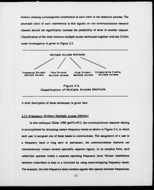
Classification o f the m ost com m on m ultiple access techniques togeth er w ith the C C M A
under investigation is g ive n in Figu re 2.3.
Multiple Access Methods
/
Freq u ency D iv isio n Tim e D iv isio n C o d e D iv isio n C olla b o rative C o d in g M ultiple A c c e s s M ultiple A c c e s s M ultiple A c c e s s M ultiple A c c e s s
Figure 2.3
Classification of Multiple A c c e s s M ethods
A b rief description o f these techniques is g ive n here.
2.3.1 F re q u e n c y D ivisio n M u ltip le A ccess ( F D M A )
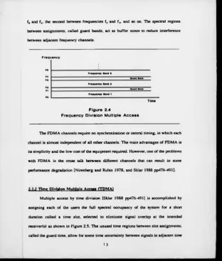
In this technique [Sklar 1988 pp476-491], th e com munications resource sharing
is accom plish ed by allocating certain frequ en cy bands as shown in Figu re 2.4, in which
each user is assigned o n e o f these bands to com municate. T h e assignment o f a user to
a frequ en cy band is lo n g term o r permanent, the com munications resource can
simultaneously contain several spectrally separate signals. In its sim plest form , each
subscriber operates w ith in a separate operating frequ en cy band. M utual interference
between subscribers is kept to a m inim um b y using nonoverlapping frequ en cy bands.
F or exam ple, the first frequ en cy band contains signals that operate betw een frequencies,
[image:34.327.11.317.2.379.2]f 0 and f „ the seco n d betw een frequ en cies f 2 and f 3, and so on. T h e spectral regions
between assignments, called guard bands, act as b u ffer zones to reduce interference
between adjacent frequ en cy channels.
F re q u e n cy
Figure 2.4
Frequency D ivision Multiple A c c e s s
T h e F D M A channels require n o synchronisation o r central tim ing, in w h ich each
channel is a lm ost independent o f a ll oth er channels. T h e main advantages o f F D M A is
its sim p licity an d the lo w cost o f the equipm ent required. H o w ever, on e o f th e problem s
w ith F D M A is the cross talk b etw een different channels that can result in some
perform ance degradation [N iren b erg and Rubin 1978, and Sklar 1988 pp476-491].
?,?.2 Time Division Multiple Agyess (T P M A )
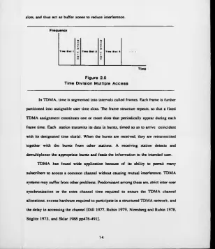
M u ltip le access b y tim e d iv is io n [Sklar 1988 pp476-491] is accom plish ed by
assigning ea ch o f the users the fu ll spectral occu pan cy o f the system f o r a short
duration c a lle d a tim e slot, selected to elim in ate signal overlap at the intended
receiver(s) as show n in Figure 2.5. T h e unused tim e region s between slot assignments,
called the guard tim e, a llo w fo r so m e tim e uncertainty between signals in adjacent time
[image:35.329.11.324.8.376.2]slots, and thus a ct as bu ffer zones to reduce interference.
Tim* »lot 1 T l«« Slot 3
Figure 2.5
Time Division Multiple A c c e s s
In T D M A , tim e is segm ented in to intervals ca lle d frames. Each frame is further
partitioned in to assignable user tim e slots. T h e fra m e structure repeats, so that a fix ed
T D M A assignm ent constitutes on e o r m ore slots that p e rio dically appear during each
fram e tim e. E ach station transmits its data in bursts, tim ed so as to arrive coincident
w ith its designated tim e slot(s). W h en the bursts are received , they are retransmitted
together w ith the bursts fro m other stations. A rec e iv in g station detects and
dem ultiplexes the appropriate bursts and feeds the in fo rm atio n to the intended user.
T D M A has found w id e application because o f its ability to perm it many
subscribers to access a com m on channel without causing mutual interference. T D M A
systems m ay s u ffer fro m other problem s. Predom inant am on g these are. strict inter-user
synchronisation o r the extra channel tim e required t o ensure the T D M A channel
allocations, e x cess hardware required to participate in a structured T D M A netw ork, and
the delay in accessin g the channel [D ill 1977, Rubin 1979, N irenberg and Rubin 1978,
S tiglitz 1973, and Sklar 1988 pp476-491].
[image:36.325.11.319.16.372.2]2.3.3 Code Division M ultiple Access (C D M A )
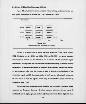
Figure 2.6, illustrates the communications resource bein g partitioned by the use
o f a hybrid com bination o f F D M A and T D M A k n o w n as C D M A .
Fre q u e n cy
Sig na l 3 : Sig nal 1 Signal 3
Sig na l 2 Signal 3 Sig na l 2
Sig na l 1 I Sig nal 2 Sig na l 1
* SM i s T im e
Figure 2.6
C o d e Division Multiple A c c e s s
C D M A is an application o f spread spectrum techniques [C o o k , et al., Scholtz
1982, Pickh oltz, et al., 1982, and Sklar 1988 pp491-493]. A spread spectrum
com m unication system can be defin ed as on e in w h ich : (a ) th e transmitted signal
bandwidth is m uch g reater than the m inim um bandwidth necessary to send the message
inform ation, (b ) all users have access to the w h o le tim e frequ en cy space o f the channel,
(c ) som e function other than the m essage is used to determ ine th e bandwidth o f the
transmitted signal, and (d ) the signals, codes, o f each user are all mutually orthogonal
in som e sense s o that the signals, codes, m ay b e unscrambled at the receiver by
correlation [In ce 1978].
Spread-spectrum techniques can be classified into tw o m a jo r categories: direct-
sequence and frequ en cy hopping. In direct-sequence schemes, the data signal is
modulated on to a d igita l, pseudo-random code sequence w h ich has a d igit rate much
[image:37.327.10.312.13.375.2]higher than that o f the data. Each o f the user groups is g ive n its o w n cod e. T h e user
codes are approxim ately orth ogonal, s o that the cross-correlation o f t w o differen t codes
is nearly zero. T h e signals to b e transmitted are m odulated b y these nearly orthogonal
sequences o v e r much broader frequ en cy band than necessary. B y using appropriate
sequences, each transmitted signal w ill look like broadband noise to the others. T h e
rec e iv e r can use the same sequence to despread the received sign al to reco ver the
transmitted messages. Frequ en cy hoppin g schemes, can be easily v ie w e d as the short
term assignment o f a frequ en cy band to various sign al sources. T h e data signal is
modulated on to a sinusoidal carrier, the frequ en cy o f w h ich is caused to change in
discrete increments, accordin g to a pattern determ ined b y a pseudo-random code
sequence. Each user is g ive n a set o f hoppin g patterns such that each pattern o f a g iven
set is nearly orthogonal to all patterns o f other sets.
T h e most important advantage o f C D M A schemes, com pared to T D M A , is that
all the participants can share the fu ll spectrum o f the resource asynchronously. There
is no need to precise tim e coordination am ong the various sim ultaneous transmitters,
i.e., the transmission tim es o f the d ifferen t users’ sym bols d o not ha ve to coincide. T h e
orth ogonality between user transmissions on d ifferen t codes is not affected by
transmission tim e variations. T h is w ill becom e clea r upon clo ser exam ination o f the
auto-correlation and cross-correlation properties o f th e codes. T h e s e schemes are
advantageous under certain circumstances in that th ey perm it fle x ib ility as to the
number and a ctivity o f the users, they degrade g ra cefu lly as the number o f users
increases, and there is an automatic trade-off betw een the number o f users and the
degree o f error protection.
T h e T D M A , F D M A , and C D M A techniques m a y also be used in either fix e d or
demand assigned m ultiple access m odes. In the fix ed assigned m ultiple access m ode the
transmission form ats o f the techniques does not change, even though the traffic load
varies fro m tim e to tim e. In the demand assigned multiple access m ode, the formats o f
transmission o f the techniques are chan ged as needed, depending on the tra ffic demand.
C onsequently, the demand assigned m ode is more efficient, but it usually costs m ore
to im plem ent and maintain [Sklar 1988 pp476-497].
2.3.4 Collaborative Coding Multiple Access (CCMA)
In situations where the bandwidth is a very restricted resource, conservation o f
the spectrum, w h ich is a valuable and fin ite resource, is v e ry important. For example,
the radio frequ en cy bands represent an in flexib le resource and it is unlikely that
sign ifica n tly larger frequ en cy bands w ill becom e available. Th erefore, it is necessary
to investigate e ffic ie n t w ays o f sharing the available spectrum channels between as
m any users as possible. It is also o f considerable im portance to use a sim ple and
e ffe c tiv e m ultiple access cod in g technique capable o f error control as w e ll as the
m ultiple access function. T h e C C M A schemes permits potentially effic ie n t simultaneous
com m unications b y tw o o r m ore users in the same bandwidth without subdivision in
tim e, frequ en cy o r orthogonal cod e, though this scheme m ay be used in a m ixed format
w ith T D M A , F D M A , C D M A . It a llo w s a substantial increase in the number o f users
that can access the system simulateneously, leading to a higher com bined information
rate and hen ce a potentially m ore e ffic ie n t system. In addition to p ro vidin g the multiple
access function these schemes can incorporate certain degree o f error protection against
noise [F arrell 1981].
In co llab o rative codin g, digital m odulation and coding are intim ately related, and
the sim ultaneous signals fro m various users are demodulated together, as a combined
m u lti-level signal. T h is perm its the use o f r ela tiv ely short and sim ple codes in contrast
to the spread spectrum case. It can also be u sed w ith the single access m odulation
techniques (e.g. am plitude sh ift keyin g, phase sh ift k eyin g and frequency sh ift keyin g),
and applies to binary as w e ll as m ulti-level sign als, though at the cost o f an increase
in com p lex ity.
T h ese techniques ex ist w hich lie b etw een the tw o extrem e cases o f
TDMA
andC D M A , and o ffe r in certain circumstances th e p o ssib ility o f rate sums high er than unity
w ith m odest synchronisation requirements [F a rrell 1981]. In
TDMA,
either strict interuser synchronisation, o r poten tially wasteful tim e slot allocation is required. W h ere in
C D M A , simultaneous transmission without inter-user synchronisation can b e achieved,
but this can be wasteful o f bandwidth because o f the rela tively lo w number o f users that
can operate simultaneously.
C ollaborative co d e s exists fo r M A C and broadcast channel (B C ) [Farrell, et al.,
1986]. In the M A C case, each user is p ro vided w ith a code w hich enables the receiver
to d eco d e the individual in form ation streams, b y detecting the resulting com bined
signal. In the B C case, a com bin ed coded sign al is transmitted, and each rec e iv e r is able
to detect and decode th e inform ation destined f o r it. T h e B C is the inverse o f the M A C ;
the sources and their com m o n encoder are a ll at the same locations, wh ereas the
decoders and associated sinks are in d ifferen t locations. T h e inform ation broadcast may
be p riva te to each sink, o r m ay have com m o n elements.
T h ese techniques ha ve many applications, fo r exam ple, digital m o b ile radio
com m u nication systems [F arrell 1983, Farrell 1985, and Farrell, et al., 1986], in w hich
they can b e applied to both m obile-to-base and base-to-m obile transmission. These
techniques ha ve also been proposed fo r optical fib re communication system s [B rid ge
1986] and ty p es o f random access M A C , such as a satellite asynchronous m ultiple
access system [ W o l f 1978, and W e ld o n 1978].
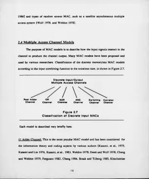
2.4 Multiple Access Channel Models
T h e purpose o f M A C m od els is to describe h o w the input signals interact in the
channel to produ ce the channel output. M any M A C m od els h a ve been proposed and
used b y variou s researchers. C lassificatio n o f the discrete m em oryless M A C m odels
according to th e input c om bin in g function in the noiseless case, is shown in F igu re 2.7.
Discrete Input/Output
Multiple Access Channels
Real A d d e r O R X O R C h a n n e l C h a n n e l C h a n n e l
A N D S w itc h in g C olliaion C h a n n e l C h a n n e l C hann el
Figure 2.7
C lassification of Discrete Input M A C s
Each m od el is described v e ry b rie fly here.
(i) A d d er Channel: T h is is the m ost popular M A C m o d el and has been considered fo r
the in fo rm atio n th eo ry and c o d in g aspects by various authors [K asam i, et al., 1975,
Kasam i and L in 1976, Kasam i, et al., 1983, W e ld o n 1978, D eatt and W o lf 1978, C hang
and W e ld o n 1979, Ferguson 1982, Chang 1984, Braak and T ilb o r g 1985, Khachatrian
[image:41.329.10.314.6.372.2]1982, Khachatrian 1984, and W ilso n 1988]. T h e channel output sym bol value is the
arithmetic sum o f the input sym bol values, in the absence o f noise. T h e T-user noiseless
adder M A C is d efin ed as a channel w ith T-input, and on e output g iv e n by;
w h ere X , is th e i-th channel input, Y is the channel output and the sign denotes real
addition. F or exam p le, consider the 2-user noiseless binary adder M A C shown in
Figu re 2.8.
0
1
-1 1 --- *--- 2
Figure 2.8
2 -u se r N o ise le ss B inary Adder M A C Model
It has tw o inputs, X , and X ^ i O . l }, and on e output Y , w h ich is the ordinary arithmetic
sum o f the inputs, Y = X , + X 2, Y e { 0 , l , 2 } . T h e arrowed lines represent the channel
conditional pro b ab ilities p ( Y | X ,,X 2). T h e adder channel is a lso know n as the binary
input erasure M A C [W o l f 1975], because the output sym b ol "1 " cannot be
unambiguously d eco d ed , ev en in the noiseless case.
(ii) O R Channel: This m od el is used b y various researchers in d iffe re n t communication
situations [S o m m er 1968, C oh en , e t a l„ 1971, V ite rb i 1978, G y o r fi and K erekes 1981,
and W o l f 1981]. T h e output o f th e channel can b e written f o r th e T -user noiseless
channel as;
X,
(2
.2
)i
-1
w h ere the "V " sign is lo g ic a l O R and X|S{0 1 }. T h a t is, i f X f d en otes the binary input
o f the i-th user, then the output o f the channel is zero i f and o n ly i f X ,= X 2=...X T=0.
F or exam ple, the 2-user noiseless binary O R M A C is shown in F igu re 2.9, where the
channel output is "0 " i f X , = X 2= 0 and "1 " other w ise.
X,
X 2
Y
Figure 2.9
2 -u se r N o is e le s s B inary O R M AC Model
(iii) E xclu sive-O R (M o d u lo -2 ) Channel: T h is channel [W o lf 1975, and Farrell 1981),
output is m odulo-2 sum (e x c lu s iv e -O R fu n ction ) o f tw o cm- m ore input values. Thus all
inputs and the output ha ve th e same alphabet ( 0 , 1 ). This chan nel is also known as
m od u lo-2 addition channel. T h e T -u ser noiseless channel output can b e written as;
(2 .3)
where the sum m ation sign " 2 " is o v e r G F (2 ) and X , e { 0 , l } . For exam ple, the 2-user
noiseless binary ex c lu s iv e -O R M A C is show n in Figure 2.10, where the channel output
is the m odulo-2 sum o f tw o binary inputs.
X ,
X 2
Y
Figure 2.10
2 -u se r N o ise le ss Bin ary Exc lu sive -O R M AC Model
(iv ) A N D C hannel: T h is channel is also called binary m ultiplyin g channel as mentioned
in [M eu len 1977]. T h e capacity reg io n and cod in g strategy fo r this channel m od el is
considered b y [S ch alk w ijk 1982, and S ch alkw ijk 1983]. T h e noiseless T -u ser channel
output can be w ritten as;
K -n*,
,2-4>
i-i
where the m u ltip lyin g sign
"11"
is o v e r G F (2 ) and X ^ e lO .l}. F or exam ple, the 2-userbinary m u ltiplyin g M A C is show n in F igure 2.11. T h e inputs and output are binary, and
the channel operation is defin ed by Y = X , X 2.
Xi
x
2
Y
0
o1
0
0
0
11 1 1
Figure 2.11
2 -u se r N o ise le ss B in ary A N D M A C Model
( v ) S w itching C hannel: T h e sw itchin g channel m odel was o rig in a lly introduced because
it is in som e sense sim ilar t o the binary input real adder channel but exh ibits quite a
differen t behaviour in terms o f its cap acity region [V an ro ose and M eu len 1987, and
V an ro ose 1988]. For exam ple, the 2-user noiseless binary sw itchin g M A C is shown
in F igu re 2.12. T h e channel accepts t w o binary inputs and outputs a ternary sym bols
according to the b it w ise determ inistic transitions. Th erefo re, the channel output fo r the
2-user noiseless case can be written as;
w h ere the X,/0 is infin ity and X , e { 0 , l } . T h is is sim ilar to th e 2-user binary adder
channel w h ich has tw o binary input and ternary output.
(2.5)
0
1
--- »--- o1 1 --- >--- 1
Figure 2.12
2 -u se r N o ise le ss Binary Sw itching M AC Model
( v i) C ollision Channel: T h is channel m odel [G a lla g e r 1985, M assey 1985, M assey and
M ath ys 1985, and M assey 1986], is related t o the collision resolution approach
discussed in section 2.2. It is based on the assumption that w h en ever t w o o r m ore users
transmit simultaneously, the receiver can on ly detect that a c o llis io n took place. This
is can be w ritten as fo llo w s;
Y = X j; i f o n ly user i transmits
= C (c o llis io n ); i f tw o o r m ore users transmits (2.6)
2.5 Multiple Access Information Theory
T h e inform ation theory o f M A C is fundam entally con cerned w ith the simulta
neous inform ation transmission o f several users through a com m o n channel, as
e ffe c tiv e ly as possible, in the presence o f arbitrary interference and noise. T h e main
ob jective o f this in form ation th eory is to characterise the capacity reg io n o f M A C fo r