DOI: https://doi.org/10.30880/ijie.2018.10.01.018
High performance 8-bit approximate multiplier using novel
4:2 approximate compressors for fast image processing
Fatemeh Ranjbar
1, Yahya Forghani
1*, Davoud Bahrepour
11Department of Computer
Islamic Azad University, Mashhad Branch, Mashhad, IRAN.
Received 24 February 2018; accepted 9 April 2018, available online 30 April 2018
1. Introduction
In many signal processing problems such as lossy compression of images, sounds and films, the results of using approximation computations and precise computations have no significant difference from the user’s point of view. JPEG, MP3 and MPEG are some well-known algorithms for the mentioned lossy compression problems. Each of these algorithms makes some distortion on the original file in order to achieve a better compression ratio. This amount of distortion of an image, sound or film is usually ignorable from the user’s viewpoint. In such problems, approximate computations can be used instead of precise computations to reduce the number of transistors, power consumption or delay.
Approximate addition and approximate
multiplication are some aspects of approximate computations. In [1-4], some approximate adders and approximate multipliers were studied and analyzed, elaboratively. In [2], in order to reduce the number of transistors and power consumption, an approximate mirror full-adder (AMA) was proposed. Then, this approximate full-adder was utilized in the JPEG algorithm. In [3], another approximate full-adder was proposed based on probabilistic CMOS. This technology consumes very low power. These approximate full-adders can be used to construct an approximate multiplier. In [5], an n-bit approximate adder named low-part-or-adder (LOA) was proposed. This adder computes the summation of each of k(<=n) least significant bits approximately by using only an Or-gate instead of a half or full-adder. This adder ignores carry propagation in its k
least significant bits. This fast adder was then used in a neural network and a fuzzy system utilized in fast face recognition. In [6], an approximate booth multiplier was proposed which then was used in low-pass finite impulse response and then applied to digital signal processing. In [7], in order to reduce delay and the number of transistors, a truncated multiplier was proposed. In this approximate multiplier, the k least significant bits of partial products are truncated or ignored, and the remaining most significant bits of partial products are added with each other and the result then is added with a constant to compensate the truncation, and the final result is rounded to p bits. In [8], in order to increase the accuracy of truncated multiplier, the compensated value is determined based on the value of truncated bits. In other words, the compensated value is not constant any longer. Another truncated multiplier was proposed in [9] where the maximum absolute error is guaranteed to be no more than 1 unit of least position. This multiplier was implemented in Field Programmable Gate Array (FPGA), and then it was applied for image blending [10]. In [11], an approximate 2-bit multiplier was proposed to reduce power consumption, and then bigger multipliers were constructed based on the mentioned 2-bit multiplier. This multiplier then was applied to design an approximate Gaussian smoothing image improvement filter for noise reduction. In [12], an approximate signed multiplier was proposed which is 20% faster than a precise signed multiplier. In [13, 14], in order to reduce the carry propagation delay, an approximate adder was proposed that compute i-th bit of the summation of the two number
Abstract: In this paper, a novel 8-bit approximate multiplier is proposed based on three novel 4:2 approximate compressors which its delay and error is less than those of the multipliers constructed by traditional 4:2 approximate compressors, and its delay is also less than that of an 8-bit multiplier constructed by using 3:2 precise compressors. To do so, each novel compressor is designed such that its output carry is independent of the output carry of its previous compressor in the multiplier. Therefore, the problem of carry propagation delay is eliminated and a fast multiplier is constructed. To obtain the most accurate multiplier, the best compressor of the three proposed compressors for each multiplier’s column is determined using the genetic algorithm. Moreover, one can use the approximate compressors only at the k least significant multiplier’s columns for more error reduction. The proposed multiplier is used for image blending and image compression. Our simulations show that for example the error and the delay of the proposed method for k=9 is at-least 32.52% and 33.10% less than those of traditional 4:2 approximate compressor based multipliers, respectively.
A and B, i.e. Si, based on only the i-th and (i-1)-th bit of
the two numbers. Then, to reduce the error, an error signal is also produced based on the same two bits. If the error signal is added to S, the accurate value of sum of A and B is obtained. But, this involves using a time-consuming Carry Propagation Adder (CPA). Therefore, to increase the speed, the sum of S and the error signal were computed approximately by using only some or-gates instead of some half and full-adders. In each of [15] and [16], a 4:2 approximate compressor with the mean square error (MSE) of 0.25 was proposed and then each one was used to design a fast 8-bit Dadda multiplier. The delay of each of these two 4:2 approximate compressors is less than that of 4:2 precise compressors.
The delay of an 8-bit approximate Dadda multiplier constructed by using the traditional 4:2 approximate compressors is also less than that of an 8-bit Dadda multiplier constructed by using 4:2 precise compressors [15]. But, our experiments show that the delay of the former multiplier and an 8-bit Dadda multiplier constructed by using only some half-adders and full-adders (3:2 precise compressors) does not differ. However, the number of transistors and the power consumption of the former multiplier is less than the successor multiplier.
In this paper, a novel 8-bit approximate multiplier is proposed based on three novel 4:2 approximate compressors which its delay and error is less than those of the Dadda multipliers constructed by the traditional 4:2 approximate compressors, and its delay is less than that of Dadda multiplier constructed by using only some half-adders and full-half-adders (3:2 precise compressors). To do so, the novel compressor is designed such that its output carry is independent of the output carry of its previous compressor in the multiplier. Therefore, the problem of carry propagation delay is eliminated and a fast multiplier is constructed. Using each of the proposed compressors at each column of partial products has different effect on the multiplier error and also affects the next column of partial products, because the output carry of each compressor is connected to the next compressor input. To obtain the most accurate multiplier, the best compressor of the three proposed compressors for each column of partial products is determined using the genetic algorithm. Moreover, one can use the approximate compressors only at k least significant columns of partial products for more error reduction. Therefore, for each k, a different multiplier is constructed.
The proposed 8-bit multiplier is applied for image blending and image compression. Simulations show that the delays and also the errors of the multipliers constructed by the traditional 4:2 approximate compressors are more than those of the proposed multipliers for some k. For example, the error and the delay of the proposed method for k=12 is at-least 32.52% and 33.10% less than those of the traditional 4:2 approximate compressor based multipliers, respectively.
The innovations of this paper are as follows:
Introducing a novel 4:2 approximate compressor where its output carry is independent of some of its inputs.
Introducing a novel approximate 8-bit multiplier based on the proposed compressor.
Using genetic algorithm to decrease the proposed multiplier error.
In continue, in section 2, traditional compressor-based multipliers are introduced. Then, in section 3, our novel compressors and multipliers are proposed. In section 4, by using some simulations, the proposed multipliers are compared with some other multipliers. Then, our proposed approximate multipliers are applied for image blending and image compression in section 5. Finally, the paper is concluded in section 6.
2.
Traditional
4:2
compressor-based
multipliers
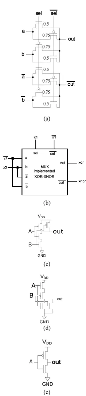
A compressor computes the sum of some 1-bit numbers. Fig. 1.a shows the general form of a 4:2 compressor, and Fig. 2 depicts an especial implementation of a 4:2 compressor based-on full-adder. Fig. 3 shows a low delay implementation [17]. Similar implementations can be found in [18-23].
(a)
(b)
Fig. 1. The Full-adder-based implementation of 4:2 precise compressor [15].
Fig. 2. A low delay implementation of 4:2 precise compressor [17].
In each of the 4:2 approximate compressors proposed in [15] and [16], the input carry was supposed to be zero. Therefore, the input carries were removed from their input list. Fig. 1.b shows the general form of a 4:2 compressor without input carry. Fig. 4 depicts two special implementations of the mentioned approximate compressors [15,16]. Table 1 shows the truth tables of these two circuits. According to these tables, the MSE of each of these two compressors is 0.25.
(a)
(b)
Fig. 3. The 4:2 approximate compressors without input carry proposed in (a) [15], and (b) [16].
Table 1. The Truth tables of 4:2 approximate compressors proposed in (a) [15], and (b) [16]. The difference column indicates the difference between the output of approximate and precise compressors.
(a) (b)
difference sum carry x1 x2 x3 x4 0 0 0 0 0 0 0 0 1 0 1 0 0 0 0 1 0 0 1 0 0 0 0 1 1 1 0 0 0 1 0 0 0 1 0 0 0 1 1 0 1 0 0 0 1 0 1 1 0 0 1 1 1 1 1 0 0 1 0 0 0 0 1 0 0 1 1 0 0 1 0 0 1 0 1 0 1 0 1 1 1 1 0 1 0 0 1 0 0 1 1 0 1 1 1 0 1 1 0 1 1 0 1 1 1 -2 0 1 1 1 1 1 difference sum carry x1 x2 x3 x4 1 1 0 0 0 0 0 0 1 0 1 0 0 0 0 1 0 0 1 0 0 -1 1 0 1 1 0 0 0 1 0 0 0 1 0 0 0 1 1 0 1 0 0 0 1 0 1 1 0 0 1 1 1 1 1 0 0 1 0 0 0 0 1 0 0 1 1 0 0 1 0 0 1 0 1 0 1 0 1 1 1 1 0 1 -1 1 0 0 0 1 1 0 1 1 1 0 1 1 0 1 1 0 1 1 1 -1 1 1 1 1 1 1
Fig. 4. Partial product matrix of an 8-bit multiplier
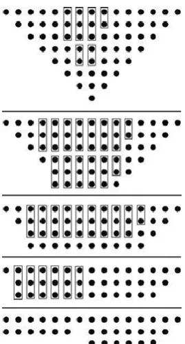
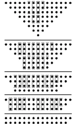
Fig. 6 shows an 8-bit Dadda multiplier constructed by only some half and full-adders, and Fig. 7 depicts an 8-bit Dadda multiplier constructed by some half and full-adders and some 4:2 compressors. Each rectangle represents a half adder, full adder or 4:2 compressor. Each of half adder, full adder and 4:2 compressor output a summation and a carry shown with two dots in the same column and the next column of the next stage, respectively.
As it can be seen, the former multiplier is performed in five stages while the successor multiplier is performed in three stages. In the two first stages of the successor multiplier shown in Fig. 7, Carry Save Adders (CSA) are used to decrease the eight rows of partial products to two rows, and then a CPA is used to compute the final result. In [15] and [16], in order to decrease the power consumption and delay of multiplier shown in Fig. 7, 4:2 approximate compressor was used instead of precise compressor. The delay of an 8-bit approximate Dadda multiplier constructed by using the traditional 4:2 approximate compressors [15, 16] is less than that of an 8-bit Dadda multiplier constructed by using 4:2 precise compressors. But, our experiments show that the delay of the former and 8-bit Dadda multiplier constructed by using only some half-adders and full-adders (3:2 precise compressors) does not differ. However, the number of transistors and the power consumption of the former multiplier is less than the successor multiplier.
In this paper, a novel 8-bit approximate multiplier is proposed based on three novel 4:2 approximate compressors which its delay and error is less than those of the Dadda multipliers constructed by the traditional 4:2 approximate compressors, and its delay is also less than that of the Dadda multiplier constructed by using only some half-adders and full-adders (3:2 precise compressors). To do so, each novel compressor is designed such that its output carry is independent of the output carry of its previous compressor in the multiplier. Therefore, the problem of carry propagation delay is eliminated and a fast multiplier is constructed.
Fig. 5. An 8-bit Dadda multiplier constructed by only some half and full-adders (each rectangle represents a half adder or full adder) [18].
Fig. 6. Using 4:2 compressors to construct an 8-bit multiplier (each rectangle represents a half adder, full adder or 4:2 compressor) [15].
3.
Our proposed multipliers
Before proposing our novel multipliers, its novel components, i.e. the novel compressors, must be introduced.
3.1 Our Proposed Compressors
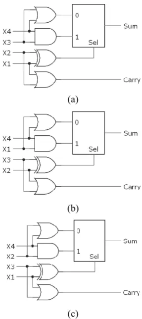
carry of the first proposed approximate compressor, shown in Fig. 8.a, is independent of x3 and x4 (third and fourth input). Therefore, if the output carry of an instance of this compressor is connected to the input x3 or x4 of another instance of this compressor, then the output carry of the successor can be produced even if the output carry of the former is not ready. Therefore, if the components of a CPA are such compressors, then this CPA does not have the carry propagation delay problem and consequently is very rapid.
(a)
(b)
(c)
Fig. 7. The three proposed 4:2 compressors.
Table 2. Truth tables of the three proposedcompressors.
3st compresor
2st compresor
1st compresor
Input differ. sum carry differ. sum carry differ. sum carry x1 x2 x3 x4 0 0 0 0 0 0 0 0 0 0 0 0 0 1 0 1 0 1 0 1 0 1 1 0 0 0 0 1 0 1 0 1 1 0 1 0 1 0 0 0 0 1 0 0 1 0 0 1 1 1 0 0 1 0 1 1 0 1 0 1 0 0 0 1 0 0 0 1 0 0 1 0 0 1 1 0 1 0 0 0 1 0 0 1 0 0 1 0 1 1 0 0 1 1 0 1 1 0 1 1 1 1 1 0 0 1 0 0 1 0 0 1 0 0 0 0 1 0 0 1 1 1 0 0 0 1 1 0 0 1 1 1 0 0 0 1 0 0 1 0 1 0 1 0 1 1 0 1 1 0 1 1 1 1 0 1 0 0 1 0 0 1 1 1 0 0 0 1 1 0 1 1 0 1 1 0 1 1 1 0 1 1 0 1 1 0 1 1 0 1 1 0 1 1 1 -1 1 1 -1 1 1 -1 1 1 1 1 1 1
3.2 Our Proposed CPA
Each of Fig. 9, Fig. 10 and Fig. 11 depicts a CPA which computes the sum of three 3-bit numbers, i.e. the
numbers A, B and C, by using different 4:2 approximate compressors, i.e. the compressors proposed in [15] and [16], and our proposed approximate compressors, respectively. In the CPA constructed by using our proposed compressors, the output carry of each of proposed compressor was connected to the fourth input (x4) of its successor compressor. Since the output carry of the proposed compressors is independent of the fourth input, the proposed CPA does not have the carry propagation delay problem. In the mentioned figures, the longest path of each CPA was shown with a thick line. As can be seen, the longest path of each CPA constructed by the compressors proposed in [15] or [16] is the path from input carry of CPA to the output carry of the last compressor, while the longest path of the CPA constructed by our proposed compressor is the path from an input of a compressor to the sum pin of its successor compressor. Meanwhile, the longest path to the output carry of the proposed CPA is the path from an input of its last compressor to that compressor output carry which is too short. This path was also depicted in Fig. 11 by a thick line.
Fig. 12 depicts the longest path in an 8-bit CPA constructed by the compressors proposed in [15] or [16], and Fig. 13 depicts the longest path in an 8-bit CPA constructed by the proposed compressors. As can be seen, the longest path of a CPA constructed by the compressors proposed in [15] and [16] becomes too longer for the bigger CPA, while the longest path of a CPA constructed by the proposed compressors is constant. Strictly speaking, regardless of the CPA length, the longest path of the CPA constructed by our proposed compressor is the path from an input of a compressor to the sum pin of its successor compressor.
Now, we determine the upper bound error of the proposed CPA. Consider the proposed CPA of the length t. If only t-th compressor of this CPA is approximate
compressor, the MSE of CPA becomes
2
14
16
t
,because the MSE of the proposed compressor is
4
0.25
16
. Therefore, an upper bound MSE for theproposed CPA is
2
14
2
21
16
t t
when allcompressors are approximate compressors, because the value of t-1 least significant bits of CPA is no more than
2
2
t
1
. To obtain this upper bound, we suppose thatthe value of t-1 least significant bits of CPA is always 2
2
t
1
more than or less than its real value, whileaccording to the truth table of our proposed compressor, the error probability of the proposed compressor is 0.25. Therefore, a tighter upper bound MSE for the proposed
CPA is
2
14
0.25
2
21
16
t t
Fig. 8. A CPA constructed by using the 4:2 approximate compressor proposed in [15] to compute the sum of three 3-bit numbers. The thick line shows its longest path.
Fig. 9. A CPA constructed by using the 4:2 approximate compressor proposed in [16] to compute the sum of three 3-bit numbers. The thick line shows its longest path.
Fig. 10. A CPA constructed by using our proposed 4:2 approximate compressor.
Fig. 11. A CPA constructed by using the 4:2 approximate compressor proposed in [15] or [16] to compute the sum of three 8-bit numbers. The thick line shows its longest path.
Fig. 12. A CPA constructed by using our proposed 4:2 approximate compressor to compute the sum of three 8-bit numbers. Each thick line can be the longest path.
3.3 Our
First
Proposed
Approximate
Multiplier
The approximate compressor shown in Fig. 8.a is used to construct our first approximate multiplier. Fig. 14 depicts this multiplier which is similar to the Dadda multiplier shown in Fig. 6. The number of stages of the proposed multiplier is one stage less than that of the former. At the last stage of the proposed multiplier, in order to obtain the summation of the three remaining rows of partial product, an especial CPA is used which was constructed by some half adders and some proposed approximate compressors. In each of the columns 2 and 15 of this CPA, a half adder is used, and in each of the columns 3 to 14, the first proposed compressor is used. Indeed, columns 3-14 of this CPA is our proposed CPA introduced in the previous sub-section which does not have the carry propagate delay problem. Meanwhile, one can use the approximate compressors only in the k least significant bits of the CPA to decrease its error. Fig. 15 shows this multiplier for k=8.
Fig. 14. The proposed multiplier for k=8. Each rectangle represents a half adder or a full adder. Sum of the last stage’s columns are computed using a CPA which is constructed by some half-adders, full-adders, and proposed 4:2 compressors.
3.4 Our Second Proposed Approximate
Multiplier
Consider the three proposed approximate compressors shown in Fig. 8. The only difference between these three compressors is the sequence of their inputs. For example, if the second input of compressor shown in Fig. 8.b is swapped with the third, the resulting circuit is the third compressor. Notice that changing the sequence of input of a precise compressor does not alter its output because a precise compressor computes the sum of its inputs, and its output is independent of the inputs sequence. But, this is not true for the approximate compressors.
As it can be seen in the truth Table 2, the output carry of each of the three proposed approximate compressors is independent of its fourth input. Therefore, if each of these three approximate compressors is used in the last stage of the proposed approximate multiplier to construct the CPA, the carry propagation delay problem is eliminated as long as the output carry of each of these compressors is connected to the fourth input of its next compressor. But, using each of the proposed compressors at each columns of CPA has different effect on the multiplier error and also affects the next column of CPA, because the output carry of each proposed compressor is connected to the next proposed compressor input. The proposed multiplier for an especial k was shown in the Fig. 15. To determine the type of approximate compressors for each columns 3 to k of CPA of multiplier to construct a multiplier with the least possible error, the following problem must be solved:
2 1 2 1
0 0
min
(
( , )
k k
i j
MSE
preciseMultiplication i j
2
( , ))
approximateMultiplication i j
Subject to: types of compressors of i-th column of CPA
of approximate multiplier
{1, 2,3},
i
3, 4,..., .
k
(1)
To solve the problem (1), each time a different combination of the three proposed compressors was used at the columns of CPA of multiplier, and the MSE of the constructed multiplier was calculated. Then, the best multiplier with the least MSE and the types of compressors used in it was registered in Table 3.
Table 3. The best compressor type of each columns of CPA of multiplier for different value of k obtained by solving the problem (1).
Column number 14 13 12 11 10 9 8 7 6 5 4 3 2 3 k 1 3 4 1 1 3 5 1 1 1 1 6 2 3 1 1 1 7 2 2 1 1 2 2 8 2 2 3 1 3 3 3 9 2 2 3 3 3 2 3 3 10 2 2 3 3 3 1 3 2 3 11 2 2 3 3 1 3 1 2 1 3 12 2 2 1 1 1 3 2 2 2 3 2 13 1 2 3 1 3 1 1 3 2 3 1 1 14
If the k in the problem (1) is a big number, the number of combinations of compressors types for the columns 3 to k of CPA of an 8-bit multiplier becomes a big number. For example, the number of combinations of compressors types for k=14 is equal to 3(14-2)=531,441.
4.
Simulations
In this section the proposed multipliers are compared with ten other multipliers: truncated1 [7], truncated2 [8], truncated3 [9], LOA [5], Momeni [15], Ma [16], Liu [13,14], Kulkani [11], Accurate3:2 (the Dadda multiplier constructed by 3:2 precise compressors), and Accurate4:2 (the Dadda multiplier constructed by 4:2 precise compressors).
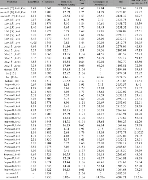
Table 4 shows the MSE, the delay, the number of transistors, and the product of delay and the number of transistors (PDT) of each multiplier. This table also shows the percentages of delay improvement, the percentages of the number of transistors improvement, the percentages of PDT improvement for each multiplier with respect to the multiplier Accurate3:2. According to this table, for each k, the MSE of the second approximate proposed multiplier is less than that of the first approximate proposed multiplier. To compute the MSE, each multiplier was simulated in MATLAB, and for computing the delay and the number of transistors needed to construct each multiplier, each multiplier was simulated in HSPICE at 16 nm CMOS technology based on the best gates of [21] (See Fig. 16). Working voltage
and the temperature were supposed to be 3.3v and 27 degrees centigrade.
According to Table 4, when the multiplication operands are supposed to be selected from a uniform distribution,
• For each k, the MSE of the second approximate proposed multiplier is less than that of the first approximate proposed multiplier.
For k=3,4,…,12, the error and the delay of the second proposed method are less than those of the traditional 4:2 approximate compressor-based multipliers.
Table 5(a) (b)
• Table 1 shows the least error and delay improvement of the second proposed method with respect to the traditional 4:2 approximate compressor-based multipliers.
Table 4. Comparison of different multipliers.
Multiplier Log(MSE) #Transistors
#Transistors impr. with respect to Acc3:2
Delay (ns)
Delay improvement with respect to
Accurate3:2
PDT respect to Acc3:2 PDT impr. with
truncated1]7[,P=11,K=4 24.2 14.2 22422 1427 1848. 2478428 34422 truncated2]8[,P=11,K=4 2423 1722 12422 1474 1.422 2278422 24427 truncated3]2[,P=8,k=4 .411 1382 2844. 1443 24441 2121437 .2477
LOA]4[, k=3 2417 1222 1474 1421 7412 3233474 8482
LOA]4[, k=4 244. 187. 3412 148. 12421 3.41472 13432 LOA]4[, k=5 14.2 18.. .424 1472 1.4.3 3241442 184.1
LOA]4[, k=6 2421 1822 4472 1422 17484 328.422 22421 LOA]4[, k=7 2472 1722 7413 1421 21422 2822412 27424 LOA]4[, k=8 34.2 1772 84.7 144. 24422 2732417 314.. LOA]4[, k=9 ..24 17.. 2482 14.. 32428 2412474 32424
LOA]4[, k=10 .422 1718 11412 1.32 34424 2278422 .2483 LOA]4[, k=11 4424 1222 12441 12. 32442 212742. .7413
LOA]4[, k=12 4482 1222 13484 1.14 ..444 1223447 42423 LOA]4[, k=13 2432 12.2 14422 2422 41472 1222417 42412
LOA]4[, k=14 2484 121. 1244. 248. 42422 1322472 24482 LOA]4[, k=15 7438 1488 17482 2422 22422 1123481 72432
Momeni]14[ 7421 1442 12484 2.22 2 312.428 12484
Ma]12[ 2427 1282 12482 2.22 2 3.7.43. 12482
Liu [13,14] 2412 222. .424- 1412 .44.2 227.477 .2422
Kulkani [11] 2481 1412 21482 2432 12477- 3413488 11483
Proposed1,k=3 2422 1228 143. 1421 7414 3242447 84.2
Proposed1, k=4 1412 1882 2428 1472 13423 3372473 14437
Proposed1, k=5 1472 1842 .423 1473 14422 3227422 12422
Proposed1, k=6 2431 1832 4437 1424 12442 3232412 23421
Proposed1, k=7 3423 182. 2472 1422 22422 2822417 274.3
Proposed1, k=8 3422 1778 8422 1.41 22422 2284422 32421
Proposed1, k=9 .412 1742 24.1 1.37 33412 2.14432 32432
Proposed1, k=10 .483 1722 12474 1.31 32418 2222422 .342.
Proposed1, k=11 44.2 1722 12422 1.21 .1417 2222421 .8428
Proposed1, k=12 2423 127. 134.. 1.22 .84.1 1772422 4443.
Proposed1, k=13 2442 12.8 1.478 2.21 4442. 1422427 22422
Proposed1, k=14 7418 1222 12413 2424 2841. 122.428 73428
Proposed2, k=3 2424 1228 143. 1421 7414 3242447 84.2
Proposed2, k=4 1412 1882 2428 1472 13423 3372473 1443727
Proposed2, k=5 1471 1842 .423 1473 14422 3227422 12422
Proposed2, k=6 2431 1832 4437 1424 12442 3232412 23421
Proposed2, k=7 2424 182. 2472 1422 22422 2822417 274.3
Proposed2, k=8 3442 1778 8422 1.41 22422 2284422 32421
Proposed2, k=9 .422 1742 24.1 1.37 33412 2.14432 32432
Proposed2,k=10 .422 1722 12474 1.31 32418 2222422 .342.
Proposed2, k=11 4428 1722 12422 1.21 .1417 2222421 .8428
Proposed2, k=12 4482 127. 134.. 1.22 .84.1 1772422 4443.
Proposed2, k=13 24.8 12.8 1.478 2.21 4442. 1422427 22422
Proposed2, k=14 742. 1222 12413 2424 2841. 122.428 73428
Accurate3:2 - 123. 2 2.22 2 3284432 2
-Table 5. The least error and delay improvement of the second proposed method with respect to the traditional 4:2 approximate compressor-based multipliers (%).
The least error improvement
(%) The least delay improvement (%)
K=3 89.25 7.15
K=4 80.89 13.03
K=5 71.83 15.63
K=6 61.95 19.60
K=7 51.35 22.20
K=8 42.00 26.70
K=9 32.52 33.10
K=10 22.65 36.19
K=11 13.06 41.17
K=12 2.96 48.41
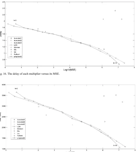
Fig. 17 shows the delay of each multiplier versus its MSE. There is a trade off between the delay and the MSE of a multiplier. The less the delay of a multiplier, the more its MSE. But, according to this Fig., the second proposed multiplier has less delay than that of the other multipliers with the same MSE level, except the LOA for some k, or the second proposed multiplier has less MSE than that of the other multipliers with the same delay level, except the LOA for some k. The second proposed multiplier for k=8,9,…,14 has also less delay than that of the LOA with the same MSE level.
Fig. 18 shows the PDT of each multiplier versus its MSE. According to this Fig., the second proposed multiplier has less PDT than that of the other multipliers with the same MSE level, except LOA for some k and the truncated multipliers, or the second proposed multiplier has less MSE than that of the other multipliers with the same PDT level, except LOA for some k and the truncated multipliers. The second proposed multiplier for k=8,9,11,…,14 has also less PDT than that of LOA with the same MSE level.
(a)
(b)
(c)
(d)
(e)
Fig. 16. The delay of each multiplier versus its MSE.
Fig. 17. The PDT of each multiplier versus its MSE.
5.
Applications
5.1 Image Blending
Fig. 19 shows an application of multiplication in image processing. The right blended 8-bit image in this Fig. was obtained by peer-to-peer pixel multiplication of the two left 8-bit images using a precise multiplier and truncation of the 16-bit result to 8-bit. In this sub-section, the approximate multipliers are used to blend the two right images. Table 6 shows the PSNR of the blended
images for each multiplier. The PSNR formulation is as follows:
210
10log
Peak Signal Value MSE
PSNR
(2)
(a) (b) (c) Fig. 18. Blended images using precise multiplier (a) the first image, (b) the second image, (c) Blended image.
Fig. 20 shows the delay of each multiplier versus the negative of its PSNR for the image blending. There is a trade off between the delay and the -PSNR of a multiplier. The less the delay of a multiplier, the more its -PSNR. But, according to this Fig., the second proposed multiplier has less delay than that of the other multipliers with the same PSNR level, except LOA for some k, or the second proposed multiplier has less -PSNR than that of the other multipliers with the same delay level, except LOA for some k. The second proposed multiplier for k=8,9,…,14 has also less delay than that of LOA with the same PSNR level.
Table 6. PSNR of blended images for different approximate multipliers.
Multiplier PSNR Multiplier PSNR
truncated1
]
7
[
,p=11,k=4
71432
Proposed1, k=572422
truncated2]
8
[
,p=11,k=4
74481
Proposed1, k=672423
truncated3]
2
[
,p=8,k=4
44434
Proposed1, k=724478
LOA]
4
[
, k=32.4..
Proposed1, k=842423
LOA]
4
[
, k=422428
Proposed1, k=94.432
LOA]
4
[
, k=582418
Proposed1, k=10.7482
LOA]
4
[
, k=672412
Proposed1, k=11.1427
LOA]
4
[
, k=722442
Proposed1, k=1234423
LOA]
4
[
, k=821442
Proposed1, k=1322421
LOA]
4
[
, k=9444..
Proposed1, k=142.422
LOA]
4
[
, k=10.243.
Proposed2, k=382472
LOA]
4
[
, k=11.3412
Proposed2,k=483473
LOA]
4
[
, k=1237412
Proposed2,k=577472
LOA]
4
[
, k=1333422
Proposed2,k=67242.
LOA]
4
[
, k=142.422
Proposed2,k=722
43.
LOA]
4
[
, k=151242.
Proposed2,k=821422
Momeni]
14
[
27482
Proposed2,k=9444..
Ma]
12
[
.2428
Proposed2,k=10.24..
Liu [13,14]3342.
Proposed2,k=11.3478
Kulkani [11]22432
Proposed2,k=1237422
Proposed1, k=382423
Proposed2,k=1331428
Proposed1, k=48.432
Proposed2,k=1428423
Truncated1
]
7
[
Truncated2]
8
[
Truncated3]
2
[
LOA
]
4
[
,k=3 LOA]
4
[
,k=4 LOA]
4
[
,k=5LOA
]
4
[
,k=6 LOA]
4
[
,k=7 LOA]
4
[
,k=8LOA
]
4
[
,k=9 LOA]
4
[
,k=10 LOA]
4
[
,k=11LOA
]
4
[
,k=12 LOA]
4
[
,k=13 LOA]
4
[
,k=14LOA
]
4
[
, k=15 Momeni]
14
[
Ma]
12
[
Liu [13,14] Kulkani [11] Proposed1, k=3
Proposed1,k=4 Proposed1,k=5 Proposed1,k=6
Proposed1,k=7 Proposed1,k=8 Proposed1,k=9
Proposed1,k=10 Proposed1,k=11 Proposed1,k=12
Proposed1,k=13 Proposed1,k=14 Proposed2,k=3
Proposed2,k=4 Proposed2,k=5 Proposed2,k=6
Proposed2,k=7 Proposed2,k=8 Proposed2,k=9
Proposed2,k=10 Proposed2,k=11 Proposed2,k=12
Proposed2,k=13 Proposed2,k=14 Accurate3:2
Fig. 20. The blended images obtained by different approximate multipliers.
Fig. 21. The PDT of each multiplier versus the negative of its PSNR for the image blending.
5.2 Image Compression
In this section, the proposed multiplier is used in the JPEG algorithm for lossy image compression. The block diagram of JPEG algorithm was shown in Fig. 23. In this algorithm, first, the image is encoded to the color coding YUV. Then, their 8×8 blocks of each channel Y, U and V shown by f is transformed from the time domain into the frequency domain using Discrete Cosine Transform (DCT) [24] to obtain a new 8×8 blocks named F. the DCT formulation is as follows:
,
( ) ( )
4
C u C v
F u v
7 7
0 0
2 1
2
1
cos
cos
( , )
16
16
i j
i
u
j
u
f i j
(3)
where
2
0,
( )
2
1
.
if u
c u
otherwise
In this paper, integer value version of this transformation [25] is used which is as follows:
7 7
0 0
1
( , )
( , ) ( , ),
1024
i jF u v
z i j f i j
(4)where
( , )
(1024
( ) ( )
4
C u C v
z i j
round
2 1
2
1
cos
cos
)
16
16
i
u
j
u
is an 8-bitinteger value.
Fig. 22. Block diagram of JPEG algorithm [24].
(a) (b) (c)
(d) (e) (f)
Fig. 23. Six benchmark images.
Truncated1]7[ Truncated2]8[ Truncated3]2[
LOA]4[,k=3 LOA]4[,k=4 LOA]4[,k=5
LOA]4[,k=6 LOA]4[,k=7 LOA]4[,k=8
LOA]4[,k=9 LOA]4[,k=10 LOA]4[,k=11
LOA]4[,k=12 LOA]4[,k=13 LOA]4[,k=14
LOA]4[,k=15 Momeni]14[ Ma]12[
Liu [13,14] Kulkani [11] Proposed1,k=3
Proposed1, k=4 Proposed1,k=5 Proposed1, k=6
Proposed1,k=7 Proposed1, k=8 Proposed1, k=9
Proposed1, k=10 Proposed1,k=11 Proposed1, k=12
Proposed1, k=13 Proposed1,k=14 Proposed2,k=3
Proposed2, k=4 Proposed2,k=5 Proposed2, k=6
Proposed2, k=7 Proposed2,k=8 Proposed2, k=9
Proposed2,k=10 Proposed2,k=11 Proposed2,k=12
Proposed2, k=13 Proposed2, k=14 Accurate3:2
Table 7. PSNR or similarity amount of the original images and the corresponding decompressed images for different multipliers.
Multiplier PSNR of each image type Mean of PSNR
PSNR mean improvement with respect to
Accurate3:2
a b c d e f
truncated1]7[, P=11,K=4 24422 24422 2442. 24432 24424 24433 24432 1.4.777
truncated2]8[, P=11,K=4 72423 73422 72412 7347. 73421 73448 73444 342722
truncated3]2[, P=8,k=4 4.4.2 44472 .2421 .2488 .2422 44432 .2487 3.428
LOA]4[, k=3 7.422 744.8 83424 724.1 74418 72428 72422 2412
LOA]4[, k=4 7342. 744.1 82422 72432 74412 72422 72417 242. LOA]4[, k=5 734.1 7.47. 72421 744.2 7.4.2 74412 74432 1434
LOA]4[, k=6 71487 72442 744.2 73422 72482 72422 73414 .422
LOA]4[, k=7 27423 28414 22444 2847. 28414 28422 28484 2483 LOA]4[, k=8 214.. 21472 22412 22412 214.8 21481 2242. 17422
LOA]4[, k=9 44473 44428 42418 44471 4242. 44472 42441 24428
LOA]4[, k=10 .2442 .2471 .2488 .2472 42422 .2442 42422 33421
LOA]4[, k=11 .3473 ..4.8 ..412 ..42. ..441 ..422 .4422 .2472 LOA]4[, k=12 38428 32432 32473 32474 32444 32418 32483 .7483
LOA]4[, k=13 3.42. 32414 34411 32418 34478 34442 32438 4243. LOA]4[, k=14 22487 32444 3142. 31481 31422 324.3 31441 48473
LOA]4[, k=15 22424 284.2 28442 32427 284.3 27427 224.2 214.2 Momeni]14[ 234.. 23422 22437 22437 2247. 23422 22424 2242.
Ma]12[ .2422 .8422 .2422 41428 .2471 .8427 .2422 3444.
Liu [13,14] .1482 .242. .3414 .3424 .2422 .2423 .3422 .3427
Kulkani [11] 32428 .2414 ..4.. .3442 .2427 .2478 .2422 .3481
Proposed1, k=3 73422 744.2 82482 72432 74413 74422 72417 242.
Proposed1, k=4 73472 74422 81434 74421 7.482 74423 74472 2482
Proposed1, k=5 72477 73484 77427 7.4.2 73422 7.433 7.422 247.
Proposed1, k=6 72432 72421 7342. 71421 7142. 71433 714.3 24..
Proposed1, k=7 2242. 22434 27427 22432 22482 22433 22444 1248.
Proposed1, k=8 47417 47421 474.3 47432 47423 47427 4743. 2.422
Proposed1, k=9 414.2 41442 4142. 414.2 41447 41441 41472 32428
Proposed1, k=10 .4.33 .44.2 .4423 .4442 .44.. .4443 .4472 .2414
Proposed1, k=11 32442 32442 32482 32422 32482 32442 32423 .8412
Proposed1, k=12 37434 374.2 38421 37488 38412 37432 37473 42448
Proposed1, k=13 32442 33423 3.414 33422 3.418 33414 33472 44473
Proposed1, k=14 22448 22474 214.2 24412 22422 214.3 21421 71432
Proposed2, k=3 73427 744.. 83422 72434 74412 72422 72421 2418
Proposed2, k=4 73472 74418 81442 72423 7.422 74471 74482 2472
Proposed2, k=5 73411 7.428 78442 7..21 7.422 7.427 7.422 2418
Proposed2, k=6 71432 72428 73482 724.. 71428 72423 72431 4422
Proposed2, k=7 27422 28422 28482 28442 28423 28428 28424 12421
Proposed2, k=8 48422 48414 48432 48412 48421 48422 48412 23488
Proposed2, k=9 42424 42432 424.2 424.3 424.2 42432 424.2 31424
Proposed2, k=10 .2417 .2431 .244. .24.1 .242. .2438 .24.8 32412
Proposed2, k=11 .2421 .241. .2442 .2434 .2443 .2427 .242. .7422
Proposed2, k=12 3.422 3.414 3.44. 3347. 3.473 3.421 3.423 44417
Proposed2, k=13 27422 2842. 22423 28447 274.. 2843. 28424 23422
Proposed2, k=14 21422 21432 214.3 24412 22423 22442 22421 72422
Accurate3:2 7.422 7444. 83424 72.49 7442. 72412 72432 2
Fig. 26 shows the delay of each multiplier versus the negative of its PSNR for the image compression. There is a trade off between the delay and the -PSNR of a multiplier. The less the delay of a multiplier, the more its -PSNR. But, according to this Fig., the second proposed multiplier has less delay than that of the other multipliers
section IV the MSE was calculated based on the all of 8-bit multiplier truth table states and thus multiplication operands were supposed to be from a uniform distribution, while in this section the PSNR (which related directly to MSE) was computed based on some of multiplier truth table states. These states depend on multiplication operands, pixels values, histogram, or data distribution of each image. Therefore, one can obtain different result for some other images probably. If it is supposed that the multiplication operands in the JPEG compression have a uniform distribution, then the result will be the same as what were shown in Table 4 not what where shown in Table 7.
Fig. 27 shows the PDT of each multiplier versus the negative of its PSNR. According to this Fig., the second proposed multiplier has less PDT than that of the other multipliers with the same PSNR level, except LOA for some k and the truncated multipliers, or the second proposed multiplier has less -PSNR than that of the other multipliers with the same PDT level, except LOA for some k and the truncated multipliers. The second proposed multiplier for k=4,6,7 has also less PDT than that of LOA with the same PSNR level.
6.
Conclusion
In this paper, a novel 8-bit approximate multiplier based on three novel 4:2 approximate compressors was proposed which its delay and error was less than those of the multipliers constructed by traditional 4:2 approximate compressors, and its delay is also less than that of an 8-bit multiplier constructed by using 3:2 precise compressors. To do so, each novel compressor was designed such that its output carry was independent of some of its inputs.
One of these inputs was connected to the output carry of its previous compressor in the CPA of multiplier. Therefore, the problem of carry propagation delay of multiplier’s CPA was eliminated and a fast multiplier was constructed. This was the first proposed multiplier. To obtain the most accurate multiplier, the best compressor of the three proposed compressors for each multiplier’s columns is determined using the genetic algorithm. The constructed multiplier called the second proposed multiplier. Meanwhile, for more error reduction, the approximate compressors were used only at the k least significant columns of multiplier. The proposed multipliers were used for image blending and image compression.
According to the simulations results (Table 4), when the multiplication operands are supposed to be selected from a uniform distribution, for each k, the MSE of the second approximate proposed multiplier is less than that of the first approximate proposed multiplier. For k=3,4,…,12, the error and the delay of the second proposed method are less than those of the traditional 4:2 approximate compressor-based multipliers (See Table 5 for detail). Meanwhile, the second proposed multiplier has less delay than that of the other multipliers with the same MSE level, except the LOA for some k, or the second proposed multiplier has less MSE than that of the other multipliers with the same delay level, except the LOA for some k. The second proposed multiplier for k=8,9,…,14 has also less delay than that of the LOA with the same MSE level.
Fig. 26. The PDT of each multiplier versus the negative of its PSNR for the images compression.
References
[1] J. Liang, J. Han, and F. Lombardi, "New metrics for the reliability of approximate and probabilistic adders," IEEE Transactions on Computers, vol. 62, pp. 1760-1771, 2013.
[2] V. Gupta, D. Mohapatra, S. P. Park, A. Raghunathan, and K. Roy, "IMPACT: imprecise adders for low-power approximate computing," in Proceedings of the 17th IEEE/ACM international symposium on Low-power electronics and design, 2011, pp. 409-414.
[3] S. Cheemalavagu, P. Korkmaz, K. V. Palem, B. E. Akgul, and L. N. Chakrapani, "A probabilistic CMOS switch and its realization by exploiting noise," in IFIP International Conference on VLSI, 2005, pp. 535-541.
[4] A. B. Kahng and S. Kang, "Accuracy-configurable adder for approximate arithmetic designs," in Proceedings of the 49th Annual Design Automation Conference, 2012, pp. 820-825.
[5] H. R. Mahdiani, A. Ahmadi, S. M. Fakhraie, and C. Lucas, "Bio-Inspired Imprecise Computational Blocks for Efficient VLSI Implementation of Soft-Computing Applications," IEEE TRANSACTIONS ON CIRCUITS AND SYSTEMS, vol. 57, pp. 850-862, 2011.
[6] K.-J. Cho, K.-C. Lee, J.-G. Chung, and K. K. Parhi, "Design of low-error fixed-width modified booth multiplier," IEEE Transactions on Very Large Scale Integration (VLSI) Systems, vol. 12, pp. 522-531, 2004.
[7] M. J. Schulte and E. E. Swartzlander, "Truncated multiplication with correction constant [for DSP],"
in VLSI Signal Processing, VI, 1993., [Workshop on], 1993, pp. 388-396.
[8] E. J. King and E. E. Swartzlander, "Data-dependent truncation scheme for parallel multipliers," in Signals, Systems & Computers, 1997. Conference Record of the Thirty-First Asilomar Conference on, 1997, pp. 1178-1182 vol.2.
[9] H.-J. Ko and S.-F. Hsiao, "Design and Application of Faithfully Rounded and Truncated Multipliers With Combined Deletion, Reduction, Truncation, and Rounding," IEEE TRANSACTIONS ON CIRCUITS AND SYSTEMS, vol. 58, pp. 304-308, 2011.
[10] Harish Rao. B and R. K. V, "IMPLEMENTATION
OF 8X8 DADDA MULTIPLIER USING
APPROXIMATE COMPRESSION FOR IMAGE ENHANCEMENT," International Journal of Advances in Engineering Research, vol. 10, pp. 70-81, 015.
[11] P. Kulkarni, P. Gupta, and M. Ercegovac, "Trading accuracy for power with an underdesigned multiplier architecture," in VLSI Design (VLSI Design), 2011 24th International Conference on, 2011, pp. 346-351.
[12] D. Kelly, B. Phillips, and S. Al-Sarawi, "Approximate signed binary integer multipliers for arithmetic data value speculation," 2009.
[13] C. Liu, "Design and analysis of approximate adders and multipliers," 2014.
[15] A. Momeni, H. Jie, P. Montuschi, and F. Lombardi, "Design and Analysis of Approximate Compressors for Multiplication," Computers, IEEE Transactions on, vol. 64, pp. 984-994, 2015.
[16] J. Ma, K. Man, T. Krilavicius, S. Guan, and T. Jeong, "Implementation of High Performance Multipliers Based on Approximate Compressor Design," presented at the International Conference on Electrical and Control Technologies Yichang, China, 2011.
[17] C.-H. Chang, J. Gu, and M. Zhang, "Ultra low-voltage low-power CMOS 4-2 and 5-2 compressors for fast arithmetic circuits," IEEE Transactions on Circuits and Systems I: Regular Papers, vol. 51, pp. 1985-1997, 2004.
[18] P. Behrooz, "Computer arithmetic: Algorithms and hardware designs," Oxford University Press, vol. 19, pp. 512583-512585, 2000.
[19] J. Gu and C.-H. Chang, "Ultra low voltage, low power 4-2 compressor for high speed multiplications," in Circuits and Systems, 2003. ISCAS'03. Proceedings of the 2003 International Symposium on, 2003, pp. V-V.
[20] M. Margala and N. G. Durdle, "Low-power low-voltage 4-2 compressors for VLSI applications," in Low-Power Design, 1999. Proceedings. IEEE Alessandro Volta Memorial Workshop on, 1999, pp. 84-90.
[21] K. Prasad and K. K. Parhi, "Low-power 4-2 and 5-2 compressors," in Signals, Systems and Computers, 2001. Conference Record of the Thirty-Fifth Asilomar Conference on, 2001, pp. 129-133. [22] M. D. Ercegovac and T. Lang, Digital arithmetic:
Elsevier, 2004.
[23] D. Baran, M. Aktan, and V. G. Oklobdzija, "Energy efficient implementation of parallel CMOS multipliers with improved compressors," in Low-Power Electronics and Design (ISLPED), 2010 ACM/IEEE International Symposium on, 2010, pp. 147-152.
[24] G. K. Wallace, "The JPEG still picture compression standard," IEEE transactions on consumer electronics, vol. 38, pp. xviii-xxxiv, 1992.
[25] K. K. Parhi, VLSI digital signal processing systems: design and implementation: John Wiley & Sons, 2007.
![Fig. 3 shows a low delay implementation [17]. Similar](https://thumb-us.123doks.com/thumbv2/123dok_us/8439328.1700753/2.595.363.481.383.623/fig-shows-low-delay-implementation-similar.webp)
![Table 1. The Truth tables of 4:2 approximate compressors proposed in (a) [15], and (b) [16]](https://thumb-us.123doks.com/thumbv2/123dok_us/8439328.1700753/3.595.92.247.80.266/table-truth-tables-approximate-compressors-proposed-b.webp)
![Fig. 8. A CPA constructed by using the 4:2 approximate compressor proposed in [15] to compute the sum of three 3-bit numbers](https://thumb-us.123doks.com/thumbv2/123dok_us/8439328.1700753/6.595.63.430.559.757/fig-constructed-using-approximate-compressor-proposed-compute-numbers.webp)
![Fig. 11. A CPA constructed by using the 4:2 approximate compressor proposed in [15] or [16] to compute the sum of three 8-bit numbers](https://thumb-us.123doks.com/thumbv2/123dok_us/8439328.1700753/7.595.337.502.366.622/fig-constructed-using-approximate-compressor-proposed-compute-numbers.webp)