Infogain Publication (Infogainpublication.com) ISSN : 2454-1311
Modeling of EDM electrodes for development of
LPOT turbine rotor and optimization of
parameters for attenuate portioned electrode by
Taguchi based Grey Relational Analysis
Shyam Sankar
1,Jessin T.A
2,M.Vittal Naik
31Department of Mechanical Engg, TKM College of Engg, Kollam, Kerala, India 2
Asst. Professor , Department of Mechanical Engg, TKM College of Engg, Kollam, Kerala, India 3
Scientist/Engineer, Liquid Propulsion Systems Center, Thiruvananthapuram, Kerala, India
Abstract— Launch vehicle requires high thrust during lift off. Semi-cryogenic engine using liquid oxygen (LOX) as the oxidiser and kerosene (earth storable) as the fuel, produces thrust around 2000kN. LOX is pumped by Low Pressure Oxidiser Turbo pump (LPOT) to level required for cavitation free operation of the Main Oxidiser Pump (MOP). Inconel 718, the material for LPOT turbine rotor has High strength thermal resistance (HSTS), ignition resistance and property of work hardening, which refers to strengthening of metal by plastic deformation (after the machining pass). The conventional machining processes cannot be adopted to produce complex shapes with high surface finish and accuracy. The non conventional machining technique like EDM is preferred. Due to the closed tip nature of the rotor die sinking EDM is preferred over wire EDM. The LPOT turbine has two rows of rotor blades; 100 symmetric blades and 105 asymmetric blades. The modeling of the EDM electrodes is done in CAD and the trial manufacturing of the electrodes for developing symmetric blade of turbine rotor is carried out. One of the electrode is having a section with 0.4mm thickness. The EDM parameters are optimized for attenuate/thin portioned electrode using Taguchi based Grey Relation Analysis. The most significant parameter using ANOVA is found out. Confirmation test are also performed with optimum parameter combination and an improvement of machining parameter is obtained.
Keywords— Grey RelationalAnalysis, Inconel 718, LPOT, Taguchi Design of Experiment.
I. INTRODUCTION
Semi-cryogenic engine operating with Liquid Oxygen (LOX) and kerosene propellant delivers a vacuum thrust of 2000kN, is good for liftoff. LOX stored at a temperature of 91 K and pressure 0.5 MPa is pumped by Low Pressure Oxidiser Turbo pump (LPOT) (mounted at the Engine inlet) to Main Oxidizer Pump (MOP) at the required pressure of
1.72 MPa to ensure cavitation free operation. LPOT turbine is driven by oxidizer rich hot gas taped from Main Turbine (MT) outlet. The Pre Burner (PB) generates and supplies hot gas required for driving the MT. Hot gas, after driving the LPOT turbine, joins LOX stream at LPOT pump outlet to get condensed before reaching MOP inlet. The LPOT consist of inducer, two sets of rotor blades. The stators will guide the hot gas from first rotor exit to the second rotor. The material for LPOT should have good ignition resistance and high temperature strength due to the flow of oxidizer rich gas. Nickel base alloys, cobalt base alloys, iron base alloys and titanium alloys are the common heat resistant alloys. Among these nickel based super alloy is extremely useful in gas turbine, space vehicles [18], aircraft, nuclear reactors, submarine, petrochemical equipments and other high temperature applications fields. Inconel 718, a nickel based super alloy, is a precipitation-hardenable nickel chromium alloy containing significant amounts of iron, niobium, and molybdenum along with lesser amounts of aluminum and titanium. It combines corrosion resistance and high strength with outstanding weldability, including resistance to post weld cracking. The alloy has excellent creep-rupture strength at temperatures up to 700° C (1300°F). Due to its excellent mechanical and metallurgical properties this alloy finds extensive application in gas turbines, rocket motors, spacecraft, nuclear reactors, pumps and tooling [16]
Infogain Publication (Infogainpublication.com) ISSN : 2454-1311 are generated, which machines all the blades simultaneously
reducing the time and effort. Constraints associated with clustered electrodes are position of the electrode with respect to the job which determines the accuracy and dimension of the rotor, thickness of electrode blade. While modeling, one of the electrode is having thin/attenuate portion, so considering the effort and cost involved, its safety is of concern. This study focuses on the attenuate portion of electrode and investigate machining performance on inconel 718 by EDM and optimizing the parameters using Taguchi based Grey Relational Analysis.
Pushpendra S Bhaarti et.al.(2010) [1] , conducted study on machining characteristics of Inconel 718 during die sinking electric discharge machining process with copper as tool electrode applying taguchi methodology following L36 orthogonal array. Various factors like shape factor, pulse on time, discharge current, duty cycle, gap voltage, flushing pressure and tool electrode lift time and performance measures like material removal rate, surface roughness and tool wear rate were considered. ANOVA test was also carried out. N. Pragadish , M. Pradeep Kumar (2016) [2] used modified tool design to drill holes in the dry EDM process. Experiments were conducted on AISI D2 steel using a copper electrode as the tool. Taguchi’s L27 orthogonal array was used to design the experiments. The input parameters were discharge current (I), pulse on time (T ON), voltage (V), pressure (P) and tool rotational speed (N) chosen. The optimum levels were found using the grey relational analysis and statistically analysed by using the ANOVA test. Dr. Rajeev kumar garg, Kuldeep ojha (2011) [3] conducted a review on the research relating to EDM electrode design and its manufacturing for improving and optimizing performance measures, reducing time and cost of manufacturing . P.Narender Singh , K. Raghukandana, B.C. Pai(2004) [4] conducted multi-response optimization by considering the process parameters; metal removal rate (MRR), tool wear rate (TWR), taper (T), radial overcut (ROC), and surface roughness (SR) on electric discharge machining (EDM) of Al–10%SiCP using orthogonal array (OA) with Grey relational analysis and the optimum parameters were found out. Włodzimierz Wilk, M.Sc., Jacek Tota(2007) [6] studied about the modern technology of turbine blade machining. They discussed about abbrasive machining technology ,other unconventional techniques for the machining of turbine blades, current trends of using HSCD grinding method and applications of the different types of the abrasive tools for the turbine parts production. Kanthasamy M.et.al. [7] reviewed about semi-cryogenic engine and carried out different experiments , hot and cold testing and its results. Also the features of the different hardware in the semi-cryo engine were discussed.
II. MODELING AND GENERATION OF ELECTRODES
The LPOT turbine rotor is basically a closed tip rotor which makes it only accessible from the side of the rotor. Inconel 718 is material used for the rotor manufacturing which is difficult to be machined by conventional machining methods. EDM is employed specifically the die sinking EDM. The modeling of the rotor is the first step in the generation of tool for the development of LPOT turbine rotor. The LPOT turbine rotor has two sets of blades, symmetric and asymmetric. The symmetric set has 100 blades while asymmetric has 105 blades. The rotor is modeled in NX CAD software. The commands used are extrude, pattern geometry, revolve etc.
Fig.1: LPOT Turbine rotor modeled in NX CAD
The EDM electrode cluster is generated from the rotor model using commands like wave geometry linker , create datum planes, offset surface, trim body, law extension, pattern geometry, ruled, sew, extrude, unite etc.
The generation of tool from the rotor model is done by providing spark gap of 0.2mm which is given as offset in the modeling software. The first electrode for the development of LPOT turbine rotor is shown in fig 2. Different commands stated above are used to generate the electrodes. The hole in the electrode is provided for the setting of electrode with respect to the job, hole is also provided in the workpiece.
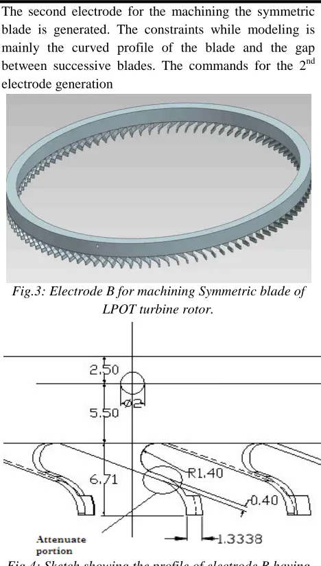
Infogain Publication (Infogainpublication.com) ISSN : 2454-1311 The second electrode for the machining the symmetric
blade is generated. The constraints while modeling is mainly the curved profile of the blade and the gap between successive blades. The commands for the 2nd electrode generation
Fig.3: Electrode B for machining Symmetric blade of LPOT turbine rotor.
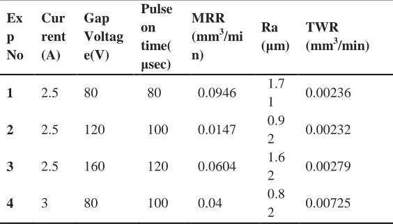
Fig.4: Sketch showing the profile of electrode B having an attenuate/ thin section.
Fig 4 shows the attenuate or thin portion of the electrode which is critical section of the electrode. There is a concern about how the electrode performs and what are the possible parameters like current, voltage, pulse on time etc which can be given to the electrode. A study is conducted by considering the attenuate portion with assumptions to find the tool wear rate, surface roughness and the material removal rate and optimize the parameters of EDM to get optimum tool wear rate, surface roughness and material removal rate.
The electrode A and B modeled is used for the manufacturing of only one half of the symmetric blade. The replica of the two is required to attain complete profile of the symmetric blade. Thus in total 4 electrodes are required for manufacturing the symmetric blades of LPOT turbine rotor. Another challenge in the development of rotor is that the machining of symmetric blades that are at side closer to the asymmetric blade require special holding mechanisms and the electrodes should be carefully maneuvered such that it will not collide with the 2nd row of rotor blades.
Fig.5: Electrode C for machining Asymmetric blade of LPOT turbine rotor
Similarly the 2nd electrode (Electrode D) for completing the machining of asymmetric blade is developed. The commands and operations are similar to the previous electrodes like wave geometry linker, offset, trim, law extension, ruled, extrude, unite etc.
. Fig.6: Electrode D for machining Asymmetric blade of
LPOT turbine rotor
III. EXPERIMENTAL DETAILS
The experiment is carried out at 4 axes CNC EDM machine (fig 11) and Inconel 718 is machined using copper tool. The attenuate portion is considered for study considering some assumptions;
1) The attenuate or thin portion is considered as flat rectangular area with thickness 0.4mm.
2) Only attenuate portion is considered to conduct experiment.
3) Single tool instead of cluster is used to conduct experiment.
4) Machining is done along the thickness direction, such that the wear along that direction is dominant.
Table 1: Machine Specification
Make GF Agies Charmillies, Switzerland
Model FO 350 SP
Infogain Publication (Infogainpublication.com) ISSN : 2454-1311
CNC Control
FANUC DP Control
Dielectric EDM 30
Tr av el
XYZ 350 x 250 x 300
C 360o Continuous
Table Size 500 x 400
Max workpiece size
780 x 530 x 300 mm
Fig.11: 4 axis CNC Die sinking EDM
The 4 axis CNC EDM’s specifications are cited on Table 1.The inconel 718 specimens of ⌀ 30mm and 35 mm length and copper electrode with attenuate portion of rectangular section (10mm x 5mm x 0.4mm) (fig 12) are prepared . The following steps are taken during experimentation;
- Initial weight of the tool (g) and workpiece (g) is taken with the help of Sartorius electronic weighing machine with max capacity of 210g and capable of measuring weights in range 0.01mg
- Machining is carried out with one of setting from L9 array of factors, also time is noted down from clock available in the machine.
- Then the machining is carried out with another setting, this is repeated till 9 experiments is conducted as per the L9 taguchi array. Machining time is taken to be 20min and is fixed during the experiment. Table 2 shows the L9 orthogonal array.
Table 2: L9 Orthogonal Array
Exp No
Peak Current
Gap voltage
Pulse on time
1 1 1 1
2 1 2 2
3 1 3 3
4 2 1 2
5 2 2 3
6 2 3 1
7 3 1 3
8 3 2 1
9 3 3 2
After conducting all the experiments, all the work piece and the tools are weighed and the surface roughness is measured.
Fig.12: Tool (left) and inconel 718 workpiece (right)
Table 3: Chemical composition of Inconel 718
Chemical Composition of Inconel 718
Ni 50-55 Al 0.20-0.80
Cr 17-21 Si 0.35 Max
Fe Balanced Mn 0.35 Max
Nb 4.75-5.50 Cu 0.30 Max
Mo 2.80-3.30 C 0.08 Max
Co 1.00 Max B 0.06 Max
Ti 0.65-1.15
Table 4: Properties of Inconel 718
Properties of Inconel718
Density(g/cc) 8.19
Melting point/Range(0C) 1260-1366
Ultimate Tensile Strength(MPa) 1240
Yield Strength(MPa) 1036
Hardness (HRC) 44(*99)
Avg.Coefficient of Thermal Expansion
13
Thermal Conductivity(W/m.K) 11.4
Infogain Publication (Infogainpublication.com) ISSN : 2454-1311 Table 5: Process parameters and levels
Machining
Parameters Level 1 Level 2 Level 3
A Peak Current (Ip) 2.5 3 3.5
B Gap Voltage (Vg ) 80 120 160
C Pulse on time
(Ton) 80 100 120
The requirement is to find optimum parameters for the electrode considered. The attenuate portion of the electrode should not erode away quickly; low surface roughness and satisfactory material removal rate should be achieved. The following relations are used to calculate MRR and TWR;
MRR (mm3/min) = [Weight of workpiece before machining (g) – Weight of workpiece after machining (g)] [Density of the workpiece material (g/mm3) x machining time (min)] TWR (mm3/min) = [Weight of the tool before machining (g)
- Weight of the tool after machining (g)] [Density of the tool material (g/mm3) x machining time (min)] The machining time was fixed at 20min and was noted by clock provided in the EDM machine. The weights of tool and electrodes were measured before and after machining with the help of electronic weighing machine. The surface roughness (Ra) is measured with the help of precision talysurf. Taylor Hobson’s precision form talysurf was used for measurement of Ra.
The measurement was repeated two times and the average value of Ra was tabulated. The CNC machine in which experiment is carried out is show in the fig 11. Taguchi’s design of experiment was followed for conducting the experiment. L9 Orthogonal Array was taken in DOE. The influential parameters for EDM found were current (Ip), gap voltage (Vg), pulse on time (Ton) from literature review. The MRR, TWR and Ra were recorded in tablulation column and is shown below;
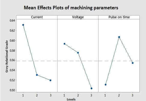
Table 6: Results obtained from machining Inconel 718 using copper electrode in Die sinking EDM
Ex p No Cur rent (A) Gap Voltag e(V) Pulse on time( μsec) MRR (mm3/mi n)
Ra (μm)
TWR (mm3/min)
1 2.5 80 80 0.0946 1.7
1 0.00236
2 2.5 120 100 0.0147 0.9
2 0.00232
3 2.5 160 120 0.0604 1.6
2 0.00279
4 3 80 100 0.04 0.8
2 0.00725
5 3 120 120 0.148 1.7
6 0.0044
6 3 160 80 0.1263 1.8
3 0.00607
7 3.5 80 120 0.24 1.8
9 0.0092
8 3.5 120 80 0.202 1.9
2 0.0106
9 3.5 160 100 0.206 1.8
9 0.00976
IV. RESULTS AND DISCUSSION
The machining of inconel 718 with copper electrode
considered was analyzed and from the parameters selected the electrode was found safe. But it is required also to get optimum parameter to achieve low surface roughness, good MRR and low TWR. Taguchi based Grey Relational Analysis was used to find the optimum parameters. Also the contribution of each parameter, developing a mathematical model to connect input and output parameters were also carried out.
Fig.14: Effect of peak current (Ip) and pulse on time (Ton) on MRR
4.1 Material Removal Rate
In fig 14 MRR increases when peak current and pulse on time increases. When Ton= 100 and 120,the MRR value reduced. This is comparable to [18] ,where pulse on time greater that 100us , inversely affect the material removal rate Reduction in MRR might be due to the effect of expansion of plasma channel which is more than the effect of the increase in sparking time. Due to expansion of plasma channel, the energy density of discharging spots decreases which is not enough to melt work material and hence rate of material is lowered down.
0 0.05 0.1 0.15 0.2 0.25 0.3
80 100 120
M R R ( m m 3/m in )
Pulse on time (Ton) µsec
Material Removal Rate (MRR)
Infogain Publication (Infogainpublication.com) ISSN : 2454-1311
Fig.15: Effect of peak current (Ip) and pulse on time (Ton) on TWR
4.2 Tool Wear Rate
The fig 15 shows the effect of peak current and pulse on time on TWR. As Ip increases, higher spark energy is produced, which results in higher MRR and TWR. As Ton increases, a decrease in TWR is observed except for a few readings. The decrease is due to fact that, when Ton increase it leads to spreading of the spark (plasma channel) thereby reducing the heat transfer to the tool[19]. This lead to the deposition of carbon on electrode thereby reducing TWR. 4.3 Surface Roughness
Fig.16: Effect of peak current (Ip) and pulse on time (Ton)
with Ra
Fig 16 shows the effect of peak current and pulse on time on surface roughness (Ra). Ra decreases with decrease in peak current due to shallow and flat crater formation. When peak current increases, the discharge energy increases and result in more MRR and producing large, deeper crater which increase the surface roughness. The lowest surface roughness value is found at Ton = 100 and current = 3A. At this stage the TWR is found to be higher and MRR lower.
V. OPTIMIZATION OF MACHINING PARAMETERS
5.1 Calculation of Normalized values
To avoid the effect of adopting different units and reduce the variability, the response data is pre-processed[5]. The
experimental results are normalized in the range between zero and one. The normalization can be done in three different approaches;.
For larger the better
x∗ k = (1)
For smaller the better
x∗ k = (2)
For nominal the better
x∗ k = 1 − (3)
5.2 Finding Grey Relational Coefficient (GRC)
Following data pre-processing, a grey relational coefficient (GRC or φ) is calculated to express the relationship between the ideal and actual normalized experimental results. The grey relational coefficient can be expressed as;
φ k = ∆ δ∆
∆ δ∆ (4)
Where, δ is the weightage coefficient usually taken 0.5 and
∆ represents the deviation and is given as follows;
∆ k = |x∗ k − x∗ k | (5)
∆ = max|x∗ k − x∗ k | (6)
∆ = min|x∗ k − x∗ k | (7)
5.3 Finding Grey Relational Grade
The grey relational grade is obtained by taking the average of greyrelationalcoefficients.
γ =#∑ %#φ k (8)
Where, γi = Grey Relational Grade n= number of response factors
Ranks are provided according to the decreasing order of grey grades for all experiments as shown in Table 7. First rank corresponds to highest value of grey grade among 9 values.
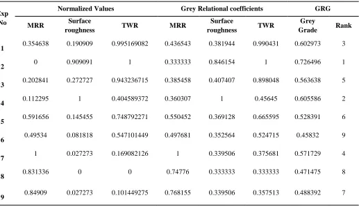
Fig.17: Mean effect plot for grey relational grade
0 0.002 0.004 0.006 0.008 0.01 0.012
80 100 120
T
WR
(
m
m
3/m
in
)
Pulse on time (Ton) µsec
Tool Wear Rate (TWR)
Ip = 2.5 A Ip = 3 A Ip= 3.5 A
0 0.5 1 1.5 2 2.5
80 100 120
R
a
(
µ
m
)
Pulse on time (Ton) µsec
Surface Roughness (Ra)
Infogain Publication (Infogainpublication.com) ISSN : 2454-1311 Table 7: Grey Relational Grade (GRG)
Exp No
Normalized Values Grey Relational coefficients GRG MRR Surface
roughness TWR MRR
Surface
roughness TWR
Grey
Grade Rank
1 0.354638 0.190909 0.995169082 0.436543 0.381944 0.990431 0.602973 3
2 0 0.909091 1 0.333333 0.846154 1 0.726496 1
3 0.202841 0.272727 0.943236715 0.385458 0.407407 0.898048 0.563638 5
4 0.112295 1 0.404589372 0.360307 1 0.45645 0.605586 2
5 0.591656 0.145455 0.748792271 0.550452 0.369128 0.665595 0.528391 6
6 0.49534 0.081818 0.547101449 0.497681 0.352564 0.524715 0.45832 9
7 1 0.027273 0.169082126 1 0.339506 0.375681 0.571729 4
8 0.831336 0 0 0.74776 0.333333 0.333333 0.471475 8
9 0.84909 0.027273 0.101449275 0.768155 0.339506 0.357513 0.488392 7
Table 8: Response table for grey relational grade
PROCESS PARAMETERS
Grey Relational Grade
Level 1 Level 2 Level 3
Max-Min Rank
CURRENT 0.631035* 0.530766 0.510532 0.120503 1 GAP
VOLTAGE 0.593429* 0.575454 0.50345 0.089979 3 PULSE ON
TIME 0.510923 0.606824* 0.554586 0.095902 2 Total mean of Grey grade = 0.557444
* Optimum Levels
5.4 Analysis of Variance (ANOVA).
The aim of analysis of variance (ANOVA) is to investigate which of the tool parameters significantly affect the performance characteristics. ANOVA test establishes the relative significance of the individual factors and their interaction effects
Table 9: Results of ANOVA
SOURCE DF SS MS F %CONTRIBUTION CURRENT 2 0.024984 0.012492 6.903911 44.58341 VOLTAGE 2 0.013604 0.006802 3.75918 24.27567
PULSE
ON TIME 2 0.013832 0.006916 3.822289 24.68321 ERROR 2 0.003619 0.001809 1 6.457704 TOTAL 8 0.05604 0.007005 15.48538 100
Table 9 shows peak current is the most contributing factor in machining of Inconel 718 using copper electrode in die sinking EDM.
5.5 Mathematical model for prediction of optimal machining parameter
The regression equation for the prediction of optimal machining parameter is obtained from MINITAB software. The regression equations obtained are as follows;
Regression equation for MRR = -0.383+ (0.1594 x I)+(0.000075 x V) +( 0.00021 x Ton)
Regression equation for Ra = -0.16 + (0.483 x I) +( 0.00383 x V) – (0.00158 x Ton)
Regression equation for TWR = - 0.01371+ (0.007363 x I) – (0.000001 x V) – (0.000022 x Ton)
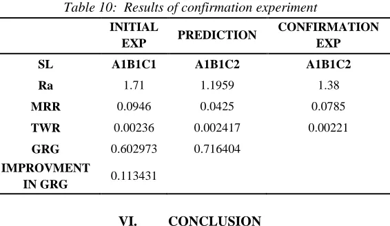
5.6 Confirmation experiments
The results obtained from the mathematical model is verified followed by calculation of optimum grey relational grade and improvement in grey relational grade is carried out.
Optimum grey relational grade
Infogain Publication (Infogainpublication.com) ISSN : 2454-1311 Table 10: Results of confirmation experiment
INITIAL
EXP PREDICTION
CONFIRMATION EXP
SL A1B1C1 A1B1C2 A1B1C2
Ra 1.71 1.1959 1.38
MRR 0.0946 0.0425 0.0785
TWR 0.00236 0.002417 0.00221
GRG 0.602973 0.716404
IMPROVMENT
IN GRG 0.113431
VI. CONCLUSION
The modeling of electrode clusters to develop the LPOT turbine rotor is generated with the help of NX software. By the development of these electrode clusters, the time and effort is significantly reduced, as all the blades are machined at the same time. In the process of generation of electrode, one of the electrode is found to have an attenuate or thin section/ portion. The safety of the electrode and required finish was the main concerns, for that the attenuate section alone was considered for parametric study. Different input parameters and responses were chosen and experimental design by L9 orthogonal array was used. The experiment was carried out in 4 axis CNC EDM machine and the results were tabulated. The requirement was to obtain good surface finish, low TWR and good MRR, so the parameter optimization using Grey Relational Analysis was performed.
From the GRA the optimum parameters were found as; Current 2.5 A (Level 1), Gap voltage 80 V (Level 1) and Pulse on time 100 μsec (Level 2). The area of the considered electrode is 50mm2; the current density corresponding to optimum current is 5 A/cm2and can be related to the actual job, where the area is more compared to the electrode in the study. From the experimental study the thin section was safe and the optimum parameters aid in achieving low TWR, good surface finish and MRR. From ANOVA test, the current has significant effect on the MRR, TWR and Ra and it contributes 40.51764 %, Pulse on time 24.6832 % and for voltage 24.27567 %. By comparing the initial and the confirmation experiment, improvement in surface finish about 19.29%, reduction in MRR of 17.01 % and reduction in TWR of 6.35% was observed.
REFERENCES
[1] Pushpendra S. Bharti, S. Maheshwari & C. Sharma, “Experimental Investigation of Inconel 718 during die sinking Electric Discharge Machining”, Int. J of Engineering Science and Technology Vol 2(11) 2010, 6464-6473
[2] N. Pragadish , M. Pradeep Kumar “Optimization of Dry EDM Process Parameters Using Grey Relational
Analysis” Research Article - Mechanical Engineering Arabian Journal for Science and Engineering pp 1-8. [3] Dr. Rajeev kumar garg, Kuldeep ojha “A review of
tool electrode designs for sinking EDM process ” Recent Researches in Multimedia Systems, Signal Processing, Robotics, Control and Manufacturing Technology ISBN: 978-960-474-283-7
[4] P.Narender Singh, K. Raghukandana, B.C. Pai “Optimization by Grey relational analysis of EDM parameters on machining Al–10%SiCP composites ” Journal of Materials Processing Technology Volumes 155–156, 30 November 2004, Pages 1658–166 [5] N. Radhika, G. Chandran, K., Shivaram, P., and
Karthik, K. T. Vijay “ Multi-objective optimization of edm parameters using grey relation analysis” Journal of Engineering Science and Technology Vol. 10, No. 1 (2015) 1 - 11
[6] Włodzimierz, Jacek Tota, “Modern technology of the turbine blades removal machining” The Institute of Advanced Manufacturing Technology, 30-011 Cracow, ul. Wroclawska 37a, Poland 2007
[7] Kanthasamy M., Remesh G , Dr. Narayanan V , Thomas Raju.P , Kartha N R Vishnu "Experimental studies for semi-cryo engine development” Indian Journal of CryogenicsYear : 2014, Volume : 39, Issue : 1 pp: 106-116.
[8] X. M. Ding, J. Y. H. Fuh, K. S. Lee “Computer aided EDM electrode design” computers & industrial engineering 42(s 2–4):259–269 · april 2002. [9] M. Rahman, W.K.H. Seah and T.T. Teo “The Machinability ofIncone1 718” Journal of Materials Processing Teclmology 63 (1997) 199·204
[9] M. Rahman, W.K.H. Seah and T.T. Teo “The Machinability ofIncone1 718” Journal of Materials Processing Teleology 63 (1997) 199·204
[10] G. Rajyalakshmi, P. Venkata Ramaiah “Multiple process parameter optimization of wire electrical discharge machining on Inconel 825 using Taguchi grey relational analysis” The International Journal of Advanced Manufacturing Technology November 2013, Volume 69, Issue 5, pp 1249–1262.
[11] David K. W. Ng “Grey System and Grey Relational Model ” ACM SIGICE Bulletin Volume 20, Number 2, October 1994.
[12] Lohithaksha M Maiyar, Dr.R.Ramanujam , K.Venkatesan , Dr.J.Jerald “Optimization of Machining Parameters for End Milling of Inconel 718 Super Alloy Using Taguchi Based Grey Relational Analysis” International Conference on design and manufacturing, IConDM 2013 , Procedia Engineering 64 ( 2013 ) 1276 – 1282.
Infogain Publication (Infogainpublication.com) ISSN : 2454-1311 superalloy” The International Journal of Advanced
Manufacturing Technology May 2013, Volume 66, Issue 5, pp 1015–1023.
[14] Somnath M. Kale, D.S.Khedekar “Optimization of Process Parameters in Electric Discharge Machining Of Inconel 718 by Using Copper Electrode” OSR Journal of Mechanical and Civil Engineering (IOSR-JMCE), Volume 13, Issue 3 Ver. III (May- Jun. 2016), PP 51-55.
[15] Mao-yong LIN, Chung-chen TSAO, Chun-yao HSU, Ai-huei CHIOU, Peng-cheng HUANG, Yu-cheng LIN “Optimization of micro milling electrical discharge machining of Inconel 718 by Grey-Taguchi method” Transactions of Nonferrous Metals Society of ChinaVolume 23, Issue 3, March 2013, Pages 661-666 [16] E.O. Ezugwu (2005) “Key improvements in the
machining of difficult-to-cut aerospace superalloys” [17] Rajesha S., Sharma A., and Kumar P. (2011)” On
Electro Discharge Machining of Inconel 718 with Hollow Tool” Journal of Materials Engineering and Performance. 1-10.
[18] Paramjit Singh, Anil Kumar, Naveen Beri & Vijay Kumar, “Influence of Electrical Parameters in Powder Mixed Electric Discharge Machining(PMEDM) of Hastelloy”, J of Engineering Research and Studies (Oct-Dec 2010) 93-105