* To whom all correspondence should be addressed. E-mail: eskrni@gmail.com
Leakage Analysis of Metal Progressive Cavity Pump
Ramasamy Karthikeshwaran
Department of Petroleum Engineering, AMET University, Chennai - 603 112, India. doi: http://dx.doi.org/10.13005/bbra/1431
(Received: 15 August 2014; accepted: 10 October 2014)
A Progressive cavity pump is an artificial lifting technique used in oil and gas industries to pump heavy and sandy fluids from the low bottom hole pressure wells. The pump is a positive displacement pump having rotor and stator as the main component of the pump. The performance of pump gets decreased as the clearance between the rotor and stator increases. Increasing fluid viscosity has positive effect on the performance. The performance degradation of the pumpoccurs due to leakage flow through the least clearance gap between the rotor and stator. A computational work has been performed to find the characteristics of the leakage flow and Ansys CFX 12.1 software was used for the simulations. Meshing and solving of the fluid dynamics equation were done by Ansys CFX mesh and CFX solver, respectively. Present article presents the prediction of leakage for different fluid viscosities and diametric clearances.It was found that the rotor rotation helps in leakage flow if the flow and rotor surface velocity directions are same.
Key words: Artificial lift, Leakage, progressive cavity pump, interference fit.
An artificial lift (AL) is the technique used to lift the hydrocarbons when there is a pressure decline in the wellbore by mechanical means.The ALsprovide additional energy to increase the pressure through rotating or reciprocating action of the mechanical equipment or injecting fluid into the well. There are several AL techniques such as sucker rod pump, electric submersible pump, gas lift etc and those are incapable of handling fluid having high viscosity and solid particle mix. Progressive cavity pump (PCP) is one of the AL techniques used to handle the complex conditions of heavy and sandy fluids.In 1930, Rene Moineau proposed the idea of PCP which is now being used in oil and gas industry as a down-hole pump and
mud motors1. PCP works with the principle of
Archimedean screw mechanism. PCP is a positive displacement pump and performance depends on several factors including diametric clearance between rotor and stator and fluid viscosity.
length of stator. Hence five-stage PCP will have five pitch lengths of stator and ten pitch lengths of rotor. To employ PCP successfully in any well, it is necessary to know the fluid property and well condition. Higher clearance can be all right for higher viscosity fluid while thin fluid may require a negative clearance.
A very limited number of efforts have been applied to capture flow physics by the laboratory experiment and recently some computational efforts have been tried3-6. The experimental results made
an evolution of PCP design and these were infeasible because the experimental setups were unable to simulate the extreme well conditions. The computational approach to model the flow within the pumps has been started in the last decade to predict the PCP performance. The evolution of theoretical methods related to flow simulation started with the simplest two and three dimensional modeling. A method to model the flow within PCP stator and rotor were presented byBelcher2. The
flow within stator and rotor is termed as ‘capsulism’ by Rene Moineau in 19301. He modeled the flow
considering infinite parallel plate model to approximate the leakage flow within PCP through convergent-divergent bearing. The hydraulic behavior of PCP in two and three dimensional cases with symmetric and non-symmetric geometry was presented by Gamboa et al.3. They simulated three
models such as infinite parallel plate,untwisted model or developed model and fully developed model.They assumed thatthe fluid was strictly laminar, Newtonian, single phase and incompressible and they considered constant temperature. Gamboaet al.4 reported that the slip
flow had two components: one was due to the position of rotor and the other one was due to the differential pressure between the cavities. Another approach5 was to establish the relationship
between differential pressure and flow rate.The above literatures were to find the flow behavior of fluid within the PCP.Paladinoand DeLima6 tried
moving mesh strategy to model the CFD system but they validatedtheir results only for limited ranges.
In the present approach, a simple PCP geometry has been generated to capture the flow physics during rotor rotation. A computational fluid dynamics method has been used for three dimensionalsimulations.
Progressive cavity pump leakage flow
PCP consists of rotor and metallic or non-metallic stator. The non-non-metallic stator makes ideally zero clearance or leakage while the metallic stator needs clearance due to mechanical reasons and produces higher amount of leakage. In present work, metallic stator case was considered. The fluid flows between stator and rotor clearance gap with differential pressure of ΔP at a rotor speed of Nis called leakage flow. The fluid in the cavity tends to move progressively along the length of the pump and generates head. In PCP, the theoretical flow rate is based on geometry and rotational velocity of the rotor. The geometric parameters which play a role in the flow rate are eccentricity (e), length (Lp) of the pump and rotor minor diameter (dm). Hence the theoretical flow rate Qth is defined as7:
Qth=S*N ...(1)
S = 4edmLp ...(2)
The actual flow rate is much less than the theoretical flow rate because of leakage. Gamboa
et al.3 presented an experimental result in metal
PCP for the fluid of different viscosities of 1cP, 42cP, 481cP flowing in a clearance of 0.185mm at different speeds. Gamboa et al.,4 and Pessoa et
al.,5 reported the computational result for of metallic
statorPCP considering same parameters which are taken for experimental work3. The results of
experimental and computational workfor water at a speed of 300rpmare plotted for a PCP having a positive clearance of 0.185mm (Fig. 1). The theoretical flow rate of elastomeric stator PCP which has zero clearance shows a horizontal line in the figure.Gamboa et al.,4 did not specify the
friction factor for material used in experimental setup but Pessoa et al.5 considered the different
friction factor to present a result and validated the results. The experimental and computational results show that the flow rate decreases as the differential pressure (ΔP) increases.
The fluid flow in PCP occurs because of rotor motion. Because of different pitch length, the rotor meets the stator and forms a cavity and the cavity moves during rotor rotation (Fig. 2). If the cavity is filled with liquid, the liquid gets transferred from inlet to outlet and generated head. Gamboa et al.4 approximated the slip in
the Hagen Poiseuille equation and the platesare shown in Fig. 3. The leakagecan be calculated from the formula:
(3)
whereS, C, ”P andµ are the leakage, generic constant, differential pressure and dynamic viscosity, respectively. Width, breadth and length of the parallel plates are represented as w, b and L
respectively.From this equation it can be concluded that increasing viscosity and leakage length, the leakage will be reduced while increasing the pressure difference will increase the leakage.
Finite volume method of analyzing the fluid flow between the stator and rotor is quite complicated, when the rotor is in translation and rotational motion with or without mesh deformation. The mesh deformation is an important component for solving problems with moving boundaries or moving sub-domains6. Present problem was
simplified by taking a unit length instead of one pitch of stator. The length of the leakage line was calculated and leakage flow for a pitch or a stage has been calculated. The problem was defined by flow between parallel plates with rotating rotor (Fig. 4). In the figure, it can be seen that the rotor is inside a stator. The length of the stator is w. The leakage area is at the top and bottom of the rotor in the figure. The inlet pressure was kept higher than
the outlet pressure so that a leakage flow can be maintained. The rotor was given a rotational speed of 300rpm. Translation motion of the rotor was not considered in the present computation to make the problem simpler.
The cavity inside the PCP is very complex in terms of CFD analysis and a mesh deformation is required. The authors has tried but failed due to thinsection meshing problem. Further resolving the zonal meshing may solve the deforming or moving mesh related issues. Here one point can be noted that the rotor and stator is not twisted. The system has made straight so that an untwisted and parallel plate rotor model can be resembled [2].
Geometryand computational approach
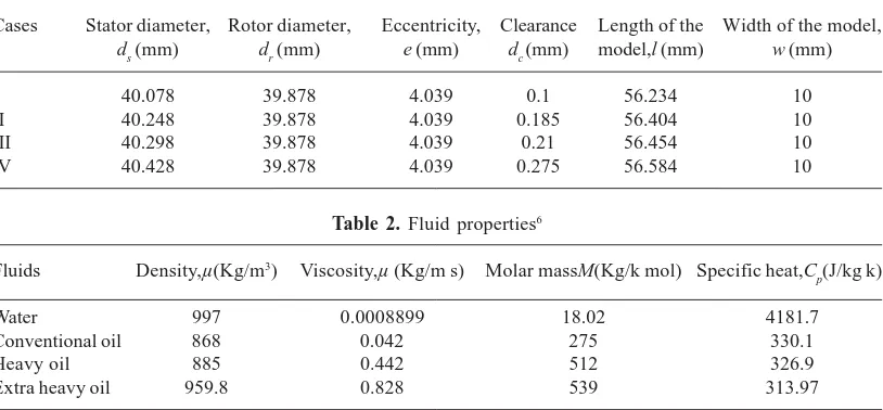
Geometryfor the computation is shown in Fig 4. Several geometrieshaving clearance values 0.275, 0.21, 0.185 and 0.1mm were generated (table 1)by a CAD software. Based on the diametric clearance, length, breadth and stator diameter (ds)was varied and length (l) of the model was calculated from the formula:
l = ds+4e (4)
where, e is the eccentricity.
Four different fluids were used to analyze the leakage (Table 2). The density, viscosity, molar mass and specific heat capacity were the fluid properties which were taken as major parameters in the analysis. First three properties decide the
Table 2. Fluid properties6
Fluids Density,µ(Kg/m3) Viscosity,µ (Kg/m s) Molar massM(Kg/k mol) Specific heat,C
p(J/kg k)
Water 997 0.0008899 18.02 4181.7
Conventional oil 868 0.042 275 330.1
Heavy oil 885 0.442 512 326.9
Extra heavy oil 959.8 0.828 539 313.97
Table 1. Different geometries of parallel plate model
Cases Stator diameter, Rotor diameter, Eccentricity, Clearance Length of the Width of the model, ds (mm) dr (mm) e (mm) dc (mm) model,l (mm) w (mm)
I 40.078 39.878 4.039 0.1 56.234 10
II 40.248 39.878 4.039 0.185 56.404 10
III 40.298 39.878 4.039 0.21 56.454 10
ease of flow within the domain and the last one decides the heat transfer characteristics within the domain.
The computations were performed for the speed of 300rpm and the reference pressure and temperature were considered 1atm and 25°C, respectively. Isothermal heat transfer model along with K-epsilon turbulence model was used. The flow direction was normal to the inlet boundaryand 5% turbulence intensity was employed at the inlet.The Outlet pressure was set to 20, 30, 40 and 50psi for the different cases.
An unstructured tetrahedral grid system was used to solve the leakage flow. For the convergence criteria, residual value of root mean square (RMS) for all flow parameters was set to 0.0001. The solver finished the simulation basedon the properties of fluid and the maximum number of iterationsequaled to 600 was observed for a most complicated case such as less viscous and very narrow leakage path. Grid independency test for the parallel plate model of stator and rotor was performed(Fig. 5). Among different number of mesh nodes, approximately 8000 nodes were selected as an optimum number of nodes.
The present work reportssimulations of severalgeometries and fluids. The convergence runs of the simulations were different for different simulations.Time scale, root mean square value and the number of iterations were changed based on the geometry and fluid property to get a better converged solution. The mass and momentum residuals are shown in Fig.6. The convergence was achieved at a time span of 1.5 hours for single analysis in a host computer of Intel core 2 Duo processor of 2.93GHz speed and 3GB RAM.
RESULT AND DISCUSSION
Initially several geometries having different clearance gap were generated and those were meshed in Ansys mesh. The mesh was checked for its grid independency (Fig. 5) and 8000nodes were selected as an optimum number of nodes. The next step was to validate the result with previous works. There are not enough articles on numerical work as the metallic stator PCP was recently developed. The elastomeric and metallic stator PCP differs because the elastomer gets deformed by the rotor rotation and fluid pressure.
Hence the elastomeric data cannot be used to validate the CFD result which is done for metallic stator only. In the case of elastomeric stator, it is assumed that a zero clearance will be maintained all time and there will be no leakage flow. In practice, elastomeric PCP has leakage and as a thumb rule, 75psi head per stage gets generated in the oil filed PCPs. Increasing leakage flow, head gets decreased.If pressure ratio is increased across the PCP, the leakage flow increases and head or flow rate per stage gets decreased (eqs. 1-3).
Figure 7 shows that the present result matches well with the previous works. The computations were performed up to 15 psi pressure difference and leakage flow rates were compared. The experimental results of Gamboa et al [3] show that the leakage increases with the increase in pressure difference. The computational result [5] over estimated the leakage flow. In the present computation also over estimates but it ismuch less than the previous numerical work [5]. The computational and experimental results were based on 0.185mm clearance and 300rpm speed.
The present computations were faced challenges in terms of meshing and convergence. The effort to apply deforming mesh was failed and a simpler method of rotation of the rotor was applied. The thin section of clearance zone was facing problem and a local meshing was applied. The convergence in the case of the thin section produced some failed results. It is expected to get better result if the thin section meshing issue is resolved and a moving mesh or immersed boundary method is applied.
Figure 8 shows the variation of leakage flow rate for different viscosities and clearances. The rotor speed was maintained at 300rpm and differential pressure was varied from 10 to 40 psi. The trend shows that the leakage flow rate increases with the increasing in differential pressure across the clearance. On the other hand, leakage flow rate decreases as pressure varied from 10 to 40 psi. The leakage flow rate increases with the increasingin differential pressure across the clearance. On the other hand, leakage flow rate decreases as the viscosity increases. The viscosity is defined as ‘resistance to flow’, hence the figure shows that the reduction in flow rate because of flow resistance due to higher viscosity.
flow rate because the fluid gets larger space to flow. Figure 9 shows the variation in leakage flow rate with respect to clearance and the leakage flow rate. The analysis is done for the viscosities 42cP, 421cP and 828cP of fluid at a speed of 300rpm. Figures for the differential pressures 10 and 40psi are shown. These plots explain the ease of fluid flowing in the clearance. Leakage flow rate increases as the viscosity decreases. Increasing the clearance the fluid leakage increases but at the same time viscosity controls the leakage flow. Both figures show that increase in leakage flow rate due to increase in differential pressure. This conclusion is supported by eq. 3 where it showsS “ ”P.
Figure 10 shows the leakage flow rate of different viscosity fluid flowing in the clearances of 0.275, 0.21, 0.185 and 0.1mm and this shows the variation of leakage flow rate for different clearance of the parallel plate model when there is a change in differential pressure. The trend followed in these plots is same for all fluid viscosities; i.e., the leakage increases as differential pressure increases as this can be concluded from the Equation 3. The leakage flow rate increase as the clearance increases.
Figure 11 shows the velocity profile of the leakage area. The plane has been taken at the mid section of the clearance gap (Fig. 4). The top surface implies that the rotor surface velocity due to rotation helps the leakage flow while that of the bottom surface opposes the leakage flow through the leakage gap. Hence the top surface shows higher velocity through the gap than that of the bottom surface. Increasing the clearance the flow velocity also increases because the fluid gets wider path to flow.
CONCLUSIONS
A computational analysis of progressive cavity pump leakage flow has been performed using a commercial programming code. From the computation work, the conclusions were made by varying geometric clearance, viscosity, differential pressure etc. It was found that the leakage flow
increases by increasing clearance and differential pressure across the clearance gap. The metal PCP is notoriousbecause of less efficiency due to the large clearance. The leakage flow reduces as the viscosity increases. Hence PCP is most suitable for thick fluid pumping and metal PCP can work in this case. Several stages of PCP are required for high differential pressure and metallic stator PCP will require much larger number of stages than the elastomeric stator PCP. The rotor surface velocity helps or opposes the leakage flow according to the rotational direction of the rotor.
REFERENCES
1. Moineau, R., 1930, “A New Capsulism,” Doctoral Thesis, The University of Paris, France.
2. Belcher, I., 1991, “An Investigation into the Operation Characteristic of Progressive Cavity Pump,” Doctoral Thesis, Cranfield Institute of Technology, United Kingdom.
3. Gamboa, J., Olivet, A., Iglesias, J. and Gonzalez, P., 2002, “Understanding the Performance of a Progressive Cavity Pump with a Metallic Stator,” Petroleos de Venezula, S.A (PDVSA), Los Teques, Venezula.
4. Gamboa, J, Olivet, A, and Espin, S., 2003, “New Approach for Modelling Progressing-Cavity-Pump Performance,” SPE Annual Technical Conference and Exhibition, Coloroda, USA. 5. Pessoa, P.A.S., Paladino, E.E. and DeLima, J.E.,
2009, “A Simplified Model for the Flow in a Progressive Cavity Pump,” 20th International Congress of Mechanical Engineering, Gramado, Brazil.
6. Paladino, E. E. and DeLima, J. A., 2009, “Computational Three Dimensional Simulation of the Flow Within Progressing Cavity Pumps” 20th International Congress of Mechanical Engineering, Gramado, RS, Brazil.
7. Ahmed, T., 2000, “Reservoir Engineering Handbook Second Edition,” Gulf Publishing Company, Houston, Texas.