Fault Detection probability evaluation approach in combinational circuits
using test set generation method
Namita Arya1, Amit Prakash Singh2
University of Information and Communication Technology, Guru Gobind Singh Indraprastha University Dwarka, New Delhi, India
1[email protected], 2[email protected]
Abstract:This paper introduces an approach that chooses the fault detection by calculating probabilities using probability mass function (pmf) and cumulative distribution function (CDF). This work used a method for multiple stuck-at faults by producing a new test pattern in combinational circuits. We assumed that existence of all multiple faults is only because of one single component that is faulty. A complete test set can be created by all possible single stuck-at faults in a combinational circuit using some combination of gates. The test set generation fault detection method is applied on two different 3-bit input variable and 4-bit input variable circuits. The probability of error occurrence is calculated at both 3-bit and 4-bit input variable circuits. The resulting feature is used to obtain maximum error occurrence probability to detect faults by the logic used that the complexity of the circuit is inversely proportional to the fault occurrence probability. Then again, undetectability is directly proportional to the complexity of the circuit. Therefore, finest feasible circuit should have large input variable components with less complexity to reduce the fault occurrence probability.
Keywords: Combinational Circuits, Fault Detection, Test vector generation, Error occurrence Probability estimation, Probability mass function, and cumulative distribution function.
1 Introduction
A digital circuit may not meet its guarantees if the circuit experiences transient and permanent faults. There is no fixed approach to detect intermittent faults [1], although they may fix during repletion of operations. Then again, the open and short permanent faults may change the logical behaviour of the circuit.The test procedure for a digital circuit is a common research area for circuit implementation. It is evident that only a limited number of faults such as short circuit faults, open circuit faults and stuck- at faults are present in the digital circuits [2]. Stuck-at fault model has been broadly utilized as a part of the industry. In this model it is assumed that the fault causes a line in the circuit to behave as if it is permanently at logic 0 or logic 1. If the line is permanently at logic 0 it is said to be 2 stuck-at 0 (s-a-O), otherwise if it is permanently at logic 1 it is called to be stuck-at 1 (s-a-1) [3].
Therefore the logic circuit is said to be faulty with stuck-at fault one (stuck-at-1) and stuck-at fault, zero (stuck-at-0) respectively if the signals are permanently high [4, 5]. Though, single stuck-at fault, may be present in the circuit for more than one at a time. These faults may be the cause of variation in the output of the circuit. The circuit output value may be different from a set of input combinations that are called test set for the circuit. Such input combinations may give an incorrect value in the output, which the
results can be called test for that circuit. All the input combinations being tested for a specific fault constitute the complete test set for that fault. This type of the combinational test set vector is called complete test set for the testing of the whole system [6-8]. There must be at least one test for each detectable fault in complete fault test combinations. These numbers of the test results must be less than or equal to the number of all possible combinations of the input present in the circuit. The complexity of the system is directly proportional to the ability of fault detection of test set generation approach [9]. A very big number of fault detection models already have been projected in digital logic circuits [10, 11]. Single stuck-at model is the most common model for fault detection. It is assumed that at least one fault is present in the circuit at any given time period with the test set generation method in fault detection. A test set pattern, which can detect all possible single stuck-at faults can also detect many faults present in any other test models [12, 13].
A novel approach is offered to abstain from layout faults for the digital circuit without the exercise of any fault model which are founded on a fault detection pre-analysis of the circuit. Instead, this work is based on resynthesis of sub circuit and this raw approach to determine the single stuck at fault [14].
While following this new approach, it is important to activate the correct measure of time while testing the circuits using random or pseudo-random patterns that are called test length. These include an exact expression and an approximation for the expected fault coverage. The influence of each fault on the expected fault coverage can then be measured. Relationships between test confidence, fault coverage, fault detectability, and test length are also examined.
Techniques for designing fault tolerant combinational circuits were proposed using functional blocks of a VLSI-system to increase the reliability R (t) by means of linear error correcting codes (ECC). This novel technique is based on concurrent error detection and correction approach which is called CLC (coded logical channels). This technique can be extended to multi-output circuits and compares it with the Triple Modular Redundancy (TMR) technique [15]. Redundancy is the ground work of functional efficacy that would be spared to make fault-free environment. This functional approach consists some backup components that automatically replace faulty components at the time of any fault occurrence thus it prevents the whole circuit failure [16]. This redundancy technique is the best approach to enhance circuit reliability for the combinational digital circuit. Software reliability approach was proposed to detect errors on the basis of error occurrence probability for different test sets [17].A large number of probability evaluations create large estimation approaches. To address this issue an incremental delay fault detection probability computation algorithm is monitored which is convenient for the inner loop of automatic test pattern generation approach [18, 19]. Two algorithms, the complete coding algorithm, and the gate blocking algorithm was proposed to address the issue of bounding fault detection probabilities in combinational circuits. Both algorithms rapidly create test sets for specific faults [20, 21].
applications. A scheme that consists of many components is more authentic than any other system [25]. If a system runs in maximum time intervals without any failure, it is called fault tolerance system. Fault tolerance system capability is measured by mean time between failures (MTBF) run because of its distinct components. This mean time between failures is a probability measure of failures. It is calculated in the maximum interval of run time.
The simple chain rule applied by which incomparably reduces the computation of the detection probabilities for single stuck-at faults at the particularized signal lines of the circuit [26] adapted conventional algorithms for generating reduced test sets into n-detection algorithms.
In this paper, we are estimating maximum error occurrence probability, by probability mass function by comparing different test set input circuits.
A logic called ft-Maj has been proposed for a fault tolerant architecture in QCA. It is based on hybrid cell orientation [27] .The fault tolerance architecture has been examined in undeposited cell defects and 97.43% fault tolerance has been achieved. With this application only two test vectors {001, 011} can give 100% fault tolerance.
Design methodologies of reversible fault tolerant unidirectional, bidirectional and universal barrel shifters have been proposed having the capability of detecting errors at its primary outputs [28]. A fault model creation is important for fault diagnosis. A novel fault-tolerant control system for a class of nonlinear systems has been designed for fault detection and diagnosis (FDD) with multiple model methods [29]. We are assuming a fault model to test the different outputs for different inputs to justify our statement. The objective of this paper is to justify the statement that more redundant circuit can be more reliable circuit by error occurrence probability estimation. As we know that different combinations of the circuits can change error rates. This paper monitors the error rates in different combinations of components by simulating in the Proteus software [30]. This paper justifies the maximum error rate by probability mass function analysis.
The rest of this paper is catalogued under the following sections. Review of existing fault independent testing algorithms and fault probabilities are presented in section 1. Section 2 provides a detailed description of the test set generation method. Section 3 defines the use of detectability and undetectability concepts in different circuits. Experimental results, when the proposed algorithm is applied for estimation of fault occurrence in different input variable circuits are detailed in Sec. 4. Finally, conclusions are summarized in section 7.
2. Research Methodology
The complexity of the system is directly proportional to the ability of fault detection of test set generation approach. We focus on this statement in this work and justify the statement using the self test set generation method by comparing circuits with different inputs. The bridging fault is a type of fault where two input signals get connected which should not be connected. The dominating input either 1 or 0 dominates into the circuit to have the result by its dominating property according to itself. It has been stated that all single stuck-at faults can be detected only by different sets of inputs. This assumption is called self-testing property. We use this concept of fault bridging in reference model.
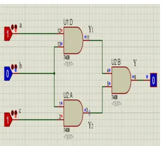
A test set T detects the fault t if Yf (T) ≠ Y (T), the faulty output is not equal to fault free output. Let us assume a test set (011) for the circuit shown in fig1.
fig.1 Assumed circuit standard for a test set 011.
= . = ( + ) (1)
= . = ( + ) (2)
(011) = = (0.1)(1.1) = (0.1) = 0 (3)
(011) = . = (0 + 1). (1). (0 + 1) = 1.1.1 = 1 (4)
Here and are complementary of each other. By complementary logic function: ( ) ⊕ ( ) = 1 (5)
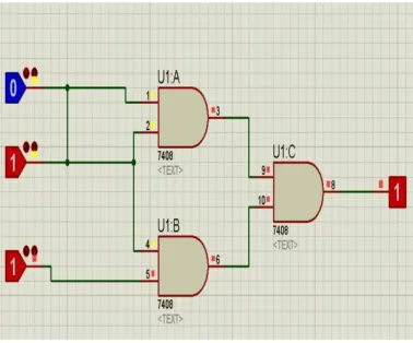
A set of inputs which detect all possible errors is called a complete detection test set. Any of the possible input differentiate one fault from another fault if Ya≠ Yb or Ya ⊕ Yb= 1.. Any set of tests which distinguish all pairs of fault is called a complete location test set. Test set provides specific output of the circuit. If any of the input gets stuck at any logic the circuit may be faulty at the output. In order to provide a test set for the circuit, we can detect and distinguish faults by different stuck-at faulty inputs. We adopt a new test set (101) for the circuit as shown in fig2a. Let us consider that the stuck at-fault present at the input (b=1). Stuck at fault at the input (c=0). By considering the stuck at-faults at the inputs the outputs are determined: = ( = 1) = ( = 0) (6)
= . , = . . . = . + . = . + . = ( + ) (7)
(101)
= 1. (1 + 1) = 1
= 0. (1 + 1) = 0
fig 2a Assumed circuit standard for a complete test set 101.
It is specified that and are complementary to each other as fig 2b.
fig 2b Complementary circuit of fig1 and fig2a.
⊕ = 1 (8)
Thus, this test set (101) distinguishes two faults present in the circuit as and .
3. Fault detection probability estimation
3.1 Detectability
given circuit. Detectability is a unit to define whether a fault can be detected or not. Detectability is a ratio of a number of faults to the number of inputs. If this ratio is greater than or equal to 1 that means faults present in the circuits are detectable.
= ≤ 1 (9)
Eq. (9) is the detectability formula which shows that faults can be detectable if faults and number of inputs ratio would be less than one. On the other hand, if, will show that faults present in the circuit would not be detectable. For example, a circuit has 3 inputs and 2 faults. Detectability formula says 2/3 is less than 1. Hence, it is stated that maximum 2 faults can be detectable for this circuit.
3.2 Undetectability
If no test can detect faulty, it is called an undetectable fault. Such a circuit with the undetectable fault is called a redundant circuit. The most attractive feature of such a redundant circuit is its fault prevention property. According to prevention property, if a circuit has detectable faults, in the meanwhile another fault occurs in the circuit there may be a possibility that faults may diminish due to the presence of another fault and the output remains the same as the expected output. Undetectable fault sometimes may be good in the circuit due to its prevention property. For example, there is a circuit as follows in fig4 in which test set is assumed as (1101). Test set (1101) gives the output 1. We assume input b stuck-at-0. Therefore the input sets become (1001), and it gives the output 0. It means the circuit is faulty because it is not as the same as expected output 1. At the same time, we induce another fault at c is stuck-at-1. Now the assumed test set will become (1011), and it will give the output 1. The Fault is now no longer detected. We can state that the redundant circuit can always be simplified by getting rid of any gate or gate inputs. The detailed rules for building the circuit undetectable is defined in table1.
table1 Simplification rules for building the circuit undetectable.
3.3 Comparison of Detectability and Undetectability results in different test sets
test set becomes 001. It makes the faulty output as 0. In the meanwhile, another fault occurs at a first input variable and test set becomes 101, it gives the output as 1. However test set 101 includes two faulty variables, it keeps its original value as output 1. Therefore the fault is undetectable during test set 101. The test set 101 prevents the circuit from a fault that is called undetectability. According to table2, the undetectable fault is present at 101 test set out of 8 test sets during whole test set generation of 011.
fig 3 Simulation of the test set 011.
Table 2 Whole test sets the table for the Fig. 3.
4. Simulation Setup for different test sets
1001. It makes the faulty output as 0. In the meanwhile another fault occurs at the third input variable and test set becomes 1011, it gives the output 1. However test set 1011 includes two faulty variables, it keeps its original value 1. Therefore the fault is undetectable during test set 1011. The test set 1011 prevents the circuit from a fault at the final output stage which is called undetectability. According to table3, undetectable faults are present at 9 test sets out of 16 test sets during whole test set generation of 1101. We had discussed how to compute the detectability of transient faults for specific test vectors. Using this information, we can estimate the maximum fault detection probability for multi tests using different test sets with frequent operations. Also, we had discussed how to compute the detectability of transient faults for specific test vectors. Using this information, we can estimate the maximum fault detection probability for multi tests using different test sets with frequent operations.
fig4 Simulation of the test set (1101).
5. Discrete random variable for 3 bit test set:
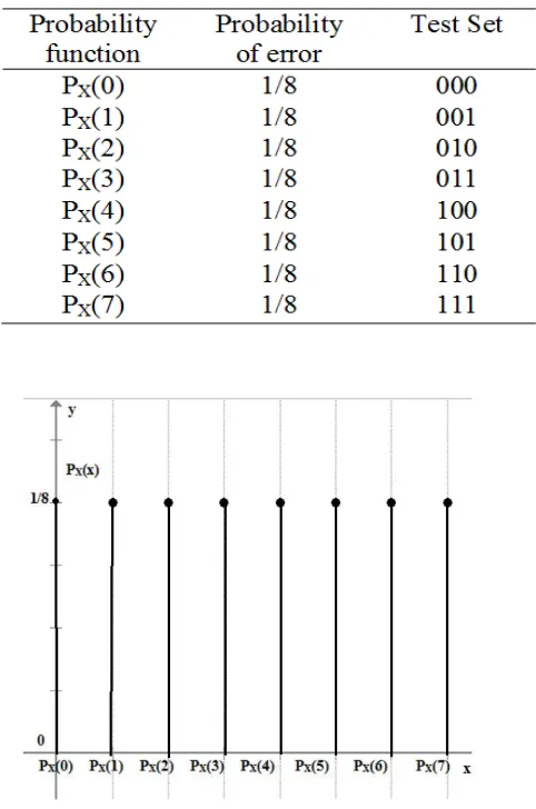
Probability mass function and probability error distribution for different test is provided in fig5 and table4. As we can assume,
X= Discrete random variable that represents the error, 0= Error, 1=No Error (10)
Probability mass function [ ( )]
Table 4 Probability of error distribution for different test sets.
fig 5 Probability mass function for Table 4.
Cumulative Distribution function (CDF)
Properties
(∞) = 1 (12)
(−∞) = 0 (13)
In table5, showed the probability sum table for test circuit (011) from which we can calculate the total probability of error by cumulative distribution graph as shown in fig6. As error occurs in= 0, 1, 2, 4, 6 as monitored in table2, the total probability of error will be:
Table5 Probability sum table for test set circuit (011)
= (0 ≤ ≤ 2) + ( = 4) + ( = 6) (14)
= ( = 2) − (0 ) + (4) − (4 ) + (6) − (6 ) (15)
3
8 − 0 +
5
8 −
4
8 +
7
8 −
6 8
=5
8= 0.625
6. Discrete random variables for 4 bit test set
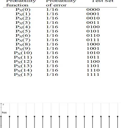
Further, for 4 bit test set the probability mass function and probability error is defined in fig7 and table6. Again we can say, X= Discrete random variable that represents the error, 0= Error, 1=No Error Probability mass function [ ( )]
Table 6 Probability of error distribution for different test set
Cumulative Distribution function (CDF)
( ) = ( ≤ ) = ( )
Properties,
(∞) = 1 ,
(−∞) = 0 (16)
We can calculate the total probability of error by cumulative distribution graph shown in fig. 8 values taken from table7. As error is occurring in= 1, 8, 9 which is monitored in table3, the total probability of error will be
fig 8. Cumulative distribution graph of probability mass function of Table 7
= ( = 1) + (8 ≤ ≤ 9) = (1) − (1 ) + (9) − (8 ) (17)
=
2
16−
1
16+
10
16−
8 16
= 3
16= 0.187
Through the above analysis, it is being stated that more the circuit variables present lesser the error probability occurs.
=5
8
= 3
16
>
This paper estimated error occurrence probability in different input variable circuits. Test set generation in the combinational circuit has been evaluated by the use of detectability concept. It is argued that more complexity of the circuit makes easier detectability. In particular, since many fault detection algorithms involve test set generation approaches, such systems with more components have more accuracy and reliability for fault detection. Overall, when we look at the results, we have calculated the probabilities with different test sets in different complexities of the circuit. Looking forward to the results we are able to state that error occurrence probability of 3-bit input variable circuit is more than the error occurrence probability of 4-bit input variable circuit. It is depicted from above estimation that the circuit having more
(18)
variable components has a minimum number of detectable and maximum numbers of undetectable error occurrence chances.
7. Conclusion
In this paper, a method for obtaining the complete test sets of all possible single stuck-at faults in a combinational circuit has been examined. An operation, detecting the stuck-at fault by test set generation using complementary logic is introduced. The detectability concept helps to detect faults present in the circuit while on the other hand undetectability in the circuit helps to avoid the detectable faults. Cumulative distribution and probability mass function are used to make the utmost chances of error occurrence. Fault occurrence probability is estimated maximum in the circuit which has a minimum number of components. The total probability of error by cumulative distribution graph shows that the error occurs in= 0, 1, 2, 4, 6 as monitored in Table 2, the total probability of error will be = =
0.625. And afterwards, we calculated that the total probability of error by the cumulative distribution
graph and error is occurring in= 1, 8, 9 which is monitored in Table 3, the total probability of error will
be = = 0.187. Through the above analysis, it is being stated that more the circuit variables present
lesser the error probability occurs. = And = . Therefore, > . And thus it is proved by the result achieved.
∝ .
These findings clearly state that the complexity of the circuit is inversely proportional to the fault occurrence probability. On the other hand, undetectability is directly proportional to the complexity of the circuit. It is concluded that a best possible circuit should have large input variable components with less complexity to minimize the faults occurrence probability.
Acknowledgment
I would wish to acknowledge EMTECH Corporation for its livelihood and many interesting conversations along the safety factor heuristic and other views of random testing. I would also like to thank the referees and editors for suggestions and additional references which improved the quality of the paper. This study has been supported by Rajiv Gandhi National Fellowship Scheme under UGC grant No.67254.
Data availability
Conflicts of Interest
The authors declare that there are no conflicts of interest regarding the publication of this paper.
References
[1] Breuer, Melvin A., Friedman, Arthur D,. Diagnosis and reliable design of digital systems. Woodland hills, California: computer science press.1976
[2] Binu D, Kariyappa B. S., A survey on fault diagnosis of analog circuits. Int. J. Electron. Communication (AEÜ) 2017; 73: 68–83.
[3] Lang S. Fault simulation for stuck-open faults in CMOS combinational circuits. A Thesis presented to the Faculty of the college of Engineering and Technology Ohio University, Athens, 1993.
[4] Majumdar A, Vrudhula S B. Techniques for Estimating Test Length under Random Test. Journal of electronic testing: Theory and Applications, 1994; 5: 285-297.
[5] Deo P.V., Two-test two-function technique for fault detection in digital combinational circuits. International Journal of Electronics 1986; 60:4, 535- 540.
[6] Friedman A. D, Menon P. R., Fault detection in digital circuits. Englewood cliffs, N. J. Prentice hall, Computer applications in electrical engineering series, 1971.
[7] Kohavi, Switching and Finite automata theory. New York: McGraw-Hill Education.1990.
[8] Guran H., Halici U., Discussion on stuck-at faults in combinational circuits, International Journal of Electronics, 67:1, 7-14, 2007
[9] Muehldorf, Savkar D. LSI logic testing-an overview. IEEE transactions on computers, 1981; 30: 1-16.
[10] Gault JW, Robinson JP, Reddy SM, Multiple fault detection in combinational networks. IEEE Transactions on Computers 1972; 21: 31-36.
[11] Wadsack RL. Fault modeling and logic simulation of CMOS and MOS integrated circuits. Bell System Technical Journal 1978; 57: 1449-1474.
[12] Agrawal VK, Fung SF. Multiple faults testing of large circuits by single fault test sets. IEEE Transactions on Computers 1981; 30: 855-865.
[13] Agrawal VK, Masson GM. Generic fault characterizations for table look-up bounding. IEEE Transactions on Computers 1980; 29: 288-299.
[14] Ubar R. Design Error Diagnosis with Re-Synthesis in Combinational Circuits. Journal of electronic testing: Theory and Applications 2003; 19: 73-82.
[15] Bartel M. Coding redundancy for combinational switching circuits. Fault-Tolerant Computing Systems: Tests, Diagnosis, Fault Treatment 5th International GI/ITG/GMA Conference Nürnberg, September 25–27, 1991.
[16] Mostafa H, Abd-el-barr. Statistical analysis of multiple intermittent faults in combinational Circuits. Journal of Electronics 1996; 80: 647- 660.
[17] Nanya, Mourad T, Mc Cluskey EJ. Stuck-at fault testability of self-testing checkers. Proceedings 18th International Symposium on Fault-tolerant Computing, Tokyo, Japan 1988; 381- 386.
[19] Marcus W, Wunderlich H.J. Incremental Computation of Delay Fault Detection Probability for Variation-Aware Test Generation. 19th IEEE European Test Symposium (ETS) 2014
[20] George M. Bounding Fault Detection Probabilities in Combinational Circuits. Journal of electronic testing: Theory and Applications, 1994; 2: 315-323.
[21] Pathak R. A generalized algorithm for bounding fault detection probabilities in combinational circuits. Autotestcon 93, San Antonio 1993; 683-689.
[22] Jin D, Jiandong H. A new probabilistic approach for estimating fault detection probability, Journal of electronics (China)1994; 11: 309-314
[23] Schneider. Implementing Fault-Tolerant Service using the state machine. ACM Computing Surveys, 1990; 22
[24] Siewiorek, Swarz R. Reliable computer system: Design and Evaluation. MA: Digital Press 1982 [25] Samia AA. A partitioning technique for reducing the computational complexity of probabilistic fault
detection in general combinational circuits. Int. J. Electronics, 1992; 72: 605-617.
[26] Reddy S, Pomeranz I, Kajihara S. Compact Test Sets for High Defect Coverage, IEEE Trans. on CAD of ICs and Systems 1997; 16: 923
[27] Sen, B., Dutta, M., Mukherjee, R. et al. J Comput Electron (2016) 15: 429
[28] Shamsujjoha, M., Hossain, F., Ali, M.N.Y. et al. J Comput Electron (2015) 14: 726.
[29] Kargar S. M., Salahshoor K., Yazdanpanah M. J., Multiple Model-Based Fault Detection and Diagnosis for Nonlinear Model Predictive Fault-Tolerant Control. Arab J Sci Eng, 2014; 39:7433– 7442.