Article
Thermal energy storage in a stovepipe using phase
change material: a numerical study
Alexis Sevault1*, Jerol Soibam2, Nils Erland L. Haugen1,2, Øyvind Skreiberg1 1 SINTEF Energy Research, P.O. Box 4761 Torgarden, NO-7465 Trondheim, Norway
2 NTNU - Norwegian University of Science and Technology, Dpt of Energy and Process Engineering, 7491 Trondheim, Norway
* Correspondence: Alexis.Sevault@sintef.no; Tel.: +47-4101-9994
Abstract: Batch combustion in wood log stoves is a promising application for latent heat storage (LHS), due to the transient heat production with high peak effects. The current study aimed at designing a compact, passive and durable LHS system storing a substantial part of the heat release during batch combustion and effectively releasing the stored heat to the room for 6 to 10 hours after the last batch. The LHS system consists of a coaxial cylinder located at the top of the wood stove, replacing part of the regular stovepipe. Internal metallic fins were applied as heat transfer enhancement to homogenize the temperature distribution inside the PCM. The effect of radial fin lengths was numerically investigated through a parametric study using five different fin lengths within the PCM. Using 35-mm fins in the 70-mm PCM layer yielded the best trade-off for the application. This configuration enabled achieving a slow but close to complete melting of the PCM within a realistic combustion duration, while avoiding overheating the PCM above its degradation temperature. Thereafter, the discharge allowed releasing the stored latent heat for 6 hours. The exhaust gas inlet temperature proved to have a strong influence on the PCM thermal performance.
Keywords: Phase Change Materials, PCM, Thermal Energy Storage, Latent Heat Storage, Wood Stove, Stovepipe
Nomenclature 𝛽 Liquid fraction
C Mushy zone constant [kg·m-3·s-1] cp Specific heat capacity [J·(kg·K)-1]
g Gravitational acceleration [m·s-2] H Specific enthalpy [J·kg-1]
h Specific sensible enthalpy [J·kg-1] href Reference specific enthalpy [J·kg-1]
k Thermal conductivity [W·(m·K)-1] K Kinetic energy [m2·s-2]
ε Dissipation rate [m2·s-2] Lf Latent heat of fusion [J·kg-1]
μ Dynamic viscosity [Pa·s]
Ti, Tf Initial and final temperatures [°C]
TS, TL Solidus and liquidus temperatures [°C]
P Pressure [Pa]
Ψ Small computational constant ρ Density [kg·m-3]
S Momentum source term [kg·m-2·s-2] V Fluid velocity [m·s-2]
Subscripts
CFD Computational fluid dynamics ESC Energy storage capacity HDPE High-density polyethylene THE Heat transfer enhancement LHS Latent heat storage PCM Phase change material TES Thermal energy storage
1. Introduction
1.1 Background
Thermal energy storage (TES) is needed whenever there is a temporal mismatch between production and demand of thermal energy. TES can be used to store heat or cold during periods of overproduction of heat or electricity, to be able to utilize it at a later point of time. A classical, and the most obvious, example is solar energy applications [1, 2]. However, TES may also be applied to reduce peak heating and cooling demands and to improve system efficiency wherever there is a variation in the availability and/or demand, on shorter or longer time scales.
Thermal energy can be stored either in the form of sensible heat, latent heat, or as thermochemical energy [3]. In a sensible heat storage, heat is stored by heating a medium with high specific heat capacity. In a thermochemical heat storage, heat is stored using reversible chemical reactions that absorb or release thermal energy. In the case of latent heat storage (LHS), heat is stored as the latent heat of phase change: melting or vaporization. Latent heat is unique in that the temperature of the material remains around the phase change temperature during the whole phase change process. A great advantage of latent heat storage is its high energy density as compared to sensible heat storage, resulting in smaller storage volumes. Their high latent heat of fusion enables PCMs to store 5–14 times more heat per unit volume than common sensible storage materials such as water, masonry, or rock [4]. Practical PCMs are materials that undergo solid-liquid transformation, i.e. a melting-solidification cycle, at around the operating temperature range of the selected thermal application [3].
Applying LHS for small-scale batch combustion is a promising concept to exploit the PCM properties. Wood log stoves, for example, rely on a batch combustion process. The latter yields a transient heat production with high peak heat release during combustion, often exceeding the actual needs of the end users. With typical thermal efficiency of 70 to 80 % at nominal load, modern wood stoves often produce more heat than actually required to heat up the house, especially in highly-insulated buildings [5]. At the end of a batch, the heat release rapidly decreases, while the need for heating may remain.
An effective LHS system, using a PCM with melting temperature within 100-150 °C, can flatten out the peak heat release to the room by storing it as latent heat. The stored heat can then be released to the room at the end of the batch combustion, through a relatively stable heat release over an extended time-period. Compared to current sensible heat storage solutions using e.g. soapstone, PCMs have the potential to yield a more efficient solution. For a given temperature range, PCM offer higher heat storage capacity both per unit mass and volume, as well as a more stable heat release due to the quasi-isothermal phase change process. These advantages are of special interest for highly-insulated low-energy buildings and passive houses. LHS systems may be designed as a retrofit to existing wood stoves or as an integrated and optimized add-on to new wood stoves. However, designing an optimal system with a suitable PCM remains challenging due to the complexity of the physical and thermal interactions between PCM, heat source and heat sink and the transient nature of wood stoves.
1.2 Objective
The investigation aimed at designing a compact and durable LHS system with the ability to store a significant part of the heat release during batch combustion and to effectively and slowly release the stored heat to the room at the end of the combustion duration. The LHS was designed as a passive system based on a coaxial cylinder wrapped around a stovepipe located at the top of a wood stove. Numerical modelling was performed using transient two-dimensional axisymmetric CFD modelling with ANSYS FLUENT 17.2. A parametric study was realized with regards to the system's thermal performance using as parameters fin length and exhaust gas inlet temperature.
1.3 Literature review
A large variety of PCMs are available today, with a high number of thermo-chemical properties affecting their suitability to a given application. Kristjansson et al. [6] developed a method to assist the optimal PCM selection for LHS with wood stove combustion, based on a one-dimensional analysis. The results enable to describe the LHS performance through key indicators, e.g., energy density, ratio of latent to sensible heat capacity and risk of overheating. The key indicators allow effective ranking of PCMs for a given application.
Al-Abidi et al. [7, 8] reported on a successful numerical and experimental study of a LHS system based on a concentric cylinder and applied to a liquid desiccant air-conditioning system. They used a triplex tube heat exchanger with internal and external longitudinal fins. The PCM, with phase change within 77-85 °C, was enclosed between the two concentric cylinders. The effect of fin thickness was shown to be limited compared to the fin length and number of fins, whose impact was strong on the required duration for complete melting and solidification.
Almsater et al. [9] presented an experimentally validated CFD model of a similar LHS in a vertical triplex tube in a lower temperature range. Water was used as a PCM between the two concentric cylinders, while a heat transfer fluid circulated in the outer and inner tubes. The configuration used eight longitudinal fins to divide the PCM into compartments. The time for complete melting was found to be generally quicker than for complete solidification, due to the effects of free convection enhancing the melting process.
The literature is scarce regarding TES concepts associated to wood stoves. A CFD-based methodology was developed by Benesch et al. [10] to analyse and optimize wood log stoves using sensible heat storage. Various heat storage materials in solid state were then tested. Thereafter, the research group developed guidelines for heat storage solutions using PCMs applied to wood log stoves [11]. A key conclusion indicated that, to allow effective heat storage at partial combustion load, the PCM melting temperature should not be too high. The following criteria were listed as both essential and challenging for LHS systems applied to wood log stoves: low flammability, low thermal degradation, high heat capacity, high density, suitable melting temperature, affordability, low corrosivity and low toxicity. The guidelines strongly advised a full integration of the LHS unit by the side(s) of the stove, allowing the circulation of exhaust gas through the PCM, while discharging latent heat using air channels and free convection.
In a study involving a wood stove manufacturer, Zielke et al. [12] designed and experimentally tested a stove surrounded by plates filled with salt hydrates melting at 60 °C. The ultimate goal was to avoid the high emissions released when firing the stoves at partial load at night, while keeping the house warm. Though the results were promising, achieving a commercial design in line with the customers' expectations has proved difficult.
2. Materials and Methods
2.1 Numerical modelling of solid-liquid phase change 2.1.1 Moving boundary problems
Phase change processes exhibit a transient and non-linear behavior with a moving liquid-solid interface and involve flow patterns that are associated with heat transfer in fluids. The heat transfer problem in melting and solidification processes is called the moving boundary problems. It is especially complex since the solid-liquid boundary moves depending on the speed at which the latent heat is absorbed or lost at the boundary. In practice, phase change occurs over a temperature range, forming a so-called mushy zone (two-phase zone) between liquid and solid. The most widely used numerical method used to effectively model the phase change is the enthalpy formulation method [13].
Using the enthalpy formulation method, the enthalpy is considered as a temperature-dependent variable and the flow of the latent heat is expressed in terms of volumetric enthalpy as a function of a temperature of the PCM. The enthalpy formulation is one of the most popular fixed-domain methods for solving a Stefan problem. The major advantage is that the method does not require explicit treatment of the moving boundary. To introduce the formulation, the enthalpy function H is defined as a function of temperature over the fixed domain as given by Voller [14]. This method assumes that enthalpy is a sum of sensible and latent heat:
𝐻(𝑇) = ℎ(𝑇) + 𝐿 ∙ 𝛽(𝑇) (1)
Where h(T) is the sensible enthalpy:
ℎ(𝑇) = ℎ (𝑇 ) + 𝑐 ∙ 𝑑𝑇 (2)
and href is the reference enthalpy at the initial temperature Ti. β is the liquid fraction during the phase
change between solid and liquid states and it can be expressed as:
𝛽 = ⎩ ⎨
⎧ 0, if 𝑇 ≤ 𝑇 (solid) 1, if 𝑇 ≥ 𝑇 (liquid) 𝑇 − 𝑇
𝑇 −𝑇 , if 𝑇 ≥ 𝑇 ≥ 𝑇 (mushy)
(3)
An essential feature of the enthalpy method is that the conduction equation is valid for both the solid and liquid phases as well as for the solid-liquid interface and hence, there is no need to track the position of the phase change front [15]. The main advantages of this procedure are:
The equation is directly applicable for the two phases and the mushy zone.
The temperature is determined at each point and the thermo-physical properties can be evaluated.
By only observing the temperature field, the position of the two boundaries can be tracked.
2.1.3 Governing equations used in ANSYS FLUENT
The LHS system was modelled using ANSYS FLUENT 17.2. The CFD code is based on the finite volume method and allows for phase change simulations of PCM through the enthalpy porosity method. This means that instead of tracking the liquid-solid front explicitly, the liquid-solid mushy zone (partially solidified region) is treated as a porous zone. The porosity in each cell is set equal to the liquid fraction in that cell, which indicates the fraction of the cell volume that is in liquid form. The liquid fraction is computed at each iteration, based on an enthalpy balance [16]. The continuity, momentum, and energy equations are given below:
Energy equation:
𝑑(𝜌 ∙ 𝐻)
𝑑𝑡 + ∇ 𝜌 ∙ 𝑉⃗ ∙ 𝐻 = ∇(𝑘 ∙ ∇𝑇) (4)
Continuity equation:
𝑑𝜌
𝑑𝑡+ ∇(𝜌 ∙ 𝑉⃗) = 0 (5)
Momentum equation:
𝜕 𝜌 ∙ 𝑉⃗
𝜕𝑡 + ∇ 𝜌 ∙ 𝑉⃗ ∙ 𝑉⃗ = −∇𝑃 + 𝜇 ∙ ∇ 𝑉⃗ + 𝜌 ∙ 𝑔⃗ + 𝑆⃗ (6) Where V is the fluid velocity, ρ is the density, k is the thermal conductivity, μ is the dynamic viscosity, P is the pressure, g is the gravitational acceleration and S is the momentum source term. The momentum source term S, detailed by Al-Abidi et al. [7], is defined as:
𝑆⃗ =𝐶(1 − 𝛽)
The source term corresponds to the damping term in Darcy’s law, and it is added to the momentum equation due to the phase change effect on convection. The term in front of the velocity in Equation (7) is the porosity function, defined by Brent et al. [17] to make the momentum equations behave similarly to the Carman-Kozeny equations for flows in porous media. The liquid fraction β is defined in Equation (3). The mushy zone constant, C, reflects the kinetic processes in the mushy zone morphology. It describes how steeply the velocity is reduced to zero when the material solidifies, and this constant is varied between 104 and 107. Higher or lower C values may lead to unphysical oscillations in the results. A small computational constant, Ψ = 0.001, is used to prevent division by zero.
Since the mushy zone constant is an essential parameter to accurately model the melting processes involving convection, simulations were first carried out with a simplified 2D model and several C values within the above-mentioned range. The smallest value of C (104) induced unstable and unphysical results. For C ≥ 106, the influence of buoyancy was fully dampened, leading to a fully conduction-driven melting process. A C value of 105 enabled convective effects to play a major role in the melting processes and was also the value of choice in the literature within the same temperature range [8]. Therefore C = 105 was kept for all simulations.
2.2 Geometry
A heat exchanger based on two concentric pipes seemed the most promising geometry for our purpose of replacing part of the regular stovepipe above the wood stove. The PCM, located between the two concentric pipes, can be heated up by the hot exhaust gas flowing through the vertical inner pipe from bottom to top, while the heat is slowly released to the surroundings.
In the stainless-steel concentric pipes, the inner pipe has an outer diameter of 150 mm, and the outer pipe has an outer diameter of 300 m. The wall thickness for both pipes is 5 mm, leaving a 70-mm thick layer of PCM between the pipes. A pipe length of 300 70-mm was kept for the CFD simulation to represent a more acceptable total weight and to reduce the computing time. The 3-mm stainless-steel fins in the PCM volume are radial and located all around the inner pipe, see Figure 1.
Although longitudinal fins may effectively enhance the PCM melting rate in similar geometries [8], radial fins enable a more homogeneous melting process along the concentric pipes. Radial fins provided the opportunity to model the LHS system using 2D-axisymmetry, resulting in shorter computing time than any 3D model with longitudinal fins.
Figure 1. (a) Concentric pipes modelled in ANSYS FLUENT. Hot exhaust gas flows through the inner pipe from bottom to top. (b) Top view of the coaxial cylinder for a radial fin cross section.
Preliminary CFD simulations with constant wall temperature and no flowing hot exhaust gas evaluated the optimal radial fin number and separation distance in the PCM domain, from no fin to three fins equally distributed along the 300-mm long coaxial cylinder [18, 19]. A more homogeneous heat transfer across the PCM was achieved with three equidistant radial fins, which were therefore kept for all simulations (see Figure 1).
2.3 Material and fluid properties
Considering the hot exhaust gas of batch wood log combustion ranging from 100 °C to 300 °C, the PCM Erythritol was considered due its melting temperature at 118 °C. The computed thermo-physical properties of Erythritol are shown in Table 1. Properties indicated for two temperatures were modelled in ANSYS FLUENT using piece-wise linear equations.
Table 1. Thermo-physical properties of the PCM Erythritol based on [20-22]. Erythritol properties Values used in simulations Melting temperature 117-120 °C
Theoretical degradation temperature 160 °C Latent heat of fusion 339.9 kJ·kg-1 Specific heat capacity (solid, 20 °C) 1.38 kJ·(kg·K)-1 Specific heat capacity (liquid, 140 °C) 2.76 kJ·(kg·K)-1 Conductivity (solid, 20 °C) 0.733 W·(m·K)-1 Conductivity (liquid, 140 °C) 0.326 W·(m·K)-1
Density (solid, 20 °C) 1480 kg·m-3 Density (fluid, 140 °C) 1300 kg·m-3
Erythritol is known to degrade through decomposition from 160 °C [21], while in practice its thermal properties may be altered at even lower temperatures. The thermo-physical properties of Erythritol can however yield high thermal performance for the current application.
The thermo-physical properties of the hot exhaust gas are shown in Table 2, calculated at 225 °C using GASEQ [23] based on the following composition: 7 % CO2, 13 % O2, 20 % H2O and 60 % N2, which is a representative mean composition of wood stove exhaust gas.
Table 2. Exhaust gas properties at 225 °C with a composition of 7 % CO2, 13 % O2, 20 % H2O and 60 % N2.
Hot exhaust gas properties Values used in simulations
Density 0.72 kg·m-3
Specific heat capacity 1155 J·(kg·K)-1 Viscosity 2.46·10-5 kg·(m·s)-1 Conductivity (pure gas) 0.035 W·(m·K)-1 Equivalent thermal conductivity with HTE 2.45 W·(m·K)-1
Preliminary calculations showed that the heat transfer rate from the hot exhaust gas towards the PCM through the inner pipe was insufficient without using any heat transfer enhancement (HTE). Thus, eight longitudinal fins were considered on the hot exhaust gas side to enhance the heat transfer towards the inner pipe (see Figure 1). In the CFD calculations, the fins are simulated through the calculated volume-averaged effective heat conductivity of the hot exhaust gas of 2.45 W·(m·K)-1 instead of 0.035 W·(m·K)-1 for the pure hot gas.
The 2D-axisymmetrical geometry and mesh were created in ANSYS DesignModeler and imported to ANSYS FLUENT 17.2. Transient simulations were run using a gravity of 9.81 m·s-2. Due to the solid-liquid phase change, sharp gradients were expected locally. To have a smooth increment in mesh size in the near wall region, the inflation option with smooth transition was used with transition ratio of 0.054 and a growth rate of 1.02 in the PCM domain. A mesh sensitivity analysis yielded an effective resolution of the gradients using a maximum cell size of 1 mm for both the hot gas and the PCM domain, with smaller element size near the walls. The total number of finite elements in the mesh amounted to about 65 000.
2.5 Initial and boundary conditions
During the charge (melting), to simulate the hot exhaust gas flowing through the stovepipe, the inlet boundary in the gas domain was set to a velocity-inlet with a value of 1 m·s-1 and a constant inlet temperature of 225 °C. The outlet boundary in the gas domain was set as an outlet-vent. The outer pipe wall towards the room was set to have heat losses outward through convection and radiation. The corresponding heat transfer coefficient for convection was set to 25 W·m-2·K-1 with a free-stream temperature of 298 K. The coefficient was chosen higher than for regular free convection to account for the effect of the convective air flows originating from the hot wood stove underneath the stovepipe. For the radiation, the wall emissivity was set to 0.85. The bottom and top walls of the PCM domain were defined as adiabatic walls. The whole LHS system temperature was initiated to 298 K.
Since the Reynolds number for the hot exhaust gas was within the turbulent regime for a pipe flow, the K-epsilon model was used in the inner pipe. Considering a turbulent intensity of 5 % in the pipe at the inlet, the kinetic energy and dissipation rate yielded K = 0.375 m2·s-2, ε = 3.59 m2·s-2, with a minimum wall distance of 0.0054 mm.
Regarding the discharge (solidification), the inlet and outlet boundaries in the hot exhaust gas domain were assigned adiabatic walls, as if a virtual valve blocked the gas flow in the stovepipe once the batch combustion process ended. In practice, the gas flow would not be completely blocked in order to evacuate the residual exhaust gas from the charcoal burnout phase. The simplification minimized the heat losses through the inner pipe while easing the comparison between the tested cases. The hot gas domain was patched at 100 °C as initial condition for the discharge, a relatively high temperature though still below the melting temperature of the PCM. Two different initial conditions were studied in the PCM domain for the discharge: (1) starting from a homogeneous temperature of 122 °C, just above the PCM melting temperature and (2) starting from the liquid fraction and temperature fields as established after 6 h of charge, to emulate a dynamic case with sudden change of boundary conditions.
2.6 Parametric analysis
Five fin lengths, in perfect contact with the inner pipe in the PCM domain, were tested under the described conditions. The five lengths corresponded to zero (no fins), 17.5 mm (one quarter of the PCM layer), 35 mm (half-way through the PCM layer), 52.5 mm (three quarters of the PCM layer) and 70 mm (joining the inner pipe to the outer pipe). The configuration with 70-mm fins yielded the lowest packing factor with 97 % volume occupied by the PCM, considering 100 % with no fins. The parametric analysis enabled to understand the effects of fin length on melting and solidification processes and to determine the most relevant fin length for the given application with wood stoves.
Based on these specifications, theoretical key performance indicators have been calculated for the five configurations, as shown in Table 3. The energy storage capacity (ESC) was calculated considering a temperature range between 25 °C and 150 °C, including the system components yielding sensible heat storage (i.e. fins and metallic pipes). The system is designed for a wood stove with a nominal power of 8-12 kW, with ca. 2.9 kW heat flow in the flue gas.
Table 3. Key performance indicators for various fin lengths.
Packing factor 100 % 99 % 99 % 98 % 97 % Theoretical LHS system weight [kg] 30.6 31.1 31.7 32.5 33.3 Energy storage capacity (ESC) PCM [kWh] 3.47 3.45 3.43 3.40 3.37 ESC Components [kWh] 0.130 0.140 0.153 0.168 0.184
ESC System [kWh] 3.60 3.59 3.58 3.57 3.55
Ratio of latent heat to ESC system 58.9 % 58.7 % 58.5 % 58.2 % 57.9 %
2.7 Numerical parameters for converged solutions
The temperature range between solidus and liquidus temperatures was set to 3 K, centered on 118 °C. This enabled sufficient calculation stability, while narrower temperature ranges did not. Note that the mushy zone constant, C, is to some extent dependent on the temperature range between solidus and liquidus temperatures, as shown by [24].
In the solution method, the PRESTO scheme was used for the pressure correction equation and the Semi-Implicit Pressure-Linked Equation (SIMPLE) algorithm for the pressure-velocity coupling. Momentum, turbulent kinetic and energy equations were computed using the first-order scheme. To enable converged solutions, the relaxation factors were set to 0.1 for liquid fraction, 0.3 for pressure and momentum, 0.8 for density, turbulent kinetic energy and turbulent dissipation rate, 0.9 for energy and 1 for body forces.
A sensitivity analysis on the calculation time step revealed that 1 s was a sufficiently small time step to simulate the behavior of the PCM during the melting process. However, a time step of 0.5 s was preferred to effectively capture the solidification process.
3. Results and discussion
3.1 Liquid fraction
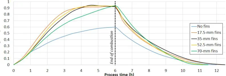
Figure 2 shows the effect of the fin length on the mass-averaged liquid fraction for 6 h of charge (melting) followed by a discharge (solidification). A duration of 6-h represents an average combustion duration with several consecutive wood-log batches. Thereafter, the discharge was triggered by a change of boundary conditions in the inner pipe. Pursuing simulations of charge only (melting) with the 70-mm fins showed that it took up to 11.5 h to fully melt the PCM, while none of the other tested fin configurations reached complete melting. In Figure 2, the liquid fraction with the 70-mm fins lies below the other configurations with fins until 6 h into the charge, where all fin configurations reached a liquid fraction within 0.92 - 0.94. The geometry with no fins did not yield melting beyond 60 % within 6 h.
Figure 2. Effect of fin length on liquid fraction for 6 h of charge (melting) followed by a discharge (solidification).
transfers, whose relative significance varies with the fin length and the fraction of melted PCM over time.
After about 4 h, the liquid fraction for the 35-mm fins reached a local maximum and then slightly decreased instead of following an expected increasing or flattening trend. A similar effect was observed for the case with 52.5-mm fins after 5 h, though to a minor extent. This is due to the free convection, transporting the hot melted PCM through buoyancy to the top of the pipe, while the cooler melted PCM was transported toward the bottom. It eventually yielded a sufficient vertical temperature gradient, cooling down the lower part of the PCM block, below the PCM melting temperature. The effect was amplified by the continuous heat release by radiation and convection to the room, for an ambient temperature of 25 °C. This local re-solidification phenomenon could be clearly observed in the lower part of the PCM volume in a 2D animated visualization of the liquid fraction during the charge.
During the discharge, the configuration with 70-mm fins yielded a significantly higher rate of solidification than all the other tested cases, while the case without fins showed the lowest rate of solidification. With 70-mm fins, the PCM was fully solidified after 5 h, followed by the case with the 52.5-mm fins in 5.5 h, no fins in 6 h and 17.5-mm and 35-mm fins in 6.5 h.
The liquid fraction in the 2D axisymmetric model can be observed in Figure 3 after 1 h of charge, for the five tested fin lengths. The effects of buoyancy, yielding free convection, were visible through the melted PCM accumulating under the fins. For the cases with 17.5-mm and 35-mm fins, the melted PCM reached a sufficient volume to pass beyond some of the fins after 1 h of charge. Without fins, the free convection effects transported a noticeably higher melted fraction in the upper part of the PCM domain, along the inner pipe. In comparison, the distribution of melted PCM was more homogeneous along the vertical axis in configurations with fins.
Figure 3. Effect of fin length on liquid fraction, 1 h after start of melting process.
Figure 4. Effect of fin length on liquid fraction, 1 h after start of solidification (starting from full liquid state).
The liquid fraction in the 2D axisymmetric model after 1 h of discharge is shown in Figure 4 for the five tested fin lengths. The solidification process naturally progressed from the outer pipe wall since it was in contact with the room maintained at 25 °C. The level of solidification with 70-mm fins after 1 h was significantly higher than for the other cases.
One can observe that the mushy zone was significantly broader during the solidification process than during the melting process. The narrow mushy zone visible in Figure 3 during melting was shaped by the convective heat transport that was playing a major role, while solidification is rather conduction-driven, with nearly no convective transport of melted PCM [3]. This effect tends to broaden the mushy zone where the PCM is in a slurry state, neither fully liquid nor solid. The thickness of the mushy zone during solidification might also be artificially amplified by the mushy zone constant, which was evaluated with regards to the PCM melting process and kept constant for the solidification process for the continuity.
3.2 Heat transfer to the surroundings
The effect of fin length on the heat transferred by radiation and convection from the outer pipe to the room is shown in Figure 5 for 6 h of charge (melting) followed by a discharge (solidification). The interplay of convective and conductive heat transfers in the PCM with 17.5-mm, 35-mm and 52.5-mm fins interestingly yielded a higher heat output to the room from 2.5 h (3.5 h for 35-52.5-mm) up to 5 h of charge compared to the case with 70-mm fins. A thermal balance was nearly reached after 4.5 h for the configurations with 17.5-mm, 35-mms and 52.5-mm fins, when the amount of transferred heat reached a plateau.
Figure 5. Effect of fin length on the heat transferred from the outer pipe to the room for 6 h of charge (melting) followed by a discharge (solidification).
The heat loss to the inner pipe during the discharge was minimized by the blockage of the gas flow in the inner pipe. During the discharge, the 70-mm fins yielded the highest heat release to the room and the highest solidification rate. With this configuration, the change of gradient during the first hour of discharge indicated the change between sensible heat transfer dominating first, followed by latent heat transfer. The configuration with no fins achieved the lowest solidification rate, though the total heat available was naturally lower than for the other cases since a lower fraction of PCM was melted after 6 h.
The heat transferred to the room from the outer pipe was dominated by convection over radiation. One should consider that the convective heat transfer coefficient of 25 W·m-2·K-1 for the outer pipe wall towards the room was probably over-estimated. A coefficient closer to regular free convection, within 5-10 W·m-2·K-1, would be more realistic and yield a slower solidification rate by reducing the heat loss to the room. An alternative model could allow the convection coefficient to decrease with time, to consider the transient influence of the hot air transported by convection around the hot stove. Due to the large thermal inertia of the wood stoves, such convective flows are typically large during the combustion duration and slowly decrease over time as the wood stove walls cool down after combustion ends.
3.3 Exhaust gas outlet temperature
Figure 6 shows the average temperature at the exhaust gas outlet for the tested fin configurations, during the 6-h charge. In all cases, the exhaust gas temperature was kept above the water condensation temperature range. For the configurations with fins, the outlet temperature reached a near-plateau after only about 15 minutes, slightly increasing over the melting process as the PCM bulk temperature increased. The stabilization occurred at ca. 165 °C, yielding a temperature difference of 60 °C between inlet and outlet. For the case with no fins, a local maximum can be observed after ca. 25 minutes, due to the liquefaction of PCM along the walls. Liquid Erythritol's thermal conductivity is less than half of the one of solid Erythritol, and therefore provides higher thermal resistance. Once the liquid PCM reached the critical thickness along the wall to initiate free convection, the heat removal from the exhaust gas increased again, stabilizing the exhaust gas temperature at ca. 165 °C. In the case with 70-mm fins, the exhaust gas temperature at the outlet kept increasing. In this case, the free convection in the PCM steadily got less intense since the PCM cells were surrounded by highly-conductive metallic walls connected together, reducing the temperature differences required to sustain convective heat transport.
Note that the visible fluctuations in Figure 6 were mostly due to the large time steps used for the calculations with regards to the high gas velocity (1 m·s-1 at the inlet). These fluctuations did not affect the calculations on the PCM side and therefore were neglected.
3.4 Sensitivity to exhaust gas inlet temperature
Based on the configuration with 35-mm fins, a sensitivity analysis was carried out on the exhaust gas temperature at the inlet during the 6-h charge. In addition to 225 °C, exhaust gas inlet temperatures of 175 °C and 275 °C were tested. The corresponding mass-averaged liquid fraction, as shown in Figure 7, revealed a strong variation in system behavior. Using 175 °C, the PCM melted to only about 70 % within 6 h. Using 275 °C, the whole PCM volume melted within 2.2 h, without showing any sign of local re-solidification phenomenon.
The integrated heat flux from the outer wall to the room, shown in Figure 8, revealed an expected low and monotonic heat transfer to the room with 175 °C. With 275 °C, the heat transfer to the room showed a steep increase until the PCM was fully melted after ca. 2.2 h. Beyond that time, the heat flux kept on increasing, though with a lower gradient.
The temperature of the exhaust gas at the outlet, shown in Figure 9, stabilized at ca. 140 °C with an inlet temperature of 175 °C, yielding a temperature difference of 35 °C between inlet and outlet. With 275 °C as inlet temperature, the outlet temperature first stabilized until the bulk PCM was fully melted, then abruptly increased, and thereafter increased with a lower gradient.
The temperature of the exhaust gas at the inlet is an essential parameter to assess the durability of the system. In practice, due to the nature of wood batch combustion, this temperature rapidly varies with time and may reach up to 275 °C and beyond, though for a limited time. The exhaust gas composition can rapidly vary with time as well. It would be of high interest to study the influence of such transient profiles on the stovepipe configuration to evaluate the system's thermal performance at partial load, the impact on heat transfer to the room and the maximum local PCM temperature.
Figure 7. Mass-averaged liquid fraction of the PCM Erythritol for three exhaust gas inlet temperatures.
Figure 9. Average exhaust gas temperature at the outlet for three exhaust gas inlet temperatures.
3.5 Optimal configuration with regards to the application
The objective was to achieve a slow and close to complete melting of the PCM within a realistic combustion duration, e.g. 6 h, while avoiding overheating the PCM beyond its degradation temperature. Thereafter, the discharge should provide a slow heat release of the stored latent heat within 6 to 10 hours.
Among the five tested configurations, the four cases with fins clearly outperformed the case with no fins, as shown in Figure 10. The configuration with 35-mm fins provided the best trade-off for our application by charging the system within only 4.5 h and then nearly reaching a thermal balance. The bulk PCM was kept below the degradation temperature. Though 70-mm fins yielded a significantly higher heat release to the room during the discharge, the early heat loss to the room during the charge and the local overheating (up to 166 °C) of the PCM were a disadvantage.
The degradation temperature of the PCM Erythritol is visibly low for batch combustion applications displaying highly transient temperatures. The maximum temperatures in the hot exhaust gas can be potentially higher than those tested here. Supercooling of PCM Erythritol was not implemented in the CFD simulations though it was reported in the literature [20]. In the view of the large temperature differences experienced by the system, the problem was assumed to be minor. Experimental validation tests would be of interest to confirm this assumption. Another PCM may be considered in further studies such as high-density polyethylene (HDPE) [25, 26].
Figure 10. Heat energy released during melting and solidification for the studied fin configurations (left-y-axis), as well the corresponding maximum local PCM temperature during melting (right-y-axis). PCM Erythritol degradation temperature is indicated, corresponding to the right-y-axis.
Conclusions
The LHS was designed as a passive system based on a coaxial cylinder wrapped around a stovepipe located at the top of a wood stove. Numerical modelling was performed using transient two-dimensional axisymmetric CFD modelling with ANSYS FLUENT 17.2. The system was equipped with internal radial metallic fins to enhance thermal conductivity and homogenize the temperature distribution inside the PCM. A parametric study was realized with regards to the system's thermal performance using as parameters fin length and exhaust gas inlet temperature.
Regarding the number of fins and the distance between them, configurations with three equidistant radial fins along the 300-mm long inner pipe provided a homogeneous heat distribution in the PCM. Using 35-mm fins in the 70-mm PCM layer yielded the most effective results, with a slow but close to complete melting of the PCM within a realistic combustion duration, while avoiding overheating the PCM beyond the degradation temperature. Then the discharge allowed a slow heat release of the stored latent heat for 6.5 h.
The exhaust gas outlet temperature stabilized for all cases within 160-170 °C during the charge. The sensitivity to the exhaust inlet temperature was analyzed and showed that it had a significant impact on the system's thermal performance and maximum local PCM temperature.
A few recommendations were pointed out along the discussion of the results, notably the need to study more advanced fin configurations and the strong sensitivity to exhaust gas inlet temperature, which will vary through the batch combustion, together with the exhaust gas composition. Another remaining challenge is the thermal degradation of erythritol, occurring only 42 °C, or less, above the PCM melting temperature and endangering the durability of a practical LHS system. This critical temperature may be reached due to the highly transient combustion behavior of the batch-combustion stoves, especially throughout several consecutive batches.
The mushy zone constant plays a major role in the modelling of melting processes due to its influence on the local convection effects enhancing the melting of the PCM, as well as on the thickness of the mushy zone during solidification. Experimental validations would allow a finer tuning of this constant while offering a practical insight into the thermal performance of the LHS system.
Author Contributions: Conceptualization, Alexis Sevault and Øyvind Skreiberg; Methodology, Alexis Sevault and Nils Erland L. Haugen;
Formal Analysis, Alexis Sevault and Jerol Soibam;
Resources, Alexis Sevault and Øyvind Skreiberg;
Data Curation, Alexis Sevault, Jerol Soibam Øyvind Skreiberg and Nils Erland L. Haugen; Writing-Original Draft Preparation, Alexis Sevault;
Writing-Review & Editing, Alexis Sevault, Øyvind Skreiberg and Nils Erland L. Haugen; Visualization, Alexis Sevault and Jerol Soibam;
Supervision, Alexis Sevault and Nils Erland L. Haugen; Project Administration, Alexis Sevault;
Funding Acquisition, Alexis Sevault.
Funding: The current study was carried out through the research competence-building project PCM-Eff supported by SINTEF Energy Research using basic funding of the Research Council of Norway. The project aims at investigating novel phase change material solutions for efficient thermal energy storage at low and medium-high temperature (https://www.sintef.no/en/projects/pcm-eff/).
Conflicts of Interest: The authors declare no conflict of interest. The funders had no role in the design of the study; in the collection, analyses, or interpretation of data; in the writing of the manuscript, and in the decision to publish the results.
References
1. Gil, A.; Medrano, M.; Martorell, I.; Lázaro, A.; Dolado, P.; Zalba, B.; Cabeza, L.F., State of the art on high temperature thermal energy storage for power generation. Part 1—Concepts, materials and modellization. Renewable and Sustainable Energy Reviews, 2010, 14(1): p. 31-55 DOI: http://doi.org/10.1016/j.rser.2009.07.035. 2. Hoshi, A.; Mills, D.R.; Bittar, A.; Saitoh, T.S., Screening of high melting point phase change materials (PCM) in solar thermal concentrating technology based on CLFR. Solar Energy, 2005, 79(3): p. 332-339 DOI: 10.1016/j.solener.2004.04.023.
3. Fleischer, A.S., Thermal energy storage using phase change materials: fundamentals and applications. Springer. 2015.
4. Sharma, A.; Tyagi, V.V.; Chen, C.R.; Buddhi, D., Review on thermal energy storage with phase change materials and applications. Renewable and Sustainable Energy Reviews, 2009, 13(2): p. 318-345 DOI:
http://dx.doi.org/10.1016/j.rser.2007.10.005.
5. Georges, L.; Skreiberg, Ø.; Novakovic, V., On the proper integration of wood stoves in passive houses: Investigation using detailed dynamic simulations.Energy and Buildings, 2013, 59(Supplement C): p. 203-213 DOI: https://doi.org/10.1016/j.enbuild.2012.12.034.
6. Kristjansson, K.; Næss, E.; Skreiberg, Ø., Dampening of wood batch combustion heat release using a phase change material heat storage: Material selection and heat storage property optimization.Energy, 2016, 115, Part 1: p. 378-385 DOI: http://dx.doi.org/10.1016/j.energy.2016.08.071.
7. Al-Abidi, A.A.; Mat, S.; Sopian, K.; Sulaiman, M.Y.; Mohammad, A.T., Numerical study of PCM solidification in a triplex tube heat exchanger with internal and external fins.International Journal of Heat and Mass Transfer, 2013, 61: p. 684-695 DOI: https://doi.org/10.1016/j.ijheatmasstransfer.2013.02.030. 8. Al-Abidi, A.A.; Mat, S.; Sopian, K.; Sulaiman, M.Y.; Mohammad, A.T., Internal and external fin heat transfer
enhancement technique for latent heat thermal energy storage in triplex tube heat exchangers.Applied Thermal Engineering, 2013, 53(1): p. 147-156 DOI: https://doi.org/10.1016/j.applthermaleng.2013.01.011. 9. Almsater, S.; Alemu, A.; Saman, W.; Bruno, F., Development and experimental validation of a CFD model
for PCM in a vertical triplex tube heat exchanger.Applied Thermal Engineering, 2017, 116: p. 344-354 DOI:
10. Benesch, C.; Blank, M.; Scharler, R.; Kössl, M.; Obernberger, I. Transient CFD Simulation of Wood Log Stoves with Heat Storage Devices. 21st European Biomass Conference and Exhibition. 2015.
11. Mandl, C.; Obernberger, I., Guidelines for heat storage units based on Phase Change Materials (PCM), in
Project "Woodstoves2020", Bioenergy, E.-N., Editor. 2017.
12. Zielke, U.; Bjerrum, M.; Nørgaard, T., Slow Heat Release - Brændeovn med salthydratvarmelager - Miljøprojekt nr. 1438, Institut, T., Editor. 2013.
13. Comini, G.; Del Guidice, S.; Lewis, R.W.; Zienkiewicz, O.C., Finite element solution of non-linear heat conduction problems with special reference to phase change.International Journal for Numerical Methods in Engineering, 1974, 8(3): p. 613-624 DOI: 10.1002/nme.1620080314.
14. Voller, V.R., Fast implicit finite-difference method for the analysis of phase change problems.Numerical Heat Transfer, Part B: Fundamentals, 1990, 17(2): p. 155-169 DOI: 10.1080/10407799008961737.
15. Özişik, N., Finite Difference Methods in Heat Transfer, ed. Press, C.: Taylor & Francis. 1994. 432. 16. ANSYS, Fluent Theory Guide, Release 16.1. 2015.
17. Brent, A.D.; Voller, V.R.; Reid, K.J., Enthalpy-porosity technique for modeling convection-diffusion phase change: Application to the melting of a pure metal.Numerical Heat Transfer, 1988, 13(3): p. 297-318 DOI: 10.1080/10407788808913615.
18. Sevault, A.; Soibam, J.; Haugen, N.E.L.; Skreiberg, Ø., Investigation of an Innovative Latent Heat Storage Concept in a Stovepipe.Chemical Engineering Transactions, 2018, 65.
19. Soibam, J., Numerical Investigaton of a Phase Change Material Heat Exchanger for Small-Scale Combustion Appliances. Master Degree, Norwegian University of Science and Technology - NTNU, Trondheim, Norway, 2017.
20. Höhlein, S.; König-Haagen, A.; Brüggemann, D., Thermophysical Characterization of MgCl(2)·6H(2)O, Xylitol and Erythritol as Phase Change Materials (PCM) for Latent Heat Thermal Energy Storage (LHTES). Materials, 2017, 10(4): p. 444 DOI: 10.3390/ma10040444.
21. Kaizawa, A.; Maruoka, N.; Kawai, A.; Kamano, H.; Jozuka, T.; Senda, T.; Akiyama, T., Thermophysical and heat transfer properties of phase change material candidate for waste heat transportation system.Heat and Mass Transfer, 2008, 44(7): p. 763-769 DOI: 10.1007/s00231-007-0311-2.
22. Mehling, H.; Cabeza, L.F., Heat and cold storage with PCM. Springer, Berlin, Heidelberg. 2008. 23. Morley, C., Gaseq. 2005.
24. Kheirabadi , A.C.; Groulx, D., Simulating phase change heat trasnfer using Comsol and Fluent: Effect of the mushy-zone constant.2015, 7(5-6): p. 427-440 DOI: 10.1615/ComputThermalScien.2016014279. 25. Gasia, J.; Tay, N.H.S.; Belusko, M.; Cabeza, L.F.; Bruno, F., Experimental investigation of the effect of
dynamic melting in a cylindrical shell-and-tube heat exchanger using water as PCM.Applied Energy, 2017, 185, Part 1: p. 136-145 DOI: http://doi.org/10.1016/j.apenergy.2016.10.042.
![Table 1. Thermo-physical properties of the PCM Erythritol based on [20-22].](https://thumb-us.123doks.com/thumbv2/123dok_us/1029469.1603108/6.612.154.457.275.406/table-thermo-physical-properties-pcm-erythritol-based.webp)