A
Motion
Planning
Model
for
Simulating
a
Virtual
Crowd
Muzhou
Xiong,
Shanyu
Tang
School
of
Computer
Science,
China
University
of
Geosciences,
Wuhan
430074
email:
Abstract
Hence, a rule-based model is applied to simulate how the agent makes a response and recovers from the collision. Simulation results from the case study indicate that the proposed motion planning method can be adapted to different what-if simulation scenarios and to different types of pedestrians. The performance of the model has been proven to be efficient.
-Keywords: Motion planning, collision avoidance, collision response, agent-
based simulation,crowd simulation
Introduction
Crowdsimulation(ThalmannandMusse,2007)hasbecomeanefficient toolfor
psychologists,sociologists,computerscientists,andevenforarchitecture
designersandurbanplannerstostudythecrowdbehaviorandits movement
underdiversewhat-ifscenariosinrecentdecades.Agent-based model(Nguyenet
al.,2005;Pelechanoetal.,2005),asamainandimportant methodfor
simulatinghow an agentbehavesandmovesin a diverseenvironment,
emphasizes on the issues of individual aspects, including pedestrian’s
psychological and social behaviours, communication amongst pedestrians, and
individualdecisionmaking process.
Atypicalagent-basedmodelusuallyholdstwolayeredmodules: a upperlayer
modulefordecisionmakingand a lowermoduletodealwithmotion planning.In
eachsimulationtimestep, the decisionmakingpartisexecuted firsttogeneratea
desired position. THE Motion planning part is then triggered to execute to
Agentwillmovealongthedirectionuntiltheendofthesimulationstep, ifno
potentialcollisionisdetected;otherwisethevelocitywillbeadjusted basedon
thepredefinedtrade-offbetweenthepreferreddirectionandthe collision-free
directions.
Thereisalargeamountofexistingworkoncollisionavoidanceformotion
planningofmulti-agentsystems.SomeofthemFoxetal.(1997);Gayle etal.
(2002);JailletandSimeon(2004)areaimedatcontrollingthemotion ofrobotics
indynamicenvironments,butwithoutconsideringthemotionof theotheragent
involvedinthepossiblecollision.Similartothosemethods forthemotion
planningofrobotics,literaturesSudetal.(2007);Liand Gupta(2007)focusedon
themotionofmulti-agentalsoregardstheother agentsaspassivelymoving
obstacle.Ifbothoftheagentsusesuchmethods, oscillationmayhappen,as
describedin(vandenBergetal.,2008)where VelocityObstacle(VO)(Fiorini
andShiller,1998)isused. Thispaperfocusesonhowtomodeltheprocessof
motionplanning,and themodellingprocessofpath-planningisbeyondthescope
ofthispaper.A processframeworkofmotionplanningisproposedtodetermine
validvelocityset,samplecandidatevelocity,evaluatevelocitiesandselecta
velocitytoavoidpotentialcollisionsalongthepre-determinedmovingpathby
pathplanningmodule.Asforthevelocityevaluationandselection,thepaper
proposedaimprovedRVOmethodforagenttoavoidpotentialcollisionwith
otheragent.ReciprocalVelocityObstacles(RVO)(vandenBergetal.,2008)
considersthemutualeffectontheagentsinvolvedinthecollisionandprovidesa
costfunctionforvelocityselection.However,themeaningofakey65parameter,
Regardingthis,thispaperproposedamethodforselectingthevalueofthe
parameterfortheRVOmethod,byconsideringsomepsychologicalissues and
principlesofcrowdmovement.Theimprovedmethoddoesnotguarantee
generatingcollision-freemovementofagent,whichisactuallytruein some
specificscenariosinreallife.Hence,thepaperalsoproposedamethod for
collisionresponsetomodelhowagentrecoverfromacollision.
Thepotentialcollisionwillnotalwaysbeavoided,andcollisionmayreally
happen between agents. The possible reason could be: 1) one or both of
the two pedestrians involved in the collision do not detect the collision; 2)
the velocity adjustment is not enough to avoid it; and 3) one of the two
pedestriansisaggressiveandexpectsthe otherone torespondtothecoming
collision such that the velocity adjustment from the other pedestrian is not
enough to avoid the collision. Once collision does occurs, collision response
is needed for both of the agents in the subsequent simulation step(s). The
process of response is dependent on the type of collision: a slight collision
mayallow the agents tocontinue theirmovement onlywith a subtle change
of original velocity; a heavy collision, in the contrary, will make them stop.
After the agent recovers from the collision, it continues to move along its
desiredtrajectory and avoid the potential collisions.
The rest of the paper is organized as follows. A brief overview of prior
workisgiven intheRelated Work section. The overviewof themotionplan
ningmodelisdescribedinModelOverview section. Themethodsforcollision
avoidance is introduced in the Collision Avoidance section and Analysis of
Safety Factor section. Section Collision Response gives the rules for agent
mo-tion planning mechanism into the crowd simulation is shown in Experiments
Results section. Finally,the paperis concludedinthesectionof Conclusion.
Related Work
Themotionplanningisoriginallyfromtheresearchfieldofrobotics,where itused
for controlling robots in the environments, and avoiding the potential collision
amongstotherrobotsormovingobstacle,inthemeantime.However,mostofthe
existing work (Gayle et al., 2002; Jaillet and Simeon, 2004) do not take into
account the fact that the other robot may be affected by the presence and the
possible motion of this robot. When the similar method is applied to crowd
simulation for collision avoidance (Lamarche and Donikian, 2004; Koh and
Zhou, 2007), the trajectory from the simulation result may be deviated from
that of the real pedestrian. A typical example is that oscillation happenswhen
agentavoidsthecollisionwiththeotherone(vanden Bergetal.,2008).Another
type of motion planning mechanism for crowd simulation is based on social
norms. These methods aim to unveil the principles inside the crowd
movement and mimic the behavior of real human in dynamic environments, in
which some social norms and psychological factors are combined. It can make
the result more realistic to those observed in real life. Generally, there are two
kinds of implementation to this: one, like the methods in (Stephen, 2004;
Treuille et al., 2006), concentrates the principles and features of crowd
movement in a macroscopic level, losing the personality of each pedestrian; the
other one, likethe methodproposed by (Shao113 and Terzopoulos, 2005),focuses
microscopic level, lacking the consideration of the movement of the whole15
crowd.
Differentfromthosementionedmethodsforcollisionavoidancebyselecting
collision-freevelocity,anothertypeofmethodaimstoavoidpotential collisionsby
selectingproperpathalongagent’smovingtrajectory.ModelproposedbyAhnet
al.(2011)presentsatrajectoryvariantshiftmethodbyre-usingandshiftingreal
trajectoriescapturedfromvideodatatoavoidcollisions.Ahnetal.(2012)gives
thecollisionavoidancemodelbyreducingshorttermcollisionavoidancethrough
longtermanticipationofpedestriantrajectories.Oneofthemainobjectivesof
thesemethodsistoreducetheoccurrenceofcollisions.However,itlacksthe
abilitytohandletheexceptional andabruptscenarioswhicharenotcoveredby
thetrajectoriescapturedfromrealvideos.Onthecontrary,thispaperproposesa
motionplanningmodeltosimulatehowagentselectsvelocitytoavoidnear
potentialcollisions,withtheresultofgeneratingavelocityforthe actionof
movement.
Apartfromthose,therearefewstudiesoncollisionresponse.(Pelechanoetal.,
2007)usessocialforcetosimulatesuchresponse.However,itlacksthe
considerationofthecollisiontypeandparametersofagent. Therehasbeenno
methodproposedforcollisionresponseafteritreallyhappens.Inthispaper,a
methodisproposedtonavigateagentsindynamicenvironmentsamongtheother
agentsorobstacles,whichconsiderstheeffectmadebytheotheragentinthe
presenceofcollision.Moreover,itdoesnotguaranteethatthegeneratedmotions
Model Overview
The main issue of motion planning of crowd simulation is to select velocity
for agent tomove towards the given destination. As mentioned above, how
to select the given destination is beyond the scope of this paper. During its
movement around the simulation environment, it may encounter potential
collision with other agents or obstacle, collision avoidance model is then
needed for simulating agent’s movement. Collision may really occur during
crowd movement, especially in crowded area. Hence, the motion planning
modelalso needstohandle howagentmakes aresponsetoacollision, which is
modelled by collision response module.
The overall modelling process of motion planning can be described as
follows. The simulation time is divided into desecrate time slots with equal
interval. At the beginning of each simulation step, the destination for the
simulationtimestepshouldbegivenfromsomehigherlevelmodel(forexam-
ple,abehaviourmodel). Thegivendestinationalsodeterminesthepreferred
moving direction. Some environment information, like agents and obstacles
around should also be sensed based on the current location of the agent.
With this input information, the model helps agent to detect any potential
collisions. Ifthereisnopotentialcollision, theagentwillchoosepreferredve-
locity(preferreddirectionaswellasthegivenpreferredspeed)tomoveinthe
current simulation time step. Otherwise, agent should deviate from itspre-
ferred velocityand choose aproper velocityinorder toavoid the on-coming
collision. With this velocity, if the agent really collides with another agent
from the collision, this refers to the collision response part. The whole pro-
cess ofthemotionplanningmodelisillustratedinFigure1. Detailedprocess of
collision avoidance and response is introduced in the following sections.
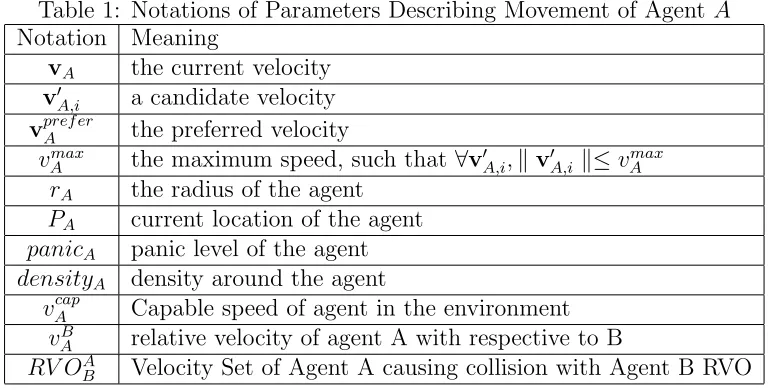
Notations used inthe following discussion are listed inTable 1.
Table 1: Notations of Parameters Describing Movement of AgentA
Notation Meaning
vA the current velocity
v′A,i a candidate velocity
vpref erA the preferred velocity
vmax
A the maximum speed, such that ∀v′A,i,∥v′A,i ∥≤vAmax
rA the radius of the agent
PA current location of the agent
panicA panic level of the agent
densityA density around the agent
vAcap Capable speed of agent in the environment
vB
A relative velocity of agent A with respective to B
RV OAB Velocity Set of Agent A causing collision with Agent B RVO
Collision
Avoidance
The process of collisionavoidancecould bedivided into four stages:
1. detecting whether there exists an on-coming potential collision with
other agent or obstacles; if there is no such collision, just choose the
preferred velocity and complete the collision avoidance process;
other-wise, go to step 2);
2. establishing the validate set for all candidate velocities based on
kine-matic and dynamic principles;
Destination Preferred Velocity Around Obstacles
Around Agents
Current Location
Environment Info
Detecting potential collisions?
Establish valid candidate velocity set
Y
Sampling from candidate velocity set
Evaluating sampled velocities
RVOfor collisions
with agents
VOfor collisions
with obstacles
Proposed method of parameter value assignment
N
Collision occurs? Collision response
Select velocity by the evaluation metric
Updating agent information and preparing coming into the next
simulation step
Y
N
Select preferred
velocity
Figure 1: Overview of the Motion Planning Model
4. evaluating each sampled velocity by the established evaluation method
and choosing the best one as the moving velocity for the current
sim-ulation time step.
In the following discussion, the shape of agent is assumed as a circle with
a specified centre point and radius. A collision of agent with another one is
defined as the two circles representing agents intersects. Similarly, an agent
collide with obstacle can be also described as the circle for the agent intersects
On-coming Collision Detection
The problem of collision detection can be converted into whether moving
circles intersect or not. Taking the detection of agent colliding with another
one as example, the collision detection can be executed as the following steps
(illustrated in Figure 2). The initial status (location,shape and location) of
the two agents are shown in Figure 2a. Based on these information, the
model detecta potential collisionas follows.
1. The circle of agent A can be overlaid on agent B, i.e., agent A can be
reduced to a point and the circle radius of circle come into rA+rB (as
illustrated in Figure 2b) ; the relative velocity ofA respective toB can
also be calculated by vA−vB. In this case, agentB can be considered
as a static object with the radius rA +rB, and agentA is a moving
point.
2. In order to detect the potential collision, it is then needed to figure out
the intersection point of the new circle of agent B and the ray for the
current location of agent A with the direction of the relative velocity
vA −vB. If there exists a intersection point, the distance between
A’s current location and the intersection point can be calculated. The
time-to-collision, which means how soon agentAwill collide with agent
B, can be also figured out (if there exists two intersection points, select
the smaller one as the time-to-collision). Otherwise, if there is no such
a point, the distance can be considered as infinite, and the
time-to-collision can also be considered as infinite, which means there is no
illustrated in Figure 2c.
vA vB
rA
rB
(a) Original Status
vA
rA
r+A
rB
vA
-vB
vB
(b) Relative Velocity
rA
rA+
rB
vA
-vB Dis tan ce be tw ee n A
& B
(c) Distance between A&B
Figure 2: Process of Calculating Time to collision
Validate Velocity Set and Velocity Sampling
Ifanagentdetectsanon-comingcollisionanddesirestoavoid thecollision, itwill
deviatefromitspreferredvelocityandchooseanotheronetoachieve it.Avalidate
velocity set should be first established to determine all possible candidate
velocities. The validate velocity set is built based on the agent’s kinematic and
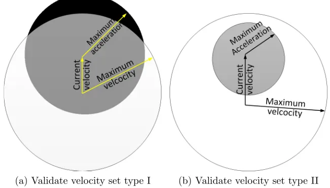
dynamicprinciples. Thevalidate velocitysetisbasedonagent’s maximumspeed
andmaximumacceleration.InFigure3thewhitecirclerepresentsallthevelocities
with the speed lessthanthe maximum speed. The black circleis the velocityset
forisallthe velocitiestowhichcanbeacceleratedordeceleratedfromthe current
selectedvelocity.Theintersection partof the twoset(presented ingraycolour)is
then the validate velocity set, inside which each velocitycan been considered as
candidatevelocity.However,itisnotpossibletoevaluateeveryvelocitybelongsto
velocities needs to be sampled from the set, which refers to the process of
velocitysampling.
(a) Validate velocity set type I (b) Validate velocity set type II
Figure 3: Validate Velocity Set Determination
The main idea of velocity sampling from the validate velocity set is to
2hoosetypicalvelocitytorepresentallthevelocitiesbelongedtotheset.Regarding
this, thesampling velocityshould beuniformly distributedinsidethe intersection
ofthetwocircles(i.e.,thevalidatevelocityset).Theshapeofthevalidatevelocity
set falls into two types: 1) the shape illustrated in Figure 3a, in which some
velocitysatisfiedthe acceleration requirementis outsidethe maximumspeed set;
and2)theshapeofvalidatesetiswhole velocitysetsatisfyingtherequirementsof
acceleration(showninFigure3b).
For both type of interaction part, a uniformly distributed function is built
by Equation 1).
where P(x,y) is a point inside the intersection part; x and y represents the
two velocity components along x and y coordinate, respectively; rspeed and
racc represents the maximum speed and value of acceleration holding by the
agent; centrespeed is the centre point of the velocity set for those satisfying
the maximum speed requirement; accordingly, centeracc is the centre point
of the velocity set for those satisfying the maximum value of acceleration
requirement. With a given number of velocity sampling and executing the
equation with the same number of time, the results (i.e., a serial of points),
uniformly distributed insidethe intersectionpart.
Velocity Evaluation
A velocity evaluation method is proposed in (van den Berg et al., 2008) to
evaluate whether the candidate velocity is proper for current situation:
penaltyA,B(v′i) = wi 1 tci(v′i)
+∥vprefA −v′i ∥, (2)
where v′i is a candidate velocity of agent A, tci(v′i) is the time to collision with
agent B by holding the current candidate velocity v′i, vApref is the preferred
velocity, and wi is the safety factor.
This formula indicates that a trade-off is made for the velocity selection
between maintaining current velocity to ignore the collision and deviating
from the preferred velocity to avoid the collision: the first item of the
for-mula (witci1(v′
i)) reflects how long the collision will occurs with the candidate
velocity, v′i; and the second part (∥vprefA −v′i ∥) is about how much the
for an agent, A, is subjected to the following process: 1) given a candidate
velocity, the penalty values for all its neighbors are calculated by Formula 2
and the minimum value is selected; 2) as a result, every candidate velocity
holds such a value; 3) the velocity, with the minimum penalty among all the
candidate velocities, is selected. This process can be formulated as
v= min
v′i∈CV minj∈N penaltyA,B(v
′
i), (3)
where CV is the set of all the candidate velocities of the agent i, and N is246
the set of allthe detected neighbors of the agent.
InordertoapplyFormula2toevaluatevelocity,thetime-to-collisionisneededto
befiguredout.InOn-comingCollisionDetectionsection,a methodismentioned
tocalculatetime-to-collisionfordetectingpotentialcollisions.Inthismethod,the
coreproblemistodeterminehowtocalculatetherelativevelocitybetweentwo
agentsoragentandobstacle.Actually,theexistingmethodsofVOandRVOare
proposedforcalculatingtherelativevelocity.VOandRVOaretwovelocitysetsin
whichanyvelocitywillgeneratecollision.Thesetwovelocitysetsholddifferent
assumptions:VO assumesthatonethinktheotherwillnotresponsetohis
collisionavoidance;onthecontrary,RVOassumesthat bothofthetwoagentswill
respondtotheother’smotionofcollisionavoidance andmakethesame
contributiontothecollisionavoidance.DetailsaboutVOandRVOcanbefound
in(vanden Bergetal.,2008)and(FioriniandShiller,1998)respectively.Inthe
followingdiscussionofcollisionavoidance,VO/RVO canbereferredtoeitherthe
be distinguished inthe context.
WhenRVOisapplied,itimpliesthattheagentscontributethesameeffortto
avoideachother1.Fromthis,itcanbedeterminedthatBshouldchoose v′
B =vB
− ∆vA(vBisthecurrentvelocityofagentB)asitsnewvelocity,ifAchooses v
′
A
asitsnewvelocity(∆vA =v′A− vA andvA =v′A+∆vA).Therelativevelocity
ofAwithrespecttoBthencanbecalculatedas:
vBA = v′A−v′B
= v′A−(vB−∆vA)
= v′A−(vB−(v′A−vA))
= 2v′A−vA−vB. (4)
Then,thetime-to-collisioncanbefiguredoutbyapplyingEquation4to calculate
therelativevelocitybetweentwoagents.
Similarly, we can also apply the formula to select velocity based on the
as-sumption of VO. The only difference is the calculation of the relative velocity
of A with respect to B, which can be get by the following equation.
vBA =v′A−vB. (5)
Analysis of Safety Factor
In order to apply Equation 2 to evaluate candidate velocities and obtain the
velocitywiththe minimumvalueof penalty,thevalue aswellasitsmeaning
of parameterwi shouldbedetermined,whichisnot mentionedclearly inthe
paper van den Berg etal. (2008). The discussion inthis sectioncan also be
appliedwhen using VO tocalculate the relative velocity.
Generally, a pedestrian will follow her/his preferred velocity until it
en-countersacollision;onceapotentialcollisionisdetected,thepedestrianmay
adjust the velocitywith a minimum deviation. Given all the parameters of
two agents, A and B, the velocity set of A, RV O,BAcan then be generated.
If vpref erA ̸∈ RV OAB, it implies that there will be no collision andvpref er will
be selected. When vpref erA ∈ RV OAB, a collision will be caused if selecting
the preferred velocity. In this case, another candidate velocity will replace
the preferred velocity. If a candidate velocity, v′A, satisfies the condition
B
v′A ̸∈ RVOA,thevalueofpenalty,calculatedbyFormula2,onlydependson
B
thevelocitydeviationduetotheinfinityvalueoftime-to-collision.Otherwise
(∀v′A ∈ RVOA),thevaluepenaltywillalsobecontributedbythenon-infinite
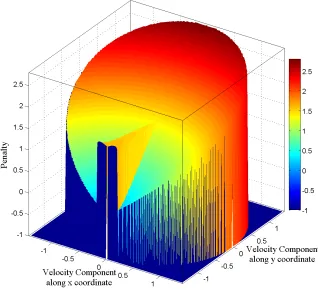
value of time-to-collision on the basis of the velocity deviation. As an
exam-ple, Figure 4 illustrates the penalties for all the candidate velocities of agent,
A, when itcome towardsthe other agent, B, with the followingconditions:
vA = (−1.4m/s,0),vB = (+1.4m/s,0),
vpref erA = (−1.4m/s,0),vpref erB = (−1.4m/s,0),
PA = (15m,0), PB = (0,0),
rA = rB = 2m,
vAmax = vmaxB = 1.4m/s,
If all the parameters are given, how much the penalty raised due to col- lision
is determined by the safety factor, wi. If wi = 0, the penalty only depends
onthe velocitydeviationfrom Formula2 and the agent will always choosethe
preferred velocity, which causes the agent not to consider the coming collision.
Withthe increaseof wi,the penalty will beraisedaccordingly.
Figure 4: An Example of Penalty Value Distribution
Actually, the velocity selection is the process to minimize the penalty,
which can be achieved at either the edge of RVO (avoiding the collision) or a
point inside RVO (ignoring the collision). If the preferred velocity does not
locate at the center of RVO, there exists a deviation, labeled as dv, between
the preferred velocity and the one inside the RVO and holding the minimum
the agents, we can assume dv ≃ 0. If the minimum penalty is achieved by
a velocity outside the RVO, it should locate at the edge of the RVO with
a minimum velocity deviation, which is labeled as vs. If the collision-free
motion is needed, the condition:
∥vApref er −vs ∥< wi
t1
+dv≃ wi
t2
(7)
must be satisfied, where t1 is the time to collision with the velocity achieving
the minimum penalty inside the RVO, and t2 is the time to collision with
the preferred velocity. Here the first item in the inequality is for the velocity
on the edge of RVO; the second item is for the velocity at a specified point
in RVO; and the last item is for the velocity along the preferred velocity.
Again, because the distance between them is much larger than the radii of
the agents, we can assume t1 ≃ t2, due to the low velocity of pedestrian.
Actually the angles among the three velocities are very small. Then we have,
wi > t2∗ ∥vpref erA −vs ∥, (8)
where t2∗ ∥ vApref er −vs ∥ denotes the threshold: if wi is larger than it, the
agentpreferstoavoid thecollision;otherwise, itwillmove alongitspreferred
directionand ignorethecollision. This canbeexplainedbythefactthat the
agentignoresthe comingcollisionwhen thedistancebetween thetwo agents is
far; and the agent avoids the collisiononce they get closer.
However, with a normal sensor range, such distance is much larger than
distance agents beginning to avoid each other and the safety factor. The
parameters of the two agents are set the same to those in Figure 4, with
the only exception of the 200m of the distance between them. The distance
can be very large,when wi >= 1.7 (24.67m). In case of this, the selection of
safety factor will be nonsense when the normal sensor range is much smaller
than the corresponding distance. The reason for this is that the distance
between the two agentsis much largerthan the radius of the agent.
0 1 2 3 3.4 4 5 6 7 8 9 10
0 20 40 60 80 100 120 140 160 180 200 Saftey Factor D ista n ce
distance beginning to avoid collision
indicator for minimum distance for collision avoidance indicator for distinct distance change for collision avoidance
Figure 5: Relationship between Safety Factor and Minimum Distance for
Collision Avoidance
Themeaningofthesafetyfactorwhenanagentmeetsseveralagents310differsfrom
that whenitencountersonlyone.Here, the agent,namelyi,still needstomake a
trade-off,but amongalltheotheragentsaround.Thisdependsonthevalueofthe
penalty with a safety factor. Consider two agents, j and k around, the agent i
needs to select a velocity which make a minimum penalty from Formula 2.
There exit two velocities, vj and vk, which achieve the minimum penalty for
agent j and k, respectively. Based on the previous analysis, we can claim that
both of the two velocities will make a collision-free motion for the
todeterminewhichoneissmaller.Forvelocityv1,wehavethepenaltypj=wi/tj+
dvj,wheretjisthetime tocollisionwithagentj,anddvjisthevelocitydeviation
between the preferred velocityand vj . Similar, for velocityv2, the corresponding
penaltyispk=wi/tk+dvk.Incaseofdvj<dvkand322tj>tk,pjshouldbesmaller
thanpk,whichmakesvjasthe selectedvelocity. However,ifthetwovelocitiesare
subjecttotheconditionsofdvj>dvkandtj>tk,thesafetyfactor,whichscalesthe
firstitembywitimes,makesan impactontheselectionofminimumpenalty.Let’s
considerthe following two extreme conditionsfor the two velocities: tj→ ∞ and
dvk=0,whichindicatesthatvjwillmakea
collision-freemotionwithagentj,vkisalongthedirectionofthepreferredvelocityofagent
i,and1/tk → 0.Remembervjwill makeacollision-freemotionwithagent
j,thenthemaximumofthevelocity
derivation is ∥vpref eri ∥. It is achieved when ∥vj∥= 0. In such conditions, we
need to compare which of the two items is smaller: wi/tk ordvj =∥vpref eri ∥.
The threshold of safety factor can be formulated as tk∗ ∥vpref eri ∥. The other
extreme assumption is that both i and k move towardseach other with the
speed ∥vpref eri ∥, and ∥vpref erk ∥ (∥vpref eri ∥ = ∥vpref erk ∥ ), with the distance
Dik, tk then can be calculated as Dik/2∗ ∥vpref erk ∥. Then the threshold of
the safety factor is Dik/2. Then the meaning of safety factor for navigation
agentaroundseveralothersnearbyis: ifthevalue ofsafetyfactor issetlargeran
half of the minimum distance to all its neighbors, the agent prefers to avoid
the instant collision; otherwise, it just ignore the collision and moves along
the direction ofits preferredvelocity. We name thisthreshold for safety factor
isthe strict one. Associatedwith the previousanalysis,the maximum distance
threshold for safety factor shouldbe halfof the sensorrange.
Selection of Safety Factor
From the analysis in last subsection, the safety factor, wi, represents how far an
agentbeginstoavoidthecollision.Thefollowingissueisabouthowto347selectthe
valueofwiindifferentscenarios.
The movement of a pedestrian in a crowd is constrained by the features of
the crowd. The fact is that the pedestrian’s speed is related to the pedestrian
density around her/him: if the density is high, the walking speed should be
slow; otherwise, the pedestrian can walk freely with a high speed. (Hughes,
2002) proposes a relationship between pedestrian’s walking speed and density,
formulated as follows:
f(ρ) =
A, ρ≤ρtrans
A(ρtrans/ρ)1/2, ρtrans < ρ≤ρcrit A(ρtransρcrit
ρmax−ρcrit)
1/2 (ρmax−ρ)1/2
ρ , ρcrit < ρ≤ρmax
(9)
whereρtrans,ρcrit, andρmaxhavetypicalvalues of0.8,2.8and5.0m−2, and349the
typicalvalueforAis1.4m/s.Adoptingthisformula,aspeedofanagent,350A,can
becalculatedwiththegivendensity,whichiscalledcapablespeed,
vcapA .
On the other hand, the pedestrian may hold her/his preferred speed,
∥ vpref erA ∥, which indicates how fast she/he desires to walk and related to
her/his panic level. Here we simply divided the panic level into three
veloci-ties, are set with the values of 1.4, 2.0, and 3.5m/s, respectively. The
max-imum acceleration is set to 1, 2, and 2.5m/s2 for the three types of agents.
This setting corresponds to the human step frequency reported in (Mazarakis
and Avaritsiotis, 2005), which varies from 0.9Hz to 3.5Hz, with a mean of
2Hz. Then, we set the safety factor, wi, is determined by the follows:
wi =collision dstandard v
cap
∥vpref erA ∥. (10)
weadoptthefieldofvisionproposedin(Feurtey,2000),whichiscomposedbya
sector,centeringatthepositionoftheagent,withtheangleof160oandradiusof
10m.Thencollisiondstandardissetto5m,whichisthehalfof sensorrange.
AssociatedwithFormula8,thattheagentwilleitheravoidor justignorethe
comingcollision can bedetermined.
TheconceptofRVOrequirestheassumptionthatbothoftheagentswillmakethe
samecontributionforthecollisionavoidance.Ifbothoftheagents detectthesame
comingcollision,RVOisappliedinFormula2.However,if oneofthemdoesnot
catchsightoftheotherone(e.g.onefollowingtheotherone),RVOshouldnotbe
applied.Ifthiscase,VOisappliedinFormula2fortheonedetectingthecollision.
Theawarenessoftheotheragentcan bedeterminedbycheckingwhetherthe
otheragentisinthevisionfieldof theagent.Incaseanagentencountersa
moving/staticobstacle,VOisalso appliedinFormula2togeneratethemotions
Collision Response
If a collision does occur during the simulation, collision response is neededfor
the agent. We assume that each agent is represented by a circle. The
collision between two agents can then be detected when the circles of the
two agents overlap. In this paper, a rule-based collision response model is
applied, which isproposed in our previous paperXiong et al.(2010).
Collisionscanbedistinguishedbythecollisiontypeandthespeedswith373which
thetwoagentscollide.Differenttypesofcollisioncancauseanagenttorespond
differently.Firstofall,acollisioncanbecategorizedintotwo types:sidecollision
andhead-oncollision.Anexampleofthetwotypesof collisions.Anhead-on
collisionforAgentAwithAgentBoccurswhen:1) thecirclesrepresentingAand
Boverlap;and2)theraystartingfromthecenterofthecirclerepresentingAand
alongthedirectionofA’svelocity, intersectsthecirclerepresentingB.Allthe
othercollisionsareconsideredassidecollision.Asidecollision,whichweassume
tobelesssevere,mayonlyslowdowntheinvolvedagentsslightly.Thehead-on
collision,onthe contrary,reflectsasignificantcollision,inwhichanagentmust
stopforawhilebeforeitcontinuesitsmovement.Secondly,theagent’scurrent
speediscategorizedintothreecategories,i.e.,lessthan1.7m/s,between1.7and
2.8m/s,andlargerthan2.8m/s.Therulesofthecollisionresponsemadebythe
agentaredefinedinTables2and3(wherevAandvBrepresentsthecurrentspeed
oftheAgentAandB,respectively),involvingthefollowingactions:
its current speed);
ii) the velocity direction will be turned away from the collision with an
angle φ(here φ=π/9);
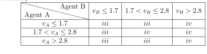
iii) the agent stops for the time of tstop (it is assumed that thetstop = 0.5s
for side collision and tstop = 2s for head-on collision); and
iv) the agent falls down, where the agent also needs time oftf all before it
continue to move (here tf all is set as 3s).
i + ii means the agent will execute the two responses simultaneously. Note,
for actions iii and iv a random positional deviation is applied to the agents to
avoid repeated collisions. While semi-random, this adjustment is performed
according to the resulting collision force between the two agents. This
ad-justment only aims to separate an agent colliding with another one, but not to
consider any on-coming collisions. As a result, the agent may continuously
re-collide with other agents around, which can further increase the overall
numberof collisions.
Table 2: Collision Response of Agent A Colliding with Agent B (Side Colli-sion)
XXXXX
XXXXXXX
Agent A
Agent B
vB ≤1.7 1.7< vB ≤2.8 vB >2.8
vA ≤1.7 i+ii iii iii
1.7< vA ≤2.8 i i+ii iii
Table 3: Collision Response of Agent A Colliding with Agent B (Head-on Collision)
XXXXX
XXXXXXX
Agent A
Agent B
vB ≤1.7 1.7< vB ≤2.8 vB >2.8
vA ≤1.7 iii iii iv
1.7< vA ≤2.8 iii iv iv
vA >2.8 iii iii iv
Case Study
Inthissection,theexperimentresultsareshowedtovalidatetheproposed motion
planning model.The experiments are dividedinto three parts: differentvalues of
safety factor for agent navigation, collision response for different collision type,
andaconcretescenarioforagentmovingaroundthesimulation environment.
Evaluation of Safety Factor
411
The first group of experiment is designed to examine the impact of the safety
factor on the collision avoidance when multiple agents are around. In the
experiment,alltheagentsintheexperiment,uniformlylocating atacircle, desire
toachievethe positionattheotherside ofthe circle.Thevalue of safetyfactor is
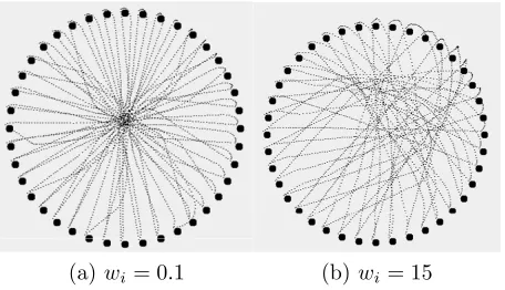
fixedsetto0.1and15respectively,andnocollisionresponseis considered.Figure
6 illustrates the simulation results of this scenario, where the solid circles
represent the initial positions of agents; dark dots represent the trajectoriesof
those movingagents.Each agentdesirestomove tothe otherside of thecircle in
the simulation environment. When the safety factor is set to 0.1, it is shown in
get very closedbefore they begin toavoid the coming collision; compared with
this, the agents begin to avoid the others with 15 for the safety factor, when
they are far away from each other, (shown in Figure 6b). This validates the
fact that: the agent prefers to avoid each other when safety factor is larger;
and they become sluggish and pretend not to detect the coming collision,
once the safety factor is smaller. Finally, they avoid the other agents around
until the distances among themdrop to athreshold.
(a)wi= 0.1 (b)wi= 15
Figure 6: Agents Changing Their Positions in Circle with Different Value of Safety Factor
Collision Response
Differenttypesofcollisionresponses,i.e.,sideandhead-oncollisionare
demonstratedinFigure7,where∆trepresentsthesimulationtimestepand isset
to0.5shere.Therearetwoagentsinvolvedinthecollisionresponseprocess.Both
agentsholdthespeedof1.4ms.
Forsidecollision(demonstratedinFigure7a),thetwoagentdropsits speedto
80%ofitsoriginalspeedandturnawayfromitsoriginaldirectionwithanangle
t
0
t
0
+
t
v
A
v
B
v
A
v
B
(a) side collision response
t
0t
0+
t
v
Av
Bv
A=(0,0)
v
B=(0,0)
t
0+4*
t
v
Av
B(b) head-on collision response
Figure 7: Response for Side and Head-on Collisions
recovery (speed of both agent less than 1.7ms), two agents involved in side
collisionisabletocontinuetheirmovementimmediatelyaftertheoccurrence of
side collision, only by adjusting their speed and moving direction. Detailed
positionand velocityinformation oftwo agents before and afterthe collision is
shown inTable 4.
Head-on collision, as mentioned Table 3, makes agents involved in the
collisionstopping/fallingandwaitingforcollisionresponseand recovery.
Af-ter collision occurs, the two agents are separated by collision force. Since
both agents hold speed less than 1.7ms, they need 2s stop time for
Table 4: Positions and Velocities of Agents in Process of Collision Recovery (Side Collision)
XXXXX
XXXXXXX
Notation
Time
t0 t0+ ∆t
vA (1.0,0) (0.94,−0.34)
vB (−1.0,0) (−0.94,0.34)
PA (10.0,10.0) (10.47,9,83)
PB (10.4,10.4) (9.93,10.57)
information of two agents before and afterthe collisionis shownin Table 5.
Table 5: Positions and Velocities of Agents in Process of Collision Recovery (Entire Collision)
XXXXX
XXXXXXX
Notation
Time
t0 t0+ ∆t t0+ 4∆t
vA (1.0,0) (0,0) (1,0,0)
vB (−1.0,0) (0,0) (−1.0,0)
PA (10.0,10.0) (9.3,9.3) (9.8,9.3)
PB (10.3,10.0) (11.0,10.7) (10.5,10.7)
Scenario with Different Panic Levels
The following experiments apply the proposed motion planning model into a
concrete scenario. There are two groups of agents in this scenario, including
three columns agents in each group. Initially, the two groups locate at left
and rightedge of theenvironment, with thedistanceof 16m. Then theagents in
both of the two groups begin to move towards each other to exchange their
positions between the two group to exchange their positions between the two
groups, which means the goal of each agent is 16m away from its original
position. For example, an agent locating at the point with the coordinate
(a)Simulation Time 0s (b)Simulation Time 4.0s
(c)Simulation Time 6.0s (d)Simulation Time 8.0s
(e)Simulation Time 12.0s (f)Simulation Time 19.0s
Two experiments are conducted for the scenario, differentiating in the
compositionofagentpaniclevelineachgroups.Agentsinthe first experiment are
allin normal paniclevel, with the preferred speedof 1.4m/s. Figure8 shows the
snapshotof the simulation process,where agentsare dotted withblack colorand
theassociatedshortlineindicatestheagent’svelocity,bothindirectionandspeed.
From the experiment result, it can be observed that the shape of agent columns
does not changemuch. For anagent with normal panic level,agent executes the
collisionavoidancemotionwhentheyarerelativelyfarawayfromeachother.This
makesthemotionofcollisionavoidancedeviateslightlyfromitspreferredvelocity.
This causes agents ineach group moves in order evenwhen they meet and come
across each other. On the contrary, agents composed with different panic level
behaves much differently for the second experiments. In this experiment, each
group agents are composed of three types of panic levels, coloured with black,
green and red for normal, hurry and emergence panic level, respectively (as
shown in Figure 9). Since agent emergence and hurry panic level can tolerate
the on coming collision with a shorter distance that the normal panic level
agent, agents can moves much closer until they conducts the motion of
collision avoidance. This makes collision occurs with ahigher probability, which
makes the agent to conduct the motion of collision response. Agent during the
process of collision response is represented as circle inFigure9.Additionally, it
can also be observed that the agents with emergence panic level holds the
(a)Simulation Time 0s (b)Simulation Time 2.0s
(c)Simulation Time 5.0s (d)Simulation Time 7.0s
(e)Simulation Time 10.0s (f)Simulation Time 22.0s
agent with normal panic level
agent with hurry panic level
agent with emergence level
Figure 9: Two Groups of Agents Exchanging Their Positions with Three
Performance Evaluation
Theperformanceevaluationfortheproposedmotionplanningmodelisbased
onthescenariousedinthepreviousSection. Twoexperimentsarecompared for
performance evaluation, foragents with normaland three typesof panic levels.
The movement for the scenario can be divided into three stages: 1)agents
start to move at the beginning of the simulation; 2) two groups of agentsget
closerandbegintoconductthemotionofcollisionavoidance; and3) after two
groups of agents come across each other, they continue their movementto
achieve the desireddestination.
ThesimulationresultisshowninFigure10,andthethreestagesofagent
movementisdifferentwiththesimulationcost.Atthefirststage,itcanbe
observedthatthesimulationcostisrelativelow.Whenitcomesintothe second
stage,itgoeshigherforbothexperiments.Thisisduetotheincrease ofthe
velocitysamplingnumber.Attheinitialstage,agentscanapplytheirpreferred
speedsincethetimetothepotentialcollisionislong.Noticedthat thevalid
velocitysetisintersectionpartofthemaximumvelocitysetand maximum
accelerationset.Astheon-takingspeeddecreases,theintersectionpartwillgoes
larger.Duetothesamplingresolutionkeepingthesameduring the simulation
process,largerintersectionpartmeansmorevelocitywillbesampled insidethe
validvelocityset.Thismakesthesimulationcostgrowsupinthe secondstage.In
stage3,thesimulationcostdropsagainbecause agentsisabletochoosethe
preferredvelocityasthemovingvelocity.Atthe endofstage3,thesimulation
0 2 4 6 8 10 12 14 16 18 20 0
5 10 15 20 25 30 35 40 45
Simulation Time (s)
Simulation
Cost
(ms)
normal panic level three panic levels
Figure 10: Performance of Motion Planning Model Compared with Two Scenarios
It can also be observed that the experiment with different panic levels holds a
highersimulationcostthantheonewithnormalagent.Thisisbecauseexperiment
withdifferentpaniclevelsmaycausemorecollisions.Agentsinvolvedincollisions
needs to conduct the motion of collision response, which takes extra simulation
costforthis.
Acknowledgement
The authors thank editors and anonymous referees for helpful comments of
this paper. This work was supported in part by National Natural Science
Foundation of China (grant No.61103145), and the Fundamental Research
No.CUG120409).
Conclusion
In this paper, an adaptive motion planning mechanism is proposed for crowd
simulation,includingmotionplanningandcollisionresponse.Motionplanningis
divided into two separately parts, collision avoidance and collision response.
When an agentdetectsanon-comingcollisionanddecidestoavoid it,itselectsa
velocity deviating from its preferred velocityfor collision avoidance. The model
allows agent to collide with other agents or obstacles in some special scenarios,
whichcausesthe executionoftherule-based collisionresponsemethod.From the
experiment results, it shows that the proposed motion mechanism can generate
differentmotions indynamic environments. The agent withdifferent paniclevels
maybehave differently.In the futurework, such differences shouldbeconsidered
for the collision avoidance, which makes the agent with lower panic level pays
more contributioninthe collisionavoidancethanthe one with higherpanic level
does.
References
Ahn, J., Gobron, S., Silvestre, Q., Ben Shitrit, H., Raca, M., Pettr´e, J.,
Thalmann, D., Fua, P., and Boulic, R. (2011). Long term real trajectory
reuse through region goal satisfaction. In Proceedings of the 4th
interna-tional conference on Motion in Games, MIG’11, pages 412–423, Berlin,
Ahn, J., Wang, N., Thalmann, D., and Boulic, R. (2012). Within-crowd
immersive evaluation of collision avoidance behaviors. In Proceedings of
the 11th ACM SIGGRAPH International Conference on Virtual-Reality
Continuum and its Applications in Industry, VRCAI ’12, pages 231–238,
New York, NY, USA. ACM.
Feurtey,F.(2000).Simulatingthecollisionavoidancebehaviorofpedestrians.
Master’s thesis, the Univ. of Tokyo.
Fiorini, P. andShiller, Z.(1998). Motion planning indynamicenvironments
using velocity obstacles. Int. Journal of Robotics Research, 17(7):23–33.
Fox,D., Burgard,W.,andThrun,S.(1997). Thedynamicwindowapproach
to collision avoidance.IEEE Robotics & Automation Magazine, 4(1):23–33.
Gayle, R., Sud, A., Lin, M., and Manocha, D. (2002). Reactive deforming
roadmaps: Motion planning of multiple robots in dynamic environments.
Int. Journal of Robotics Research, 21(3):233–255.
Hughes,R.(2002).Acontinuumtheoryfortheflowofpedestrians.
Trasnsportation research PartB, 36(6):507–535.
Jaillet, L. and Simeon, T. (2004). A prm-based motion planner for
dynamically changing environments. In in Proceedings of IEEE/RSJ Int.555
Conference on Intellegent Robots and Systems, pages 1606–1611.
Koh, W. L. and Zhou, S. (2007). An extensible collision avoidance model
IEEE International Symposium on Distributed Simulation and Real-Time
Applications, pages 7–14. IEEE Computer Society.
Lamarche, F. and Donikian, S. (2004). Crowd of virtual humans: a new
ap-proach for real time navigation in complex and structured environements.
Computer Graphics Forum, 23(3):509–518.
Li, Y. and Gupta, K. (2007). Motion planning of multiple agents in virtual
environments on parallel architectures. In Proceedings of IEEE
International Conference on Robotics and Automation, pages 1009–1014.
Mazarakis, G. P. and Avaritsiotis, J. N. (2005). A prototype sensor node for
footstep detection. In Wireless Sensor Networks, 2005. Proceedings of the
Second European Workshop on, pages415–418.
Nguyen, Q. H., McKenzie, F. D., and Petty, M. D. (2005). Crowd behavior
cognitive model architecture design. In Proceedings of the 2005 Behavior
Representation in Modeling and Simulation (BRIMS) Conference, pages
55–64, UniversalCity, CA.
Pelechano, N., Allbeck, J., and Badler, N. (2007). Controlling individual
agents in high-density crowd simulation. In ACM SIGGRAPH /
Euro-graphics Symposium on ComputerAnimation (SCA’07), pages 99–108.
Pelechano, N., O’Brien, K., Silverman, B., and Badler, N. (2005). Crowd
simulation incorporating agent psychological models, roles and
commu-nication. In Proceedings of the First International Workshop on Crowd
Shao, W. and Terzopoulos, D. (2005). Autonomous pedestrians. In
Proceed-ings of the 2005 ACM SIGGRAPH/Eurographics symposium on Computer
animation,pages 19–28.
Stephen, C. (2004). Flow tiles. In Proceedings of the 2004 ACM
SIG-GRAPH/Eurographics symposium on Computer Animation, pages 233–
242, San Diego, California, USA.
Sud, A., Andersen, E., Curtis, S. andLin, M., and Manocha, D. (2007).
Real-time path planning for virtual agents in dynamic environments. In
Proceedings of IEEE VirtualReality, pages 91–98.
Thalmann, D. and Musse, S.(2007). Crowd Simulation. Springer.
Treuille, A., Cooper, S., and Popovi´c, Z. (2006). Continuum crowds. In
Proceedings of ACM SIGGRAPH, pages 1160–1168.
van den Berg, J., Lin, M., and Manocha, D. (2008). Reciprocal velocity
obstacles for real-time multi-agent navigation. In Proceedings of IEEE
International conference on robotics and Automation, pages 1928–1935.
Xiong,M.,Lees, M.,Cai,W.,Zhou,S.,andLow,M.Y.-H.(2010).Analysisofan
efficient rule-based motion planning system for simulating human crowds. The