DEFLECTION OF CONCRETE SLABS
CURRENT PERFORMANCE & DESIGN DEFLECTION LIMITS
SHIVAN TOVI
A thesis submitted in partial fulfilment of the requirements of The University of West London
for degree of Doctor of Philosophy
This research programme was carried out in collaboration with the Concrete Centre
ii Declaration of Authorship
iii Abstract
Thesis title: Deflection of Concrete Slabs
Current Performance & Design Deflection Limits
Degree: Doctor of Philosophy Author: Shivan Tovi
Date: February 2017
Deflection is usually controlled by limiting the span/depth ratio. One aspect of this research is to document the deflection of a concrete slab in a large residential block. The other part of the research is to look at current design limits. Limits on deformation were set many decades ago, when the forms of construction, partitions, finishing, cladding and service were very different from what they are now. Part of that is to review the span-to-depth method of design.
Site investigation and testing theory through observation and data collection was the main deductive approach of this research. A quantitative method was used to calculate and determine the deflection on concrete slabs, the research is attempted to identify target companies and projects to participate in the research. The data indicate that the slab has not sagged significantly due to the back propping for 30 days. However, it does seem that the slab was sloping down from the corner by 6 mm diagonally across the 12m bay. A margin of deflection around 2mm occurred especially in the mid-span of the slab 12 x 7 m corner bay. The 2 mm deflection occurred at the beginning of the investigation after back propping reinforced concrete corner bay slab. The back propping applied after 7 days of pouring slab.
iv Table of Contents
Declaration of Authorship... ii
Abstract ... iii
Table of Contents ... iv
List of Figures ... ix
List of Tables ... xii
Acknowledgements ...xx
Dedication ... xxi
List of Publications Arising from this Thesis ... xxii
CHAPTER ONE: Introduction to Deflection on Slabs ... 23
1.2 General ... 27
1.3 Research Aims, Questions and Objectives ... 34
1.3.1 Aims ... 34
1.3.2 Research Questions ... 35
1.3.3 Objectives ... 35
1.4 Eurocode Group ... 35
1.4.1 Eurocode 2 ... 36
1.5 Eurocode 2 Deflection Design and Analysis ... 38
1.6 Factors Affecting Deflection ... 39
1.6.1 Creep ... 40
1.6.2 Tensile Strength ... 40
1.6.3 Elastic Modulus ... 41
1.6.4 Cracking ... 42
1.6.5 Shrinkage Curvature ... 43
1.6.6 Loading Succession ... 43
1.7 Deflection Checking Methods ... 44
1.8 Deflection Calculation Methods ... 46
1.8.1 Rigorous Method ... 46
1.8.2 Simplified Method ... 46
1.9 Research Structure ... 47
1.10 Research Contribution ... 48
CHAPTER TWO: Literature Review of Deflection of Slabs ... 51
2.1 Deflection of Slabs ... 51
v
2.1.2 Long Duration Deflections ... 54
2.2 Maximum Deflection ... 55
2.3 Cracking Impact on Concrete Slabs ... 58
2.4 Deflection Calculation ... 60
2.5 Design Code Limitations for Deflection ... 64
2.6 Compendium ... 66
2.7 Shortening of Columns ... 67
2.8 Precamber ... 69
2.9 Accuracy of Eurocode 2 ... 70
2.10 Flat Slabs ... 70
2.11 Cladding Allowances ... 71
2.12 Combined Reaction ... 72
2.13 Strain and Stress Relationships ... 75
2.14 Concrete ... 75
2.15 Steel ... 77
2.16 Shrinkage of Concrete and Hydration ... 78
2.16.1 Restrain Shrinkage and Stress Calculation ... 80
2.16.2 Fully Restrained Shrinkage and Stress Calculation ... 82
2.16.3 Elastic Modulus of Concrete ... 83
2.17 Thermal Behaviour of Concrete and Steel ... 86
2.18 Creep ... 87
2.19 Concrete Specification ... 88
2.20 Steel Specification ... 91
2.21 Structural Analysis at the Limit State ... 93
2.21.1 Permanent loads ... 95
2.21.2 Variable Loads ... 96
2.22 Summary ... 97
CHAPTER THREE: Methodology and Site Investigation ... 100
3.1 Introduction... 100
3.2 Various Methods for Measuring Deflection ... 101
3.2.1 Precise Levelling ... 105
3.2.2 Hydrostatic Cells Levelling (HCL) Method ... 112
3.2.3 Shape Accel Array (SAA) Method ... 129
vi
3.3 Planned Sequence of Tasks ... 131
3.3.1 Authorisation ... 132
3.3.2 Quality Requirements ... 132
3.3.3 Materials ... 133
3.2.4 Tools ... 133
3.3.5 Plant ... 134
3.4 HLC’s Calibration Certificate ... 134
3.5 Striking of Slabs Calculation, Elephant & Castle MP1 – Block (H10C) ... 135
3.6 Summary ... 138
CHAPTER FOUR: Deformation of Multi-Storey Flat Slabs, a Finite Elements Analysis and Precise Levelling ... 139
4.1 Introduction... 139
4.2 Bentley: Structural Design Analysis Results ... 142
4.2.1 Detailing Rules ... 143
4.2.3 Materials ... 145
4.2.4 Finite Element Standard Plan ... 148
4.2.5 Long-term Deflection ... 150
4.3 ETABS: Structural Design Analysis Results ... 150
4.3.1 Computational Analysis ... 151
4.4 Precise Levelling ... 155
4.5 Summary ... 158
CHAPTER FIVE: Evaluation of Column Shortening in mid-rise Concrete Structures . 160 5.1 Introduction... 160
5.2 Review of Column Shortening Developments ... 162
5.3 Column Shortening Prediction ... 168
5.3.1 Column Shortening... 168
5.3.2 12-Storey Building Description ... 168
5.3.3 24-Storey Building Description ... 170
5.4 TCC55 and TCC55X Results and Discussion ... 173
5.4.1 Investigation of the Effects of Environmental Factors on Column Shortening, Ambient Temperature ... 173
5.4.2 Investigation of the Effects of Environmental Factors on Column Shortening, Relative Humidity ... 175
vii 5.4.4 Investigation of the Effects of the Mineralogy of the Aggregate on Column
Shortening ... 182
5.5 Summary ... 185
5.6 Recommendation ... 186
CHAPTER SIX: Analysis of Results and Discussion ... 187
6.1 Introduction... 187
6.2 Outline Description of Building and Structural Form ... 189
6.3 Construction Tolerance Specifications – Concrete ... 192
6.4 Discussion of Construction Tolerances ... 192
6.4.1 First Level (Highest Level) – Overall Tolerance of the Structure ... 192
6.4.2 Second level – Positional Tolerance of All Parts of the Structure ... 193
6.4.3 Third level – Dimensional Tolerance of The Individual Elements ... 193
6.4.4 Fourth level – Position Tolerance ... 194
6.5 Description of Movements ... 194
6.5.1 Dead Loads (Permanent)... 194
6.5.2 Imposed Loads (Live)... 195
6.5.3 Foundation Movement ... 196
6.5.4 Concrete - Long Term Concrete Effects (Shrinkage, Creep and Cracking) . 197 6.6 Pre-Cambering and Pre-setting ... 199
6.7 Construction Programme ... 199
6.8 Accumulation of Movement and Tolerances ... 200
6.8.1 Accumulation of Tolerances ... 200
6.8.2 Accumulation of Movements ... 201
6.8.3 Combination of Movement and Tolerances ... 201
6.9 Details of Structural Movement Limits ... 203
6.9.1 Vertical Deflection - Floor under Vertical Imposed and Dead Loading ... 203
6.9.2 Vertical Foundation Settlement ... 205
6.9.3 Axial Shortening of Concrete Cores Walls and Columns ... 205
6.9.4 Horizontal Deflection – Movement of the Structure under Gravity Loading 207 6.9.5 Movement of the Structure Subject to Thermal Actions ... 207
6.10 Allowances Required due to Structural Movement and Tolerance ... 208
6.10.1 Slab Movement and Tolerance ... 208
6.10.2 Vertical Movements Relevant to External Cladding ... 210
viii
6.12 Structural Frame Construction Tolerance ... 214
6.12.1 Overall Structure ... 214
6.13 Elements – Columns and Walls ... 216
6.14 Elements – Beams and Slabs ... 219
6.15 Section Elements ... 222
6.16 Position of Reinforcement within Elements... 224
6.17 Surface Straightness ... 226
6.17.1 Flatness ... 226
6.17.2 Edge Straightness ... 227
6.18 Discussion of Allowable Tolerances ... 228
6.9 Summary ... 235
CHAPTER SEVEN: Discussion and Conclusions ... 237
7.1 Aims of the Study ... 237
7.2 Deflection Limits ... 237
7.3 Methods of Controlling Deflection and Achievements ... 238
7.4 Contributions of the Study... 238
7.5 Limitations... 239
7.6 Standard Code of Design ... 240
7.7 Monitoring Slab Deflection ... 241
7.8 Lessons Learnt ... 242
7.9 Future Work and Recommendations ... 242
7.10 Conclusions ... 243
References ... 250
List of Appendixes ... 265
Appendix A ... 265
Appendix B ... 273
Appendix C ... 274
Appendix D ... 300
Appendix E... 301
Appendix F ... 308
Appendix G ... 309
Appendix H ... 310
ix List of Figures
Figure 1.1 Typical Floor Layouts... 41
Figure 2.1 Slab Precambering ... 69
Figure 2.2 Simulated Flat Slab Satisfied Criteria ... 71
Figure 2.3 Concrete and Steel in Composite Action ... 74
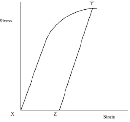
Figure 2.4 Stress and Strain Curve for Concrete in Compression ... 75
Figure 2.5 Stress and Strain (High Yield Steel) ... 77
Figure 2.6 Strain Hardening ... 78
Figure 2.7 Shrinkage Strain ... 81
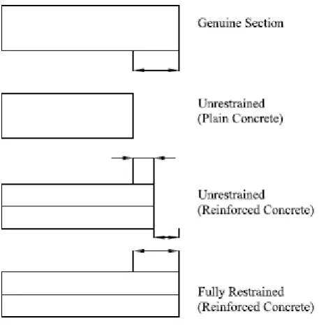
Figure 2.8 Cracking and Shrinkage Forces ... 83
Figure 2.9 Concrete Moduli of Elasticity ... 86
Figure 2.10 Typical Concrete Deformation by Time ... 87
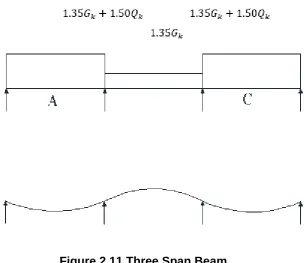
Figure 2.11 Three Span Beam ... 96
Figure 3.1 Precise Levelling Deflection of 2mm of on Selected Bay, refer to Figure 5.11 for more details ... 107
Figure 3.2 Levelling Instrument ... 109
Figure 3.3 Level Observing Deflection on Slab ... 111
Figure 3.4 Hydrostatic Cells Levelling System Connected ... 113
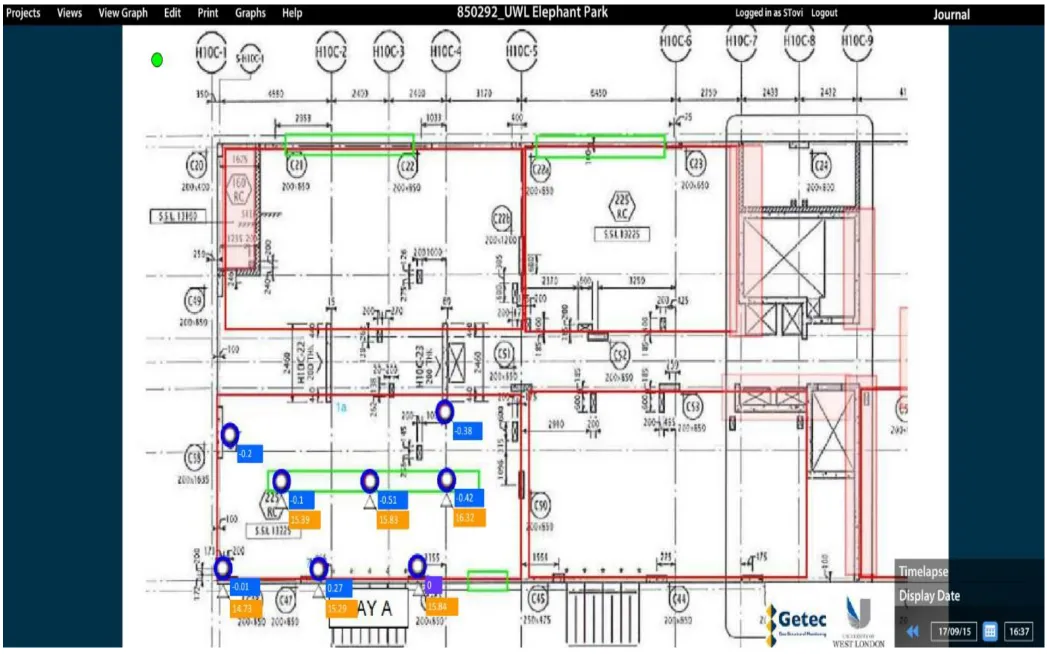
Figure 3.5 Hydrostatic Cell Levelling Location ... 114
Figure 3.6 Hydraulic Cell Level date box ... 115
Figure 3.7 Hydraulic Cell Level Network Connection ... 116
Figure 3.8 Hydraulic Cell Level water pressure reservoir ... 117
Figure 3.9 Hydrostatic Cells Levelling Connected to Data Box ... 118
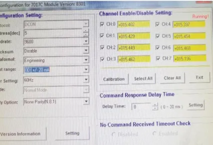
Figure 3.10 Hydrostatic Cells Levelling Monitoring Software ... 121
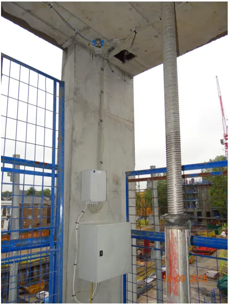
Figure 3.11 HCL System in Action Observing Deflection and Transferring Data ... 123
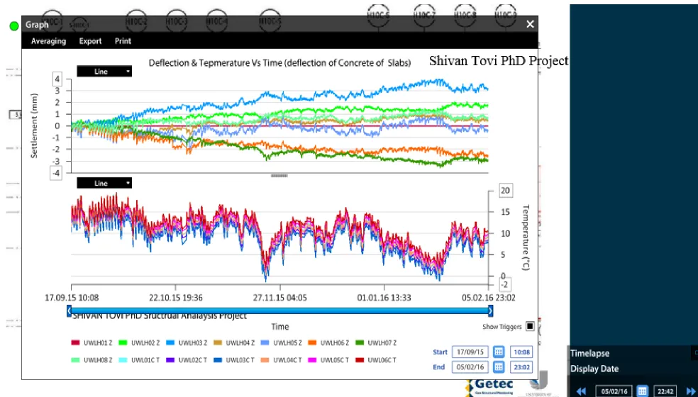
Figure 3.12 Deflection & Temperature Vs Time ... 124
Figure 3.13 Location of Site Investigation, Elephant & Castle - London ... 126
Figure 3.14 HCL Attached to the Underside of the Concrete Slab ... 128
Figure 3.15 Shape Accel Array (SAA) (Getec 2016) ... 129
Figure 3.16 (SAA) – Intrados Profile (Getec 2016) ... 130
Figure 3.17 Practicality of Shape Accel Array (SAA) (Getec 2016) ... 130
Figure 3.18 Optical Fibre Interferometer (Tayag et al 2003) ... 131
Figure 3.19 Loading Plan, Block (H10C), Refer to (Figure 5.2 and 5.3) for details ... 137
Figure 3.20 Calculation Sheet no.1 ... 310
Figure 3.21 Calculation Sheet no.2 ... 312
Figure 3.22 Calculation Sheet no.2 ... 314
Figure 3.23 Calculation Sheet no.4 ... 316
Figure 3.24 Calculation Sheet no.5 ... 318
Figure 3.25 Calculation Sheet no.6 ... 320
Figure 3.26 Calculation Sheet no.7 ... 322
Figure 3.27 Calculation Sheet no.8 ... 324
x
Figure 3.29 Calculation Sheet no.10 ... 328
Figure 3.30 Calculation Sheet no.11 ... 330
Figure 3.31 Calculation Sheet no.12 ... 332
Figure 4.1 Principle of Operation ... 334
Figure 4.2 Typical Cell Installation ... 336
Figure 4.3 Deflection of Reinforced Concrete Slab, Site Investigation ... 338
Figure 4.4 Deflection and Temperature Vs Time (Deflection of Concrete Slab) ... 339
Figure 5.1 Custom Span Detailing Rules ... 144
Figure 5.2 Loading Regions Colour and Number Coded [dashed rectangular] ... 146
Figure 5.3 Loading Regions Colour and Number Coded ... 147
Figure 5.4 Finite Element Standard Plan Block H10C, 3rd Floor Elephant and Castle - London ... 149
Figure 5.5 Long-term Deflection Plan due to Sustained Load ... 150
Figure 5.6 3D Grade Lines and Top View of Block (H10C) ... 151
Figure 5.7 3D and Top View of Block (H10C) ... 152
Figure 5.8 Point 36 on Third Floor Slab ... 153
Figure 5.9 Point 91 on Third Floor Slab ... 154
Figure 5.10 Point 89 on Third Floor Slab... 155
Figure 5.11 Precise Levelling Deflection of 2mm of on Selected Bay ... 157
Figure 6.1 Torsional Effect of Differential Column Shortening (reproduced from SlideShare, 2016) ... 163
Figure 6.2 Outrigger System ... 167
Figure 6.3 12-Storey Building Frame ... 170
Figure 6.4 24-Storey Building Frame ... 172
Figure 6.5 Ambient Temperature Simulation Results for 12-Storey Building Structure, Rotimi et al (in press), See Table 6.1 ... 173
Figure 6.6 Ambient Temperature Simulation Results for 24-Storey Building Structure, Rotimi et al (in press), See Table 6.2 ... 174
Figure 6.7 Relative Humidity Simulation Result for 12-Storey Building Structure, Rotimi et al (in press), See Table 6.1 ... 176
Figure 6.8 Relative Humidity Simulation Results for 24-Storey Building Structure, Rotimi et al (in press), See Table 6.2 ... 177
Figure 6.9 Slow, Normal and Rapid Hardening Cement Results for 12-Storey Building Structure, Rotimi et al (in press), See Table 6.1 ... 179
Figure 6.10 Slow, Normal and Rapid Hardening Cement Results for 24-Storey Building Structure, Rotimi et al (in press), See Table 6.2 ... 180
Figure 6.11 Aggregate Type Results at 5° C, 50% RH, and Normal Hardening Cement for the 24-Storey Building ... 182
Figure 6.12 Aggregate Type Results at 30°C, 50% RH, and Normal Hardening Cement) for the 24-Storey Building ... 183
Figure 7.1 MP1 Site (Master Plan 1 – Elephant & Castle – London) ... 190
xi
Figure 7.3 Movements and Tolerances Timeline ... 202
Figure 7.4 Breakdown of Slab Deflections ... 210
Figure 7.5 Edge Slab Deflection between Adjacent Floors (Robert Bird Group) ... 211
Figure 7.6 Ground Floor - Slab Edge Condition, (Robert Bird Group) ... 212
Figure 7.7 Brickwork Façade Supporting at the Concrete Slab Edge ... 213
Figure 7.8 Inclination of Floor edge, Column and Walls ... 215
Figure 7.9 Design Level at the Reference Level ... 215
Figure 7.10 Columns and Walls, Position on Plan ... 216
Figure 7.11 Vertically by Storey of the Structure ... 217
Figure 7.12 Offset between Floors ... 217
Figure 7.13 Curvature between Adjacent Floors ... 218
Figure 7.14 Curvature between Adjacent Floors, Side View ... 218
Figure 7.15 Distance between Adjacent Columns and Walls ... 219
Figure 7.16 Location of Beam to Column Connection ... 219
Figure 7.17 Position of Bearing Axis of Support ... 220
Figure 7.18 Straightness of Beams ... 220
Figure 7.19 Distance between Adjacent Beams ... 221
Figure 7.20 Inclination of Beams or Slab... 221
Figure 7.21 Level of Adjacent Beams ... 222
Figure 7.22 Position of Slab Edge ... 222
Figure 7.23 Cross-Section Beam, Colum and otheres Dimension of Elements ... 223
Figure 7.24 Cross-Section Slab, Beam and others Dimension of Elements ... 223
Figure 7.25 Cross-Sectional of Cover Dimension of Elements ... 224
Figure 7.26 Length of Reinforcement Lap Joints ... 225
Figure 7.27 Location of Reinforcement and Ducts in Pre-stressed Elements ... 225
Figure 7.28 Flatness ... 226
xii List of Tables
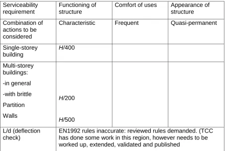
Table 2.1 Recommends Traditional Limiting Design values of Horizontal Deformations as
Function of High 𝐻 of Structure or High 𝐻1 Building ... 66
Table 2.2 Material property comparison between steel and concrete ... 72
Table 2.3 Elastic modulus of usual weight gravel concrete (short duration, 28 days) ... 84
Table 2.4 Concrete Strength Classes (Eurocode 2 2008) ... 89
Table 2.5 Steel Reinforcement Strength ... 91
Table 2.6 Traditional Limiting Design values of Horizontal Deformations as a Function of High 𝐻 of Structure or High 𝐻1 Building ... 99
Table 3.1 Comparison of Various Methods for Measuring Deflection on Slabs ... 104
Table 3.2 Planned Sequence of Tasks ... 131
Table 4.1 Technical Data ... 333
Table 4.2 Technical Data ... 339
Table 5.1 Bentley Design Rules (3rd Floor Elephant and Castel – London) Construction Site Block H10C ... 143
Table 5.2 Concrete Mix (3rd Floor Elephant and Castel Construction Site Block H10C) ... 145
Table 5.3 Load History Details ... 148
Table 5.4 ETABS Design Rules (3rd Floor Elephant and Castel – London) Construction Site Block H10C ... 151
Table 6.1 Geometry and Loading Sequence of the 12-Storey Building ... 169
Table 6.2 Geometry and Loading Sequence of the 24-Storey Building ... 171
Table 6.3 Results Summary for the Effect of Ambient Temperature on Column Shortening ... 175
Table 6.4 Results Summary for the Effect of Relative Humidity on Column Shortening ... 178
Table 6.5 Results Summary for the Effects of Cement Type on Column Shortening ... 181
Table 6.6 Results Summary for the Effect of Aggregate Type on Column Shortening ... 184
Table 7.1 Slab Deflection Criteria – Internal Conditions ... 204
Table 7.2 Slab Deflection Criteria – Slab edge Conditions ... 204
Table 7.3 Horizontal Movement Criteria, based on (Eurocode 2 2008) ... 206
Table 7.4 Building Temperature Variation ... 208
Table 7.5 Breakdown of Vertical Slab Movement & Tolerance... 209
xiii List of Acronyms / Abbreviations
Notation is commonly in accordance with Eurocode 2 and the principal List of Acronyms and Abbreviations are presented below. The common system of subscripts such that the first subscript refers to the material, such as (c - concrete and s - steel), and the second subscript refers to the form of stress, such as (c – compression and t - tension).
𝐸 modulus of elasticity
𝐹 load (action)
𝐺 permanent load
𝐼 second moment of area
𝐾 prestress loss factor
𝑀 moment (bending moment)
𝑁 axial load
𝑄 variable load
𝑇 torsional moment
𝑉 stress force
𝑎 deflection
𝑏 breadth (width)
xiv
𝑑′ depth to compression reinforcement
𝑒 eccentricity
ℎ overall depth of section in plan of bending
𝑖 radius of gyration
𝑘 coefficient
𝑙 length (span)
𝑛 ultimate load per unite area
1/𝑟 curvature of a beam
𝑠 spacing od shear reinforcement (depth of stress section)
𝑡 thickness
𝑢 punching shear perimeter
𝑥 neutral axis depth
𝑧 lever arm
𝐴𝑐 concrete cross-section area
𝐴𝑃 cross-section area of prestressing tendons
𝐴𝑠 cross-section area of tension reinforcement
𝐴𝑠′ cross-section area of compression reinforcement
xv
𝐴𝑠,𝑝𝑟𝑜𝑣 cross-section area of tension reinforcement provided at ultimate limit state
𝐴𝑠𝑤 cross-section area of shear reinforcement in the form of links (bent-up bars)
𝐸𝑐𝑚 secant modulus of elasticity of concrete
𝐸𝑠 modulus of elasticity of reinforcing (prestressing steel)
𝐺𝑘 characteristic permanent load
𝐼𝑐 second moment of area of concrete
𝑀𝑏𝑎𝑙 moment on a column corresponding to the balanced condition
𝑀𝐸𝑑 design value of moment
𝑀𝑢 ultimate moment of resistance
𝑁𝑏𝑎𝑙 axial load on a column corresponding to the balanced condition
𝑁𝐸𝑑 design value of axial force
𝑃0 initial prestress force
𝑄𝑘 characteristic variable load
𝑇𝐸𝑑 design value of torsional moment
𝑉𝐸𝑑 design value of shear force
𝑊𝑘 characteristic wind load
𝑏𝑤 minimum width of section
xvi
𝑓𝑐𝑚 mean cylinder strength of concrete
𝑓𝑐𝑡𝑚 mean tensile strength of concrete
𝑓𝑝𝑘 characteristic yield strength of prestressing steel
𝑓𝑦𝑘 characteristic yield strength of reinforcement
𝑔𝑘 characteristic permanent load per unit area
𝑘1 average compressive stress in the concrete for a rectangular parabolic stress section
𝑘2 a factor that relates the depth to the centroid of the rectangular parabolic stress section and the depth to the neutral axial
𝑙𝑎 lever arm factor = z/d
𝑙0 effective height of column (wall)
𝑞𝑘 characteristic variable load per unit area
𝑎 coefficient of thermal expansion
𝑎𝑐 modular ratio
𝜓 action combination factor
𝛾𝑐 partial safety factor for concrete strength
𝛾𝑓 partial safety factor for load (action), F
𝛾𝐺 partial safety factor for permanent loads, G
𝛾𝑄 partial safety factor for variable loads, Q
xvii
𝛿 moment redistribution factor
𝜀 strain
𝜎 stress
∅ bar diameter
𝐴𝑎 area of a structural steel section
𝐴𝑣 shear area of a structural steel section
𝑏 width of the steel flange
𝑏𝑒𝑓𝑓 effective width of the concrete flange
𝑑 clear depth of steel web (diameter of the shank of the shear stud
𝐸𝑎 modulus of elasticity of steel
𝐸𝑐,𝑒𝑓𝑓 effective modulus of elasticity of concrete
𝐸𝑐𝑚 secant modulus of elasticity of concrete
𝑓𝑐𝑚 mean value of the axial tensile strength of concrete
𝑓𝑦 nominal value of the yield strength of the structural steel
𝑓𝑢 specified ultimate tensile strength
ℎ overall depth (thickness)
ℎ1 depth of structural steel section
ℎ𝑓 thickness of the concrete flange
xviii
ℎ𝑠𝑐 overall nominal height of a shear stud connector
𝐼𝑎 second moment of area of the structural steel section
𝐼𝑡𝑟𝑎𝑛𝑠𝑓 second moment of area of the transformed concrete area and the structural steel area
𝑘1 reduction factor for resistance of headed stud with profiled steel sheeting parallel with the beam
𝑘𝑡 reduction factor for resistance of headed stud with profiled steel sheeting transverse with the beam
𝐿 length (span)
𝑀𝑐 moment of resistance of the composite section
𝑛 modular ratio (number of shear connections)
𝑛𝑓 number of shear connection for full shear connection
𝑃𝑅𝑑 design value of the shear resistance of a single connector
𝑅𝑐𝑓 resistance of the concrete flange
𝑅𝑐𝑥 resistance of the concrete above the neutral axis
𝑅𝑠 resistance of the steel section
𝑅𝑠𝑓 resistance of the steel flange
𝑅𝑠𝑥 resistance of the steel flange above the neutral axis
𝑅𝑣 resistance of the clear web depth
xix
𝑅𝑤𝑥 resistance of the web above the neutral axis
𝑡𝑓 thickness og the steel flange
𝑡𝑤 thickness of the steel web
𝑊𝑝𝑙,𝑦 plastic section modulus of the a steel structural section
𝛿 deflection at mid span
𝛾 factor of safety
𝑣𝐸𝑑 longitudinal shear stress in the concrete flange
xx Acknowledgements
Above all, prima facia, I am grateful to ALLAH ( ىلاعتو هناحبس
الله
) for all things I have the strength through him who gives me power, for the good health and wellbeing that were necessary to complete this PhD.Firstly, I would like to express my sincere gratitude to my advisor Charles Goodchild
Principal Structural Engineer from MPA The Concrete Centre for the continuous support of my PhD study and related research, for his patience, motivation, and immense knowledge. His guidance helped me in all the time of research and writing of this thesis. I could not have imagined having a better advisor and mentor for my PhD study.
Besides my advisor, I would like to thank Dr. Ali B-Jahromi, for his insightful comments and encouragement, but also for the hard question which incented me to widen my research from various perspectives.
My sincere thanks also goes to Lendlease and Morrisroe who provided me an opportunity to join their team as intern, and who gave access to the construction site. Without they precious support it would not be possible to conduct this research. A special thanks to my family. Words cannot express how grateful I am to my mother and father for all of the sacrifices that you’ve made on my behalf. Your prayer for me was what sustained me thus far.
xxi Dedication
To my parents for teaching me the purpose of life,
xxii List of Publications Arising from this Thesis
The following publications have been produced and presented in advance of the thesis, in which attached as an Appendixes of this thesis.
1. Tovi, S., Goodchild, C., Jahromi, B. A. and Sofroniou, A. (2016) A review of the span-to-depth ratio methods of design. Proceedings of the fib Symposium, 21 – 23 November 2016, Cape Town, South Africa.
2. Tovi, S., Goodchild, C. and Jahromi, B. A. (2017) Deformation of Multi-Storey
Flat Slabs, a Site Investigation. Daejeon: Techno Press.
3. Tovi, S., Goodchild, C. and Jahromi, B. A. (in press) Deformation of Multi-Storey
Flat Slabs, a Finite Elements Analysis and Precise Levelling. Daejeon: Techno
Press.
4. Jahromi, A, B., Rotimi, A., Tovi, S., Goodchild, C. and Rizzuto, J. (2017)
Evaluation of the influence of creep and shrinkage determinants on column
23 CHAPTER ONE: Introduction to Deflection on Slabs
1.1 Background of Span-to-Depth Ratio Methods of Concrete Slab Design Concrete flat slab structures are economical and the most popular form of concrete used in multi-storey structures. Deflection of slabs is a principal criterion in design, it governs thickness, which in turn has a significant economic impact. Deflection is usually controlled by limiting span/depth ratio. This paper reviews the history of the span-to-depth method of design.
Span/depth ratios are based on knowledge of deflection and currently, advances have been made in the calculation of deflection. Yet, the actual performance of restrained concrete slabs in the field remains largely unknown. Models have only rarely been calibrated against actual construction projects. This study aims to document the deflection of a concrete slab in a large residential block. The intention is to note any serviceability issues and to compare design models and assumptions with reality (Tovi et al 2016).
Limits on deformation were set many decades ago, when the forms of construction, partitions, finishes, cladding and service were very different from what they are now. It is possible, therefore, that the current limits are too conservative. In order to justify change, and enable more sustainable and economic designs, knowledge of the background to current limits and of current performance is needed. Part of that is to review the span-to-depth method of design.
24 The lower slabs in the supporting assembly is extremely loaded if reinforced concrete slabs do not carry their own weight before the reinforced slab above is cast. If the recently cast slab carries its own weight after loading, the construction load is given by:
𝑊𝑝𝑒𝑎𝑘 = 𝑊𝑠𝑒𝑙𝑓+ 𝐶(𝑊𝑠𝑒𝑙𝑓+ 𝑊𝑐𝑜𝑛) (Eq. 1.1)
Where 𝐶 is a carry through factor of at least 1/(number of supporting levels) and 𝑊𝑐𝑜𝑛 is a construction action (load) comprising formwork, which is usually close to 0.75 kN/m2. Beeby’s investigation states that, when backprops are installed, it is acceptable
in the absence of detailed calculation to take the 𝐶 value as 0.7 in Equation (1.1), if there is only one level of backprops, and as 0.65 if there are more than one level of backprops. Backprops are normally preloaded through installation rather than being installed, as at Cardington study case.
Vollum (2003) calculated significant preloads in the backprops at St George Wharf, as a uniformly distributed load of approximately1 𝑘𝑁/𝑚2. Preloading is useful because it induces an additional distribution of construction load between the supporting concrete slabs than calculated at Cardington.
Parametric studies have shown that it is acceptable to consider the peak construction load 𝑊𝑠𝑒𝑙𝑓 as 0.04ℎ 𝑘𝑁/𝑚2, where ℎ is the slab thickness in mm, in deflection calculations for slabs up to 500 mm thick where two levels of backprops are used and the backprops are preloaded throughout the installation, as Vollum (2003) demonstrates at St George Wharf.
Construction loads from casting concrete slabs above can only be ignored if:
25
Adequate backprops are provided to divert the self-weight of the recently cast slab to the ground
Caution should be applied in ignoring construction loads since calculations of prop forces at Cardington, as Hossain (2002) declares, and at St George Wharf, as in Vollum (2003), suggest that slabs can experience considerable construction loads from casting concrete slabs above them, even if the backprops continue to the ground, owing to the combined influence of prop shortening and floor settlement.
Beeby (1971) states that at an early stage in the development of the proposed new code of practice for the structural use of reinforced concrete members, the methods considered in British Standards Institution (1965) to control deflections were not fully satisfactory and would be even less satisfactory when the higher levels of reinforced steel stress allowed by the new code were used. It was agreed, however, that the simple technique of controlling deflections provided by span/depth ratios is essential for common use rather than insisting on the calculation of deflections in all circumstances.
Eurocode 2 (2008) calculates the mean curvature in cracked concrete members by interpolating between the curvatures in uncracked and cracked sections as:
Ψ𝑚 = 𝜉Ψ2 + (1 − 𝜉)Ψ1 (Eq. 1.2)
Where
𝜉 = 1 − 𝛽(𝑀𝑟/𝑀)2 (Eq. 1.3)
Ψ1and Ψ2are the curvatures in uncracked and cracked members, including shrinkage, while 𝑀𝑟 is the cracking moment when the moment 𝑀 is applied. The coefficient 𝛽
26 cracking when the slab is subjected to a sustained load. Eurocode 2 (2008) declares that coefficient 𝛽 should be considered as 1 for short term loading and 0.5 for long term loading, but it does not define the variation in the coefficient 𝛽 with time, although Vollum (2002) suggested 0.7 for construction loading.
Vollum (2002) also offered back analysis of the slab deflection date from laboratory and field investigation, and states that Equation (1.3) obtains good estimates of curvature and then deflection, if the material properties and loading are known. Difficulties appear in practice, however, since neither the material properties nor the loading are known prior to construction or, as a matter of fact, subsequently. Deflections in reinforced concrete slabs are difficult to predict reliably because they extremely dependent on whether or not the reinforced concrete slab is cracked.
Vollum (2004) published a report on deflection by analysing the backdrop forces at Cardington, to give an indication of the loads on one slab when the slab above is cast. The report concluded that a major proportion of the load from casting the slab above is carried by the upper floor in a supporting assembly, which differs from the conventional proposition that the load is distributed evenly between floors. The result was inspected at St George’s Wharf when the back prop forces were calculated on the sixth floor during construction. The most important conclusions are:
Engineers should consider that flat slabs are subjected to peak construction loads and model slabs accordingly
27 subsequently in service. Cracking can appear during construction work either when striking the slab, or subsequently due to loading from casting slabs above or storing construction materials.
1.2 General
Reinforced concrete slabs have been used extensively since the 20th century for different applications such as flat slabs and bridge decks. This research aims to investigate the deflection of restrained concrete slabs in order to recommend design limits to calculate this deflection.
The behaviour of restrained concrete slabs under load is investigated in this research, with a particular focus on the establishment and comparison of the serviceability limit state. The research fits onto a project initiated by the Concrete Centre – London. As part of this research, an investigation programme with large-scale reinforced concrete slabs will be considered under loads.
Reinforced concrete structures are increasingly popular worldwide and in the UK, particularly for multi-storey structure. The popularity of this structure shapes principally due to the efficiency offered in terms of building behaviour, construction period and material usage all of which are especially attractive proposing the ever-increasing requests for improved sustainability in structure (Florides and Cashell 2016).
28 The serviceability design is probably the most complicated and least understood aspect in the design of concrete slab structures. Deflection must be controlled so as not to exceed design limits, and cracking and shrinkage must be monitored and treated. In addition, freshly constructed concrete structures must not excessively vibrate. Hence shrinkage reflects its impact on concrete structure and plays a significant part in each aspect.
Failures of concrete slab structures occur due to extreme deflection or cracking, even in the case of structures built to design code requirements, often as a direct result of inaccurate calculation of the time dependent deflection of concrete slab structures. Concrete deflections can be controlled, however, if the service load behaviour has been studied carefully. The behaviour of the service load initially depends on the material properties of the concrete but, at the early stage of design, these factors are largely unknown. Using the nonlinear and inelastic behaviour of concrete at the service load to design for serviceability limitation is intricate, however. Standard codes for serviceability limitation design are comparatively modest and, in some cases uncertain; indeed, even inaccurate in modelling structures’ behaviour. In short, there has been a widespread failure to calculate the effect of shrinkage and creep on concrete structures.
29 been underestimated by structural designers, using simplified methods in standard codes, and this leads in turn to an oversimplification in the understanding of structural behaviour, for instant the RILEM Draft Recommendation 107-GCS Guidelines for the Formulation of Creep and Shrinkage Prediction Models by Kluwer (1995). There are a variety of sources on concrete slab structures from which to obtain design details, but since comparison information from these sources reveals considerable variation, the material properties should be investigated and tested to calculate time dependent deflection. This cannot be taken as an effective alternative, however: structural design engineers rarely have the time or the inclination for long term laboratory tests. Moreover, it is not guaranteed that the concrete used in the construction process is the same as the test sample used in the laboratory. In fact, the computed deflection property of concrete is commonly larger than the actual property, with coefficients of difference of more than 20 per cent sometimes being found. Hence, a probabilistic approach is demanded in construction design to obtain better concrete properties, and the outcome of such methods needs to be considered (Taylor 1977).
Serviceability limitations for deflection in respect to pre-stressed and reinforced slab structures may be calculated using several techniques, from cracking control according to various codes of design and deflection limitation using either simple, or more advanced and refined methods. When designing methods to analyse serviceability in concrete slab structures it is important to include the effect of shrinkage and creep on structures. In addition, a clearer understanding of concrete slab behaviour may be obtained from advanced analytical methods.
30
Deflection values need to be controlled, for use as a measurement tool to understand the vibration in a slab structure
To avoid alteration in deflection in concrete slab structures requires sufficient stiffness
To alleviate safety concerns, since deflection in flat slabs must be unnoticeable by residents
All concrete slabs deflect, however, and over the time the magnitude of that deflection increases, and hence to guarantee it does not exceed the specification, the deflection must be accurately monitored and controlled. Excessive deflection can be optically unacceptable, causing damage to supported partitions, except if articulated. Although in most cases partitions are sufficiently resilient to accommodate concrete deflection in the long term without cracking, it remains essential to comprehend the deflection behaviour of slabs to construct appropriate serviceability limitation requirements.
Current design limits on deformation (such as Eurocode 2) are based on limits set many decades ago in ET ISO 4356 - 1977 (2012), when the forms of construction, partitions, finishes, cladding, and services were very different to what they are now. It is possible, therefore, that the current limits are too conservative, and more research is thus needed to understand current performance in order to enable more sustainable and economic designs.
31 In many cases, appropriate control of deflections may be achieved by complying with detailed span/depth ratios. There are some cases, however, where they should be determined to conform to tolerances concerning partitions and cladding, such as the case in St George’s Wharf, London, UK (Vollum 2004).
33 code, focusing on the essential information for the design of everyday concrete structures. In addition, a new edition of the Design Manual has been produced by the Institute of Structural Engineers. Both documents (the Concise Eurocode for the Design of Concrete produced by the British Cement Association and the new edition of the Design Manual produced by the Institute of Structural Engineers) contain further details and information not covered by Eurocode 2 (e.g. design methods and design charts drawn from British Standard BS 8110).
The essential feat of Eurocode 2 is that the principles embodied in the code are quite similar to the principles of BS 8110, although there are some specific differences; this means that designers have no difficulty in dealing with Eurocode 2. In addition, a new grade of steel reinforcement is proposed and the cylinder strength of concrete is considered as the designing base. The terminology has also changed, with “action” indicating the load applied on structures and the terms “permanent” and “variable” replacing “imposed” and “dead loads”.
The use of Eurocode 2 with the rest of Eurocode family codes in specific, it prefaces Eurocode; Basis of Structural Design published by British Standards Institution (1990) and Eurocode 1, Action on structures (1991) and navigates structural engineers through practicality of defining the right designing values for constructions. In addition, they presents an abstract overview of important variation between the Eurocode and BS 8110 and a glossary of terminology.
The Eurocode project began to evolve in 1975, and the Eurocodes are now considered to be the most advanced structural guidance codes in the world. The advantages of using Eurocode 2 are highlighted below, (IStructE 2004).
34
Produces more economic benefit to structures than BS 8110
More exclusive than all previous codes
Less restrictive than all previous codes
The official code in all of the European public work sector
More efficient for use by structural designers around Europe, and thus results in better business opportunities
Well organised and logically ordered to avoid any repetition
1.3 Research Aims, Questions and Objectives 1.3.1 Aims
In this thesis, the behaviour of restrained concrete slabs under load has been investigated. The focus of the research is the establishment and comparison of the serviceability limit state. This research aims to provide a better understanding of reinforced concrete slab deflection. The research fits into a project initiated by the Concrete Centre – London. As part of this project, an investigation programme with large-scale reinforced concrete slabs will be considered under loads.
There is a requirement to document the performance of commercial reinforced concrete flat slabs in order to comment on current design assumptions.
The aims of this research are:
To obtain new accurate deflection data from a commercial building site
To calibrate the Eurocode 2 rigorous method
35 1.3.2 Research Questions
The research is answering the most fundamental deflection questions as below
What are the traditional L/250 and L/500 deflection limits values based on?
Are these values still adequate for modern structures?
1.3.3 Objectives
Site investigation and testing theory through observation and data collection was the main deductive approach of this research.
A quantitative method was used to calculate and determine the deflection on concrete slabs, using Hydraulic Cells Levelling methods to monitor slab deflection on construction site.
The project has the following characteristics:
A six-month lifecycle timeframe
1.4 Eurocode Group
The Eurocode family includes ten Eurocodes (more details are presented below), covering all the major structural materials. The Eurocodes are derived from the European Committee for Standardisation (CEN), replacing national standards in the European Union, with each country being required to release a Eurocode with a national title page and foreword. The primordial Eurocode text, however, is generated by the CEN as the initial body of the Eurocode. A National Annex is included as part of the final product.
BS EN 1990, Eurocode: Basis of Structural Design (structural safety, serviceability & durability)
36
BS EN 1992, Eurocode 2: Concrete (design & detailing)
BS EN 1993, Eurocode 3: Steel (design & detailing)
BS EN 1994, Eurocode 4: Composite (design & detailing)
BS EN 1995, Eurocode 5: Timber (design & detailing)
BS EN 1996, Eurocode 6: Masonry (design & detailing)
BS EN 1997, Eurocode 7: Geotechnical Design (geotechnical design)
BS EN 1998, Eurocode 8: Seismic Design (Seismic design)
BS EN 1992, Eurocode 9: Aluminium (design & detailing)
1.4.1 Eurocode 2
Eurocode 2 is considered to be the most advanced structural design standard code in the world according to IStructE (2004), and consists of four parts, as detailed below:
Eurocode 2, Part 1-1 General rules and rules of building are published in British Standards Institution (2004) and is considered as the principal part, referenced by the other three parts in Eurocode 2. There are a number of variations between Eurocode 2 and BS 8110, as set out below:
Eurocode 2 mainly evolved to provide guidance on structural phenomena (shear, bending and torsion) rather than the types of members as in BS 8110 (slabs, columns and beams)
37
The comma is used in Eurocode 2 for the decimal point, while in the UK, designers are still using the decimal point. Hence, to prevent any confusion, the use of the comma is not allowed for separations of multiples of a thousand
The representation of one thousandth is %0
The steel reinforcement partial factor is 1.15, while the steel distinctive yield strength is 500 MPa, resulting in negligible effect
The practicality of Eurocode 2 to ribbed reinforcement and distinctive yield strengths 400 – 600 MPa, however no instruction on steel reinforcement or plain bar is presented in the Eurocode 2. Such an instruction is given in the UK National Annex, (British Standard Institution 2006)
The influence of geometric deficiency (national horizontal loads) is considered additionally to side loads
The minimum cover of concrete is refined to durability, fire resistance and bond strength; in addition, due to variations in implementation, deviation tolerances are included as a requirements. Eurocode 2 proposes 10 mm for casting concrete versus formwork, except that the structure is subjected to a characteristic assertion framework allowing a reduction of 0 – 5 mm, while unconfirmed members are unacceptable (precast yard)
38
Eurocode 2 proposes the variable strut inclination technique to assess the shear capacity for pragmatic structures. The classified values are compared with structured values
For rectangular shape and from the face of the column, shear punch checks executed at 2d, circumference circulated at corners
Similar to BS 8110, the span to effective depth ratio technique is still considered suitable for serviceability checks
The lap length and anchorage principles defined are more complicated than in BS 8110. Eurocode 2 sets out the impact of the bar location at the casting edge, as well as the shape of cover and the bar
1.5 Eurocode 2 Deflection Design and Analysis
39 1.6 Factors Affecting Deflection
The stiffness of constructed structures tends to be greater the shorter the span. As applications and technology have advanced, however, more flexible construction structures are required due to:
concrete strength, arising from the demand to progress the duration of the construction period, results in greater service stresses and stiffer concrete
In addition, excessive reinforcement strength, resulting in less reinforcement for the ultimate limit state, causes greater service stress
The need for a better comprehension of concrete structural behaviour and the capability to analyse the reaction of the structures more effectively using available computer programs
The commercial demand to develop an economic slab design, given that thicknesses are defined by the serviceability limit state and comprise 80% to 90% of project costs
The demand from clients for sufficient flexibility and longer spans.
There are a range of factors affecting deflection as The Concrete Society (2005) states. These factors are predominately time-dependent and interdependent, which makes it difficult to estimate deflection
The primary factors are:
Creep
Concrete Tensile Strength
40 Other factors include:
Duration of loading, cracking of the concrete, shrinkage, time of loading, extent of stiffening by other elements, secondary load-paths, ambient conditions, degree of restraint and magnitude of loading.
An adequate estimation of deflection may be obtained by observing each of these factors affecting deflection, as detailed below.
1.6.1 Creep
Creep is defined as an increase of time dependent intensive strain in an element of concrete subjected to intensive stress.
From a design perspective, creep is normally considered as an alteration in the elastic modulus. The creep coefficient, φ, depends on environmental conditions (specifically humidity), the time at loading and the dimension of a member. To assess creep, the class of cement strength needs to be considered, although this is not an absolute requirement at the design stage. Commonly, the assumption is class R, where fly ash (pfa) comprises 20% of the content of the cement, or class N where ground granulated blast furnace slag (ggbs) comprises more than 35% of the cement. If the fly ash (pfa) content is greater than 35%, or if the ggbs is more than 65%, class S is the assumption (Mosley et al. 2007).
1.6.2 Tensile Strength
41 strength values between Eurocode 2 and BS 8110 shows that it is more advantageous to use than Eurocode 2 where concrete strengths values are fixed. The effort put into restraining shrinkage activities will affect the effectiveness of the tensile strength of concrete slab structures. Walls with greater restraints tend to have less effective tensile strength. More details of a typical floor layout are given in (Figure 1.1) published by The Concrete Centre (2011). The expression below may express the concrete tensile strength:
𝑓𝑐𝑡𝑚,fl= (1.6 − ℎ
1000) 𝑓𝑐𝑡𝑚 > 𝑓𝑐𝑡𝑚 (Eq. 1.4) Where
𝑓𝑐𝑡𝑚,fl = 𝑀𝑒𝑎𝑛 𝑓𝑙𝑒𝑥𝑢𝑎𝑙 𝑡𝑒𝑛𝑠𝑖𝑙𝑒 𝑠𝑡𝑟𝑒𝑛𝑔𝑡ℎ 𝑜𝑓 𝑟𝑒𝑖𝑛𝑓𝑜𝑟𝑐𝑒𝑑 𝑐𝑜𝑛𝑐𝑟𝑒𝑡𝑒
𝑓𝑐𝑡𝑚 = 𝑀𝑒𝑎𝑛 𝑡𝑒𝑛𝑠𝑖𝑙𝑒 𝑠𝑡𝑟𝑒𝑛𝑔𝑡ℎ 𝑜𝑓 𝑐𝑜𝑛𝑐𝑟𝑒𝑡𝑒
Figure 1.1 Typical Floor Layouts 1.6.3 Elastic Modulus
42 effective elastic modulus due to sustained load. To define an adequate elastic modulus, therefore, accuracy is required. To define an adequate elastic modulus, Eurocode 2 proposes simulated values for a 28 day period.
1.6.4 Cracking
Cracking extension and the level at which cracking capacity is exceeded have an influence on deflection of slab sections. The cracking zone is defined by moments stimulated in the concrete slab and the tensile strength of the section, causing cracks to increase over time. The critical condition occurs when a slab is subjected to a load from the casting slab above and/or the slab is pummelled. When a crack occurs it causes a perpetual reduction to its stiffness. It is crucial to define the critical point at the initial stages of cracking in order to control that cracking. In this case critical load equates to the minimum value of K, where:
𝐾 = 𝑓𝑐𝑡𝑚/(𝑊/√0.5) (Eq. 1.5)
Where
𝑊 = The serviceability applied load on that level
𝑓𝑐𝑡𝑚 = The tensile strength of concrete at that level
43 1.6.5 Shrinkage Curvature
The factors influencing shrinkage are humidity, the ratio of water/cement and the shape and size of the section. Shrinkage in an asymmetrically reinforced concrete section serves to stimulate a curvature which causes considerable deflection in shallow sections. Avoiding such deflections requires careful consideration in the computation of deflection.
1.6.6 Loading Succession
Timing and the loading succession are key factors in defining the deflection of a pendent concrete slab due to their effects on the point where the slab is cracking. In addition, they can be used to compute the creep for the concrete slab. The loading succession may vary, however, depending on the technique of construction: casting additional concrete slabs above results in smaller imposed loads, hence, the erection of partitions and floor finishes causes perpetual increases of the loads. Eventually, the alterable reaction exercised on the concrete structure along with quasi-perpetual incorporation may be used to compute the deflection, as indicated by The Concrete Centre (2011). There is a probability of quasi-permanent integration being exceeded through the life span of the structure, however. In addition, frequent integration may reach a critical point, while defining the crack in the slab.
44 due to cracking slab before partitions and/or the cladding installation, where the deflection effectiveness on partitions gets smaller.
1.7 Deflection Checking Methods
Eurocode 2 is one of the most advanced design codes available, sufficient for use in checking deflection by calculation. The technique for calculating deflection in Eurocode 2 is the deemed-to-satisfy span to-effective-depth ratio. These methods are compatible and economic for use with large designs (Moss and Brooker 2006). Some conditions where direct deflection computation is required, are listed below:
If an assumption of deflection is needed
If the deflection limits are not adequate for the span/250 for quasi-perpetual behaviours, or span/500 for partition members and/or cladding load
Direct examination of deflection proposes an economic solution, when the design demands a specific shallow section
To define the impact on deflection of premature striking of formwork or of interim load construction periods on the structure
The Concrete Society (2005) indicated in its technical report no. 58 that finite element methods are generally considered as the functional methods to obtain actual values of deflections. Limiting quasi-permanent, long-term, and deflection to span/250 is normal, however, unless a specific demand is required, and if cladding or brittle partitions have been supported, to control the movement influencing to span/500 (Tovi et al 2016).
45 structural design engineering used to predict deformation define the immediate reaction of the constructed structure when subjected to the applied load. In addition, though, a magnification of the initial deflection occurs due to time dependent elements of shrinkage and creep.
Time has a significant impact in terms of changing the rate of deformation in construction structures. It was argued by Heiman and Taylor (1977) that five years is a crucial time for the displacement to reach peak value, and although time dependent deflection can be computed at any time period, the prevalent procedure for design purposes is to assess the ultimate value at five years.
Various concrete construction projects and designs have demonstrated the constraining dimensions in slab system structures, with thickness reduction in slabs having impacts on the structure. Furthermore, reinforcement is required to obtain substantial strength, and to ensure serviceability limits are met to control the cracking. The long-duration deflection prediction requirement and an appropriate degree of accuracy for one-way system slabs and two-way system slabs are explained by the reaction of extreme deflections.
The deformation of large slabs may cause cracking in finishes and partitions, damaged windows and doors, inadmissible flooring slopes and roof ponds. Heiman and Taylor (1977) stated that deflection increases due to loading slabs throughout the construction period during supporting procedures. Loading normally occurs at early stages, resulting in extreme cracking and slabs losing stiffness.
46 systems are the most popular form of constructed structures, and as a result, structural engineers innovate new ways to construct slabs efficiently.
1.8 Deflection Calculation Methods
The best methods for calculating deflection are recommended by The Concrete Society (2005) technical report no.58, as presented below:
1.8.1 Rigorous Method
The rigorous method is the most useful method for calculating deflection; it is an appropriate technique to define an actual assumption of deflection but should be used with computer simulation only. Numerous spreadsheets have been presented by The Concrete Centre using the rigorous method to define the deflection calculation for various types of slabs and beams, as indicated by Goodchild and Webster (2006). The rigorous method is a cost-effective guide to execute particular deflection computations, in addition, it contains the capacity to recommend the effect of early stage loading on the slab structure. In addition, using finite element analysis may also be useful to generate a predictive value of deflection.
1.8.2 Simplified Method
47 1.9 Research Structure
The layout and structure of the thesis is presented below. The thesis is divided into Eight Chapters.
Chapter One: Introduction
This chapter lays out the general background, current knowledge, the aims, the research questions, objectives of the research and the structure of the research. Chapter Two: Literature Review
This chapter presents a critical literature review of the deflection of slabs and the fundamental deflection problems that underlie the objectives of the research. These include the experimental studies and technical methods to control deflection of slabs. In addition, the chapter presents current work in the area of developing appropriate study cases.
Chapter Three: Methodology and Construction Site Investigation
48 1.10 Research Contribution
The contribution of this research is to confirm that the Current Performance and the Design Deflection Limits in the Eurocode 2 (2008) calculations and tabulated values are acceptable.
It is highly recommended that this research project should be extended by using different methods to investigate the deflection of reinforce concrete slabs for longer periods (of 1-3 years). Investigations over a longer time scale using a range of equipment and methods will give more data than can be obtained from the use of an Hydraulic Cell Levelling system in isolation.
49 Chapter Four: Hydrostatic Cells Levelling
This chapter investigates the use of the Hydrostatic Cells Levelling (HCL) method to determine deflection of reinforced concrete flat slabs and for remote data collection to the GETEC server. The results points to the use of this approach as a credible statistical validation method for evaluating the agreement between monitored and simulated structural analysis software using a network of sensors.
The HCL system detects the changes in hydrostatic pressure relative to a reference cell which is located out of the zone of influence. The change is used to calculate the vertical deformations.
GETEC HCL provides an accurate and near real-time method for measuring vertical movements.
Chapter Five: Deformation of Multi-Storey Flat Slabs, a Finite Elements Analysis and Precise Levelling
This chapter explores the simulation software and computer interfaces involved. Bentley and ETABS supplement computationally complex analytical choices such as dynamic nonlinear behaviour, and powerful CAD-like designing tools in a graphical and object-based interface to give the profession the ultimate efficient and complete software for the analysis and design of structures.
50 Chapter Six: Evaluation of Column Shortening in mid-rise Concrete Structures This chapter aims to investigate the effects of ambient temperature, relative humidity, cement hardening speed and aggregate type on concrete column shortening. The investigation was conducted using a column shortening prediction model which is underpinned by the Eurocode 2.
The phenomenon of concrete column shortening has been widely acknowledged since it first became apparent in the 1960s. Axial column shortening is due to the combined effect of elastic and inelastic deformations, shrinkage and creep.
Chapter Seven: Analysis of Results and Discussion
This chapter discusses and analyse the site investigation and specifies the allowable tolerances that the primary structural frame should be constructed to achieve. It also describes the movements that the structure will experience during construction and the lifespan of the building.
This chapter is intended to analyse the allowable positional variation of the structure due to movement and construction tolerance, and to advise as to what structural movements need to be allowed for in follow-on trades and interfaces.
Chapter Eight: Conclusions
51 CHAPTER TWO: Literature Review of Deflection of Slabs
Concrete flat slabs designed to the span/depth rules in the Eurocode 2 and its predecessors have usually performed acceptably in service. However deflection in flat slabs is a complex issue: the relevant loads are commonly long-term and actual deflection depends on construction and loading history as well as on loading Eurocode 2 (2008). A full analysis of the relevant experiment data and theory to try decide exactly what the ‘correct’ span/depth ratios are for all circumstances would be a major research project.
2.1 Deflection of Slabs
The deflection of concrete slabs is significantly complicated by the degree of cracking and time dependent concrete properties. The deflection of structural members can be accommodated in the design stage without causing damage to partitions or finishes. The problem can be tackled by considering immediate and long-term deflections separately, as discussed below.
Goodchild (2000) approached the deflection of flat slab reinforcement by referring to a report presented in Vollum (1999) explaining the difficulty in predicting the deflections of flat slabs at the design stage in the field due to the following factors:
Long-term service load
Constructed loads/strength of concrete at shrinkage
Tensile strength of concrete
The exact position of steel reinforcement
The exact thickness of slabs
52 2.1.1 Instantaneous Deflections
To calculate instantaneous deflections of flat plates subjected to a uniform distributed load classical elastic plate theory is used, which is based on thin isotropic plates and small deformations.
Timoshenko and Woinowsky – Krieger (1959) proposed an equation where deflections can be calculated at point (X, Y) by solving the plate equation:
𝜕4∆ 𝜕𝑋4+
2 ∂4∆ 𝜕𝑋2𝜕𝑌2+
𝜕4∆ 𝜕𝑌4 =
𝑊
𝐷 (Eq. 2.1) Where: ∆ = 𝑑𝑒𝑓𝑙𝑒𝑐𝑡𝑖𝑜𝑛 𝑎𝑡 𝑝𝑜𝑖𝑛𝑡 (𝑋, 𝑌)
𝑊 = 𝑡𝑟𝑎𝑛𝑠𝑣𝑒𝑟𝑠𝑒 𝑙𝑜𝑎𝑑
𝐷 = 𝑓𝑙𝑒𝑥𝑢𝑟𝑎𝑙 𝑝𝑙𝑎𝑡𝑒 𝑟𝑖𝑔𝑖𝑑𝑖𝑡𝑦 = 𝐸𝐶ℎ3 12( 1 − 𝑣2 )
ℎ = 𝑝𝑙𝑎𝑡𝑒 𝑡ℎ𝑖𝑐𝑘𝑛𝑒𝑠𝑠
𝑣 = 𝑃𝑜𝑖𝑠𝑠𝑜𝑛′𝑠 𝑟𝑎𝑡𝑖𝑜
𝐸𝐶 = 𝑚𝑜𝑑𝑢𝑙𝑢𝑠 𝑜𝑓 𝑒𝑙𝑎𝑠𝑡𝑖𝑐𝑖𝑡𝑦
53 The standard for two-way slab design is an equivalent method in both the Canadian Standards Association (CSA) (1997) and American Concrete Institute (ACI) (1983). The slab system is convergent by continuous frames centred along column lines in both directions. This method was initially outlined by Peabody (1948) for continuous elastic frame analysis.
Vanderbilt et al. (1965) also described a method to calculate deflections based on an equivalent frame approach. A continuous slab system is broken into beam and plate elements bounded by lines of anti-buckling (contraflexure). The mid-panel point deflection consists of the centreline deflection of a long beam in addition to the deflection of the beam edge with respect to the centreline as well as the deflection of the plate element.
Nilson and Walters (1975) proposed a more direct application of an equivalent frame procedure. The method calculates deflections for orthogonal middle and column strips separately, and employs superposition to obtain definitive mid-panel deflection. Kripanarayan and Branson (1976) extended this method to include the effects of cracking when calculating the deflections. The equivalent frame stiffness is modified by using a weighted average for an effective inertia period computed at the positive and negative moment locations.
54 The most efficient way to approach the plate analysis is the finite element method, however,which provides a more comprehensive approach to plate analysis than the equivalent frame methods described above. Taking into account that most finite element programmes apply linear elastic analyses, Jofriet (1973), Jofriet and McNeice (1971), Scanlon (1971), and Scanlon and Murray (1982) contemplate the inelastic framework by considering element stiffness matrices to calculate flexural concrete cracking.
2.1.2 Long Duration Deflections
The fundamental combinations of long duration deflections of concrete members are creep and shrinkage. In order to calculate the additional creep and shrinkage deflection based on a computed initial elastic deflection, it is essential to use a simplified multiplier approach, as shown by Washa and Fluck (1952), Washa and Fluck (1956), and Yu and Winter (1960) on a cracked beam subjected to sustained loading. The essential additional creep and shrinkage multiplier is embraced by the American Concrete Institutes (ACI 1983).
In the case of a one-way system the equation below can be used:
𝜆 = [2 −1.2𝐴𝑆′
𝐴𝑆 ] > 0.6 (Eq.2.2) Where: 𝜆 = 𝑎𝑑𝑑𝑖𝑡𝑖𝑜𝑛𝑎𝑙 𝑙𝑜𝑛𝑔 𝑑𝑢𝑟𝑎𝑡𝑖𝑜𝑛 𝑑𝑒𝑓𝑙𝑒𝑐𝑡𝑖𝑜𝑛 𝑚𝑢𝑙𝑡𝑖𝑝𝑙𝑖𝑒𝑟
𝐴𝑆 = 𝑡𝑒𝑛𝑠𝑖𝑙𝑒 𝑠𝑡𝑒𝑒𝑙 𝑎𝑟𝑒𝑎
𝐴𝑆′ = 𝑐𝑜𝑚𝑝𝑟𝑒𝑠𝑠𝑖𝑣𝑒 𝑠𝑡𝑒𝑒𝑙 𝑎𝑟𝑒𝑎
55 deflection due to shrinkage and creep. Branson (1977) tackled the deflection caused by creep and shrinkage by developing a procedure to calculate the creep and shrinkage deflections that has been summarised by the American Concrete Institute (ACI) (1982). This technique is useful for design use in spite of demanding the input of a lot of parameters. Scanlon (1971), meanwhile, managed to merge time dependent effects instantly into a finite element analysis of concrete slabs deflections, which is quite useful in developing appropriate serviceability demand and straightforward deflection calculation methods. In addition, the American Concrete Institute (ACI) (1982) calculation of instantaneous deflection uses an initial elastic finite element analysis method implementing a multiplier approach simultaneously with effects of cracking to compute additional long duration deflection.
Goodchild (2000) assumed that the prediction of deflection may require effective load to be approached by a solitary long term load and a solitary value for the material properties of the concrete to present:
Coefficients of shrinkage and creep
Concrete’s elastic modulus
The tensile strength of concrete
Loading, and the selection of adequate material properties plays significant rules of concrete deflection.
2.2 Maximum Deflection