An extended approach for recovering BPMN and WebML models
from legacy Web applications
DJELLOULBOUCHIHA1 MIMOUNMALKI2 HOUDAEL BOUHISSI3
EEDIS Laboratory, University of Sidi Bel Abbes 22000, Algeria 1bou_dje@yahoo.fr
2malki_m@univ-sba.dz
3
elbouhissih@univ-sba.dz
Abstract. A Web application is a software system which provides its functionalities through the Web.
Understanding, maintaining and re-engineering legacy Web applications requires a reverse-engineering process. In a previous work, an ontology based Web application reverse-engineering approach has been proposed for recovering data models presenting static aspect of the Web application. In this paper we extend this approach to cover not only static aspect but also the dynamic one. For this end, we recover also business process and WebML hypertext models beside the data model from the Web applications code. The main purpose of our work is to prepare legacy Web applications for a future reengineering toward semantic Web services.
Keywords: Web application, Reverse-Engineering, WebML, Business Process, Semantic Web Services.
(Received January 09, 2009 / Accepted April 26, 2009)
1 Introduction
Since the World Wide Web first became widely accepted, it has grown to be a huge information and storage medium. According to Netcraft1, the November 2008 survey shows
worldwide monthly growth of nearly three million web-sites, with responses now being received from a total of 185167897 sites.
Syntactically defined Web applications represent legacy systems which need to be conceptually reverse-engineered in order to generate a model driven representation. The generated representation can be used for maintaining, understanding, and reengineering the Web applications. An overview of Web applications reverse-engineering
1http://news.netcraft.com
methodologies and the associated issues can be found in [9].
mod-els (hypertext, data and BPMN modmod-els) from Web ap-plications code (HTML+PHP).
Before detailing the phases of the proposed approach, we see a preview on business process and WebML mod-els.
2 Background
Our approach relies on selected models, methods, and tools from the fields of business processes, WebML, and semantic Web services. In the sequel, we describe these fields:
Business process: Among the existing notation for
workflow modeling, we use the Business Process Man-agement Notation (BPMN)2, because of its spreading
adoption, intuitiveness, and effectiveness to represents real Information Technology (IT) processes. BPMN splits processes into activities which are connected by control flows; activities are placed into lanes represent-ing a given role played by the process users. The control flow uses branching points and synchronization points, with associated semantics (conjunctive, disjunctive, ex-clusive). When the control flows from one lane to an-other, communication can take place through shared data or messages.
WebML: The specification of a Web application [5]
according to WebML consists of three models: the data model, an extended entity-relationship model; one or
more hypertext models, expressing the application log-ics; and the presentation model, describing the visual aspects of the pages.
A WebML hypertext model consists of several site views. Site views typically include pages, which in turn include units and are connected by links; site views may be substructured into areas which represent a set of log-ically interrelated pages. A page encloses content units. Pages and units can be connected through links.
Semantic Web services: The World Wide Web
Con-sortium (W3C) Web Services Architecture Working Group defines Web services as "a software application
identi-2http://www.bpmn.org/
fied by a Universal Resource Identifier (URI), whose in-terfaces and bindings are capable of being defined, de-scribed, and discovered as XML artefacts. Web services support direct interactions with other software agents using these XML-based messages exchanged via Internet-based protocols".
The Semantic Web is rooted in the Scientific Amer-ican article from Berners-Lee and al. [1] who state "The Semantic Web is an extension of the current Web in which information is given well-defined meaning, better enabling computers and people to work in co-operation". The Semantic Web has added ontology to the Web services stack. Current intersections between Web services and the Semantic Web have delivered Se-mantic Web Services.
3 The proposed approach
Reverse-Engineering is the process of analyzing a sys-tem in order to identify syssys-tem components, component relationships, and intended behaviour. These represen-tations are then used to create higher level abstractions of the system.
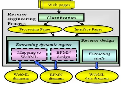
As shown in Figure 1, the proposed approach allows providing a model based abstract view of the considered Web application. Therefore, WebML and business pro-cess diagrams are generated from an application code (HTML + PHP) and a potential database. It is a semi-automatic process assisted by the designer.
In the following, we present the two phases involved in the reverse-engineering process of legacy Web appli-cations, namely, classification and reverse-design.
3.1 Classification
This phase allows classifying Web application pages into two categories: Interface Pages and Processing Pages. The aim of this phase is to distinguish between pages that reflect the user behaviour (Interface Pages) and those that reflect the system behaviour (Processing Pages).
Interface Pages: Called also Static Pages. These
pages contain only the HTML code that runs on the Web browser. They are served by the Web server and they do not need to be preprocessed by the application server. These are HTML pages whose code is accessi-ble by the user.
Processing Pages: Called also Active Pages. These
pages contain a mixture of HTML tags and executable code. When an active page is requested, the application server pre-processes and integrates data from various resources such as Web objects or databases to produce a final HTML Web page sent to the browser. These are the PHP pages whose code is not accessible by the user.
3.2 Reverse-design
This phase aims at extracting design models (hyper-text, data and BPMN models) from Web applications code (HTML+PHP). For this end, we extend an on-tology based Web application reverse-engineering ap-proach [2]. In its first version, this apap-proach generates only data models covering only static aspect of the Web application. In its new version, it generates also BPMN and WebML hypertext models to cover dynamic aspect of the Web application.
3.2.1 Extracting static aspect
It consists in extracting WebML data diagram from the Interface Pages. The intuition underlying this approach is: a WebML data model is hidden under the user in-terface of a Web application. This inin-terface exposes
HTML pages to their users’ browsers, possibly enhanced with client-side scripts in different languages. HTML pages contain usually, forms, tables, lists, etc.
Figure 2: Process of extracting static aspect [2].
Extracting static aspect consists of three successive stages (Figure 2): First is the extraction of useful infor-mation from HTML pages. Second stage is the analy-sis of the extracted information using domain ontology. Last stage is the generation of corresponding WebML data diagram. For more details, refer to [2].
3.2.2 Extracting dynamic aspect
It consists in extracting business process and WebML hypertext diagrams from the Processing pages. The in-tuition underlying this approach is: a business process model can be extracted from PHP code of a Web appli-cation.
Extracting dynamic aspect consists of two succes-sive stages (Figure 1): First is the business process de-sign. Second stage is mapping business processes to
WebML.
A- Business process design
diagrams, representing the tasks to be executed at ab-stract level. The designer can annotate the model by selecting the kind of expected implementation of each task, by mapping some of them to services. In particu-lar, with respect to service invocation, it is possible to specify whether the service has to be modelled and im-plemented within the system (internal), shall be invoked as a non-semantic already implemented service (exter-nal), or needs to be searched and invoked by means of semantic discovery and invocation techniques (seman-tic).
For an automatic extracting of a business process model from a Web application, we propose to use the following rules:
For Interfaces Pages
• Each HTML page will be translated into a BPMN activity.
• An HTML page, allowing data acquisition (e.g., HTML forms), corresponds to an activity that re-ceives a message.
• An HTML page, allowing only data display, cor-responds to an activity that sends back a message.
• An HTML page, that invokes PHP page, corre-sponds to an activity that calls a service.
• An hypertext link between two HTML pages is translated into a link between the two correspond-ing activities.
• All activities that correspond to HTML pages are grouped in a single lane.
For Processing Pages
• Each PHP page is translated into a BPMN lane.
• Each method in a PHP page is translated into an activity.
• A method in a PHP page, which does not include an HTML code, corresponds to a processing activ-ity.
• A method in a PHP page, which includes an HTML code for the data acquisition (e.g., HTML forms), corresponds to an activity that receives a message.
• A method in a PHP page, which includes an HTML code for displaying data, corresponds to an activity that sends back a message.
• Methods of the same PHP page are translated into activities in the same lane.
• The call for a method (i.e., when a method invokes a method in the same PHP page) is translated as a link between the two corresponding activities of the same lane.
• A link, between two PHP pages, is translated into link between the two corresponding lanes.
• A link, between an HTML page and a PHP page, is translated into a link between two lanes.
B- Mapping Business Process to WebML
Once the business process has been designed, work-flow constraints must be turned into navigation con-straints among the pages of the activities of the hyper-text and into data queries on the workflow metadata for checking the status of the process, thus ensuring that the data shown by the application and user navigation re-spect the constraints described by the process specifica-tion. This applies both to the human-consumed pieces of contents (i.e., Interface Pages) and to the machine-consumed contents (i.e., Processing Pages).
For semi-automatic transformation of BPMN dia-grams to WebML diadia-grams, we must follow the next:
• For a Web service lane, each activity in the BPMN model is converted in a WebML activity (an ’A’-labeled area) populated with a default unit (i.e., Solicit units for the BPMN activities that receive
• A suite of Response or Solicit units are grouped in the same WebML page.
• Then the WebML activities are connected by proper links with a well defined semantic to indicate the beginning of an activity (’S’-labeled links) or its end (’C’-labeled links).
• Finally the data model is enriched with Case and Activity concepts that are populated, during the life
of the application, according to the enactment of the BPMN model (a case instance is created at the start of a new process and an activity instance is created at the start of a new activity).
• Additionally, it is possible to annotate the activi-ties, thus allowing the designer to map the activity to a coarse hypertext that implements the speci-fied behaviour on the specispeci-fied data. For instance, if an activity must perform a standard Web ser-vice invocation, it can be translated into a chain of operations consisting of: (a) transforming ap-plication data into suitable format for the subse-quent Web service call (Lowering); (b) invoking the remote service with the specified parameters; (c) transforming the response data into suitable in-ternal format (Lifting); and (d) storing inin-ternal ap-plication data. In any case, the designer is in charge of refining and detailing the specification of the hy-pertext models.
4 The approach motivation
Our work has been motivated by the proposed approach in [4]. It is a model-driven methodology to design and develop semantic Web services, described according to the emerging WSMO standard (Web Service Modelling Ontology [10]). In particular, authors show that busi-ness processes and Web applications engineering mod-els have sufficient expressive power to support the semi-automatic extraction of semantic descriptions (i.e., WSMO ontologies, goals, Web services, and mediators). Their method is based on existing models for the specification
of business processes (BPMN) combined with Web ap-plications engineering models (WebML) for designing and developing semantically rich Web services. The proposed approach leads from an abstract view of the business needs to a concrete implementation of the ap-plication, by means of several design steps; high level models are transformed into software components.
Figure 3: Overall picture of the extraction of semantic description of
Web services.
Figure 3 summarizes the extraction of semantic de-scription of services from the application design. The design flow represents the main steps of the develop-ment process. The various steps produce some inter-mediate artefacts (BPMN models, WebML skeletons, data models, hypertext models), possibly enriched by imported ontological descriptions (on top of Figure 3) and are exploited for devising the set of WSMO spec-ifications (at the bottom of Figure 3). Descriptions of Web services (both in terms of capabilities and of their choreography interface), goals and mediators are de-rived from business process models and WebML mod-els, whereas the implementation of the application front-end and of the services is automatically generated from the high-level models.
5 Running Example
5.1 Example description
For the discussion we will consider a running exam-ple derived from the Shipment Discovery scenario pro-posed by Blue Company. Due to the limited length of the paper, we don’t present the whole application code, but we only present the architecture of the Web appli-cation implemented by the Blue Company (Figure 4).
Figure 4: The Web application architecture.
Blue Customers acquire information about the prod-uct to be shipped through the Shipment Interface. This information represents the selection criteria of the ade-quate operation selected later. The Shipment Interface deals with a Middle Program which carries the selec-tion criteria to a Discovery Engine. When the Discovery Engine returns a list of operations offering a shipment
service compatible with the selection criteria, the Mid-dle Program invokes the returned operations to obtain
actual shipment offers. Finally the customer chooses one offer through the Shipment Interface to achieve its request.
5.2 Web application reverse-engineering process
For checking our approach, we developed a tool called OntoWeR+. The tool allows generating WebML data diagrams using domain ontology. It also allows ex-tracting BPMN diagrams from Web applications and transforming them into WebML hypertext models. The tool allows representing only valid diagrams so that the translation to WebML is always guaranteed. Genera-tion rules for hypertexts have been built based on the experience and the theory presented in [3].
The generated diagrams by OntoWeR+ from the pre-sented Web application above are as follow:
5.2.1 Extracting static aspect
Figure 5 shows the WebML data diagram used by the Shipment Web application. The data diagram has three
main domain entities: Shipment, describing each ship-ping; ShipmentOperation, describing Blue shipment op-eration; and Location, describing the geographical en-tities involved in the shipment process. Each Shipment is related to a ShipmentOperation and to an Origin and Destination Location. Each ShipmentOperation is
con-nected to several Location entities representing ship-ment locations and pick up points. Both the Location and the ShipmentOperation entities have some sub en-tities in order to easily specialize their characteristics.
Figure 5: A portion of the WebML data diagram used by the Ship-ment Web application.
The data diagram includes also a very simple model for describing the status of the process: entity Case tracks the execution of the process instances and entity Activity registers all the activity instances performed
Figure 6: Workflow representing the interaction of the running
ex-ample (BPMN notation).
5.2.2 Extracting dynamic aspect
A- Business process design
The BPMN diagram of the running case is repre-sented in Figure 6 which describes the shipment man-agement.
From the Interface Pages we obtained the Shipment Interface lane. From the Processing Pages we obtained
the remaining lanes.
B- Mapping Business process to WebML
The hypertext models have been automatically gen-erated from the BPMN specification of Figure 6 and then have been manually refined by the designer.
• Mapping Shipment Interface lane into WebML hy-pertext diagram.
Figure 7 shows a WebML hypertext model repre-senting a fragment of the Blue Web application: a home page called Select Product to Ship allows the customer to choose a product (with Status "Not shipped") from the Products List index unit. When a product is cho-sen, the ’S’-link starts the Organize Shipment activity, showing the Product Details data unit in the Organize Shipment page, together with a form (Search Shipment
Offers). The data submission triggers the invocation of
a shipment operation (Search Shipment Offers request-response unit), whose results are lifted by the Store Ship-ment Offers XML-in unit. The activity is completed
(’C’-link) and following one is started. The Select ment Offer page is shown, containing a list of
Ship-ment Offers (an index unit displaying the resulting
op-erations). The customer chooses an offer and thus trig-gers the Confirm Shipment Offer request-response unit, whose results are stored locally. Finally, the customer is redirected to the home page.
Figure 7: The hypertext WebML diagram corresponding to the Ship-ment Interface lane of the BPMN.
Figure 8: The hypertext WebML diagram corresponding to the Mid-dle program lane of the BPMN.
Figure 8 shows the hypertext WebML specification of the Blue Middle Program. The hypertext diagram implements the Middle Program lane of the BPMN di-agram. In the upper part of Figure 6, the searchShip-mentSolicit unit implements the first activity of the lane,
waiting for an incoming message. The ShipmentRe-quest is received by searchShipmentSolicit and is passed
to the Send Selection Criteria activity. The Send Se-lection Criteria unit sends the seSe-lection criteria to the
Discovery Engine. The Discovery Engine returns a set
of operations compatible with the selection criteria and, for each returned operation, an appropriate XSLT style sheet describes the Lowering and Lifting; the resulting operations are stored by Store Selection Criteria Re-sult unit. Then, the Invoke Offer Operations activity
is repeated for each valid returned operation. The ac-tivity consists of a request for a shipment offer, made by the Offer Operation Invoker unit. The proper XSLT style sheets for the Lowering and Lifting are selected according to the results of Discovery Engine. Each re-turned offer is stored by Add Offer unit. Finally, Send Offers activity prepares the results of the
ShipmentRe-quest (Extract Valid Offers unit), converts them to the
Blue data model (Lowering unit) and returns them to the customer (ShipmentOfferResponse unit). Once the customer selects one of the offers, the Receive Chosen Offer activity is triggered (lower part in the Figure 8).
The confirmShipOfferSolicit receives the message and the previously stored offer is retrieved within the In-voke Shipment Operation activity (Extract Confirmed
Offer unit). Then the shipment message is composed
by Lowering with the appropriate XSTL style sheet and Shipment Operation Invoker sends the message to the
discovered shipment operation. Finally ShipmentCon-firmationResponse sends a confirmation message to the
customer about the result of the shipment operation.
6 Conclusion and perspectives
In this paper, we propose an extended approach that allows generating WebML and business process
dia-grams, from the Web application code (HTML + PHP). This work is an extension of an ontology based Web application reverse-engineering approach [2]. In its old version, this approach covered only static aspect by a simple data diagram. In its current version, the ap-proach covers also dynamic aspect of the Web appli-cation by BPMN and WebML hypertext diagrams. A tool has been implemented for supporting the proposed approach in this paper.
The approach was applied to a simulated project with the aim of testing, improving and evaluating the approach. Due to the less availability of the Web ap-plications code, the decision to carry out the validation of the approach through a "simulated project scenario" was considered to be the optimal approach evaluation strategy.
1. Phase of reverse-engineering legacy Web applica-tions: This phase consist in extracting WebML and BPMN models from Web application code. It is a semi-automatic phase shared between the system and the designer.
2. Phase of semantic Web services engineering: this phase generates the implementation code of Web services, as well as the remaining WSMO compo-nents (Web services, goals and mediators). It is a semi-automatic phase shared between the system and the programmer.
References
[1] Berners-Lee T., Hendler J., and Lasilla O., The Semantic
Web. Scientific American, May 2001.
[2] Bouchiha Dj., Malki M., Benslimane S-M. Ontology
Based Web Application Reverse-Engineering Approach.
INFOCOMP (Journal of Computer Science) VOLUME
6-N. Pages: 37-46. 1-MARCH 2007.
[3] Brambilla M., Generation of webml web application
models from business process specifications. In
Proceed-ings of the 6th International Conference on Web
En-gineering (ICWE 2006). ACM Press, New York, NY,
USA, 85-86. 2006.
[4] Brambilla M., Ceri S., and Facca F-M., Model-Driven
Design and Development of Semantic Web Service
Ap-plications. ACM Transactions on Internet Technology
(TOIT), Volume 8, Issue 1, November 2007.
[5] Ceri S., Fraternali P., Bongio A., Brambilla M., Comai
S., and Matera M., Designing Data-Intensive Web
Appli-cations. IMorgan Kaufmann, San Francisco, CA, USA.
2002.
[6] De Lucia A., Francese R., Scanniello G., and
Tor-tora G., Reengineering Web Applications Based on
Cloned Pattern Analysis. Proceedings of the 12th IEEE
International Workshop on Program Comprehension
(IWPC’04). 2004.
[7] Draheim D., Lutteroth C., and Weber G., A Source
Code Independent Reverse Engineering Tool for
Dy-namic Web Sites. Proc. 9th European Conference on
Software Maintenance and Reengineering (CSMR’05),
pp168-177. 2005.
[8] Katsimpa T., Panagis Y., Sakkopoulos E., Tzimas G.,
and Tsakalidis A., Application Modelling using Reverse
Engineering Techniques. Proceedings Symposium on
Applied Computing (SAC’06), pp1250-1255. 2006.
[9] Patel R., Coenen F., Martin R., and Archer L.,
RE-VERSE ENGINEERING OF WEB APPLICATIONS: A
TECHNICAL REVIEW. June/July 2007.
[10] Wang, H. H., Gibbins, N., Payne, T., Saleh, A. and Sun,
J. A Formal Semantic Model of the Semantic Web
Ser-vice Ontology (WSMO). In: Twelfth IEEE International
Conference on Engineering of Complex Computer
Sys-tems, Auckland, New Zealand, July 11 - 14, 2007.
[11] Wang H-H., Gibbins N., Payne T-R., and Saleh A.,
TTransitioning Applications to Semantic Web Services:
An Automated Formal Approach. Journal of
Interoper-ability in Business Information Systems (IBIS), Vol. 3/6,
![Figure 2: Process of extracting static aspect [2].](https://thumb-us.123doks.com/thumbv2/123dok_us/8366449.1673550/3.596.317.512.186.383/figure-process-of-extracting-static-aspect.webp)


