Vol. 04, Issue 02 (February. 2014), ||V6|| PP 46-52
Analysis of Transmitting 40Gb/s CWDM Based on Extinction
Value and Fiber Length Using EDFA
Yasser Almalaq
1, Mohammad Matin
21,2Electrical & Computer Engineering Department, Daniel Felix Ritchie School of Engineering and Computer
Science, University of Denver
Abstract: - It is difficult in optical communication systems to predict the final signal at the customer side because of using various components and the effect of many features. Simulation helps to analyze and expect the performance before any actual hardware is done. In the proposed research, Optisystem 12th version software is used in order to analyze transmitting 40Gb/s, 10Gb/s for each channel, in four channels of coarse wavelength division multiplexing (CWDM) from the transmitter to the receiver based on extinction ratio and the distance of the optical fiber until 100km. An Erbium-Doped Fiber Amplifier (EDFA) is used for long distances. The objective of the simulation is to certify that the received signals are not affected by the noise and attenuation so they are undamaged and in good condition by using bit error rate (BER) analyzer. From the simulation obtained, maximum Q factor, eye height, and threshold decreased as the fiber length increased, and as the value of the extinction ratio increased, the eye height increased but threshold decreased. The results of the CWDM are presented in this paper.
Keywords: -Bit Error Rate (BER), Coarse Wavelength Division Multiplexing (CWDM), Erbium-Doped Fiber Amplifier (EDFA),
I.
INTRODUCTION
In these days, there is severe increase in the need for more bandwidth and is probably will continue for the feature. In order to fulfill this need, telecommunication companies have to investigate on increasing their channels’ capacity with the lowest cost possible. Using wavelength division multiplexing (WDM) seems that it is one solution of reducing the cost. With WDM, number of wavelengths can be transmitted by one single fiber at the same time. Backing various transmission formats is another powerful tool that WDM has. Therefore, at any data rate, various formats signals can be transmitted independently and at the same time by the same fiber without the need for common signal structure by using separate wavelengths.
Coarse wavelength division multiplexing (CWDM) and dense wavelength division multiplexing (DWDM) are two types of WDM. CWDM is getting more attention in access, metro, and cable TV network because it can transmit more bandwidth with low cost comparing to DWDM. CWDM can carry wavelengths ranging between 1270 nm to 1610 nm with 20 nm channel spacing and requires inexpensive uncooled and direct modulated lasers result in low power consumption.
Although CWDM networks demand reduced cost compared to DWDM networks, repeaters or amplifiers are needed to expand the reach of the CWDM networks.Transmission at higher rates can be achieved when optical amplifiers such as erbium doped fiber amplifier (EDFA), semiconductor optical amplifier (SOA), Raman, or hybrid are used in the CWDM network. At the present time, a SOA is the exclusive suitable solution for amplification as a result of its simple design and reduced cost. To use SOAs in CWDM network, they should have adequate broad to deal with at least four channels. Different kinds of optical amplifiers are available in the market and depending on the application, specific one can be chosen. However, in terms of the price, the Raman amplifier is the most expensive one.
This paper studies mainly the affect of the extinction ratio and the fiber length on CWDM network with the use of EDFA. Optisystem software is used to simulate the CWDM link. By using bit error rate (BER) analyzer, different parameters such as maximum Q factor, minimum bit error rate, eye height, and threshold have been tested.
II.
DESCRIPTION
OF
THE
OPTICAL
DESIGN
Avalanche photodetectors (APDs) are used to convert the received optical signals to electrical signals. Then, These electrical signals are amplified using Trans-impedance Amplifier (TIAs) and the amplified signals are filtered through a second order low pass Gaussian filter. Bit Error Rate (BER) analyzers are used to realize the quality of the output signal for each channel. A schematic design of four channels CWDM is presented in Figure 1.
Fig1: Design schematic.
III.
SIMULATION
DESIGN
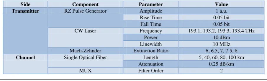
The simulation is performed by the use of Optisystem software. Optisystem gives the ability to the designer to change the design and the parameters to get better results. As shown in figure 2 the transmitter side consists of 4 transmitters at 193.1, 193.2, 193.3, and 193.4 THzwith almost 100GHz spacing between the channels. Then, the media is WDM MUX works as CWDM, optical fiber with different lengths, EDFA, and WDM DEMUX. In the receiver side, photodetector APDs, low pass Gaussian filters, TIAs, and BER analyzers. The designed system is shown in Figure 2 and list of the parameters used are given in Table 1.
Fig2: Simulation Design
Table 1: Values of some components used in the simulation
Side Component Parameter Value
Transmitter RZ Pulse Generator Amplitude 1 a.u.
Rise Time 0.05 bit
Fall Time 0.05 bit
CW Laser Frequency 193.1, 193.2, 193.3, 193.4 THz
Power 10 dBm
Linewidth 10 MHz
Mach-Zehnder Extinction Ratio 6, 6.5, 7, 7.5, 8
IV.
RESULTS
AND
DISCUSSION
4.1 Eye DiagramEye diagram or also known as eye pattern in telecommunication is an old technique used in order to evaluate the received signal. Totally opened eye pattern represents the lowest level of distortion. BER analyzerscreate eye diagrams by making a pseudorandom arrangement of 1s and 0s in a symmetric rate but in an arbitrary manner. In Optisystem, eye diagram, which can be found in the BER analyzer show various traces of modulated signal in order to create an eye diagram. Because of the shape of the pattern that looks as if it is an eye, it is called an eye diagram.
4.1.1 Eye Diagram of 5km 6dB
The eye diagrams shown in figure 3 are obtained when the length of the fiber is 5km and extinction ratio is 6dB without using EDFA.
(a) (b)
(C) (d)
Fig3: Eye diagram of 5km 6dB. a) Eye diagram of channel 1. b) Eye diagram of channel 2. c) Eye diagram of channel 3. d) Eye diagram of channel 4.
4.1.2 Eye Diagram of 40km 8dB Using EDFA
As shown in figure 4, eye diagrams are presented when 40km fiber length, 8dB extinction ratio, and EDFA are used.
DUMX Filter Order 2
EFDA Length 15 m
Receiver APD Photodetector Responsivity 1 A/W
Dark Current 10 nA
Low Pass Gaussian Filter Cutoff Frequency 0.75*Bit rate
TIA Voltage Gain 10 Ohm
(a) (b)
(C) (d)
Fig4: Eye diagram of 5km 6dB. a) Eye diagram of channel 1. b) Eye diagram of channel 2. c) Eye diagram of channel 3. d) Eye diagram of channel 4.
4.1 Effect of Varying Fiber Length with Using EDFA
Along the fiber, as the fiber length increased, the noise will be increased and the power will be lost as well. In this section, the effect of varying fiber length between 40km to 100km is tested. EDFA is used for this range of distances. The test is done by the use of BER analyzer, which can test maximum Q factor, minimum bit error rate, eye height, and threshold. Figure 4 shows the maximum Q factor versus fiber length ranges between 40km and 100km. The maximum Q factor decreased as the fiber length increased as shown in figure 5.
Fig5: Maximum Q factor vs. fiber length
Fig6: Minimum BER vs. fiber length
As previously mentioned, totally opened eye pattern represents the lowest level of distortion. Figure 7 shows that the eye height decreased as the fiber length increased.That means, the distortion increased as the fiber length increased. As can be observed from figure 7, channel 1, which has larger wavelength, has larger eye height than channel 4, which has lower wavelength.
Fig7: Eye height vs. fiber length
Threshold decreased as the fiber length increased as shown in figure 8. As can be observed from the figure below first channel, which has higher wavelength has larger threshold than the fourth channel, whichhas lower one.
Fig8: Threshold vs. fiber length
4.1 Effect of Extinction Ratio on 5km Fiber Length
Fig9: Maximum Q factor vs. extinction ratio
From figure 10, the minimum BER is almost the same for all the channels along the extinction ratio ranging from 6 to 8. The minimum BER ranges between 6.27E-22 and 5.04E-18.
Fig10: Minimum BER vs. extinction ratio
As can be observed from figure 11, eye height increased as the extinction ratio increased. Therefore, to minimize the distortion, the extinction ratio should have larger value.
Fig11: Eye height vs. extinction ratio
V.
CONCLUSION
In this paper, 4 channels CWDM have been simulated. The powerful of CWDM comes from its large bandwidth with low cost. An EDFA has been used for long distances. As can be observed from the results, maximum Q factor, eye height, and threshold decreased as the fiber length increased. On the other hand, it does not appear that the extinction ratio has a specific pattern on maximum Q factor and minimum BER. However, as the value of extinction ratio increased, eye height increased but threshold decreased.
REFERENCES
[1] Gerd Keiser, OPTICAL FIBER COMMUNICTION, 2013th ed. New Delhi, India: McGraw Hill Education.
[2] Jincy Johny and Sreenesh Shashidharan , "Design and Simulation of a Radio Over Fiber System and its Performance Analysis," IEEE Optical Networking Technologies and Data Security , pp. 536-539, 2012. [3] Seoijin Park, R. Leavitt, R. Enck, V. Luciani, Y. Hu, P. J. S. Heim, D. Bowler, and M. Dagenais ,
"Semiconductor Optical Amplifier for CWDM Operating Over 1540–1620 nm," IEEE PHOTONICS TECHNOLOGY LETTERS, vol. 17, no. 5, pp. 980-982, MAY 2005.
[4] Atousa Assadihaghi, Hassan Teimoori, Ronald Millett, Abdessamad Benhsaien, Valery Tolstikhin, Trevor Hall, and Karin Hinzer , "O-band Semiconductor Optical Amplifier Design for CWDM Applications," IEEE, pp. 89-92, 2008.
[5] Kenneth C. Reichmann, Patrick P. Iannone, Xiang Zhou, Nicholas J. Frigo, and B. Roe Hemenway , "240-km CWDM Transmission Using Cascaded SOA Raman Hybrid Amplifiers With 70-nm Bandwidth," IEEE PHOTONICS TECHNOLOGY LETTERS, vol. 18, no. 2, pp. 328-330, JANUARY 2006.
[6] Khadijah Ismail, P. Susthitha Menon, Hesham A. Bakarman, Ahmad Ashrif A Bakar, and Norhana Arsad , "Performance of 18 Channel CWDM System with Inline Semiconductor Optical Amplifier," in 3rd International Conference on Photonics 2012, 2012, pp. 215-219.
[7] P.P. Hema and Prof. A.Sangeetha, "Analysis of four channel CWDM Transceiver Modules based on Extinction Ratio and with the use of EDFA," International Journal of Engineering and Technology (IJET) , vol. 5, no. 3, pp. 2895-2902, Jun-Jul 2013.