(UDC: 611.718.087.3)
Finite element analysis of CT based femur model using finite element
program PAK
S.Vulovic1*,N.Korunovic2, M.Trajanovic2, N.Grujovic3, N. Vitkovic2
1
Faculty of Information Technology, Tadeusa Koscucka 63, Beograd Email: [email protected]
2
Faculty of Mechanical Engineering, Aleksandra Medvedeva 14, Nis Email: [email protected]
3
Faculty of Mechanical Engineering, Sestre Janjic 6, Kragujevac Email: [email protected]
*Corresponding author
Abstract
In this paper a structural analysis of femur using Finite Element method is presented. The whole processes is described, starting from polygonal model generation based on CT data, trough construction of CAD model and mesh generation, to defining the loads and material properties. In order to accomplish those tasks, CAD software CATIA and the FEM software PAK have been used.
Keywords: femur, finite element method, computed tomography (CT)
1. Introduction
The application of computer aided technologies in medicine is here demonstrated through the use of computer models for bone-joint system functioning simulation. This kind of approach facilitates planning of operative procedures and enables production of custom implants. Therefore, a large number of multidisciplinary researches have lately been initiated, which engage both researchers from both technical and medicine branches.
Biomechanical phenomena such as bone aging, osteoporosis and bone loss in microgravity affect bone strength by changing its structural geometry. Therefore, the investigation of the individual effects of structural and geometrical parameters on the bone strength can lead to better understanding of the mechanisms and risk factors associated with a specific bone disease. Human body is neat and complicated; stress may cause great irreversible damages to bones and soft tissues, as muscles for instance. The analysis presented in this study is a preliminary demonstration of typical stress state in femur.
into account is possible by defining material properties per each finite element. In such case, extremely fine meshing is required for precise analysis of bone with inhomogeneous properties. On the other side, handling of material property data element by element is impractical by general finite-element codes.
Three-dimensional finite element (FE) analysis is the only available technique that accounts for the complexity of femur geometry and its material distribution, as may be seen from [Ranković et al. 2007] or [Theodorou et al. 2009]. A major challenge for applying FE models is the generation of quality meshes for patient-specific data acquired from medical images. The objective of this work was to develop a semi-automatic parametric technique for creating FE models of the femur, starting from CT data. Similar to the geometry-based techniques, our FE mesh creates a smooth surface geometry. Also, in this paper, a procedure for stress analysis is described. This type of analysis can be used for durability estimation of a healthy bone, mechanically damaged bone (fractured), or bone damaged by degenerative processes (for example osteoporosis).
2. From CT scan to FE model
A common approach to bone modeling for FEA is often taken, such that finite elements are built inside the outer manifold of a bone and material properties are then assigned per element, based on apparent density taken from CT scan (as described in [Taddei et al. 2004]). The advantage of such an approach is fast FE model building and capturing large variation of elastic modulus over the model. Nevertheless, the disadvantage is that the thin segments, such as cancellous bone, are not modeled with sufficient precision unless finite elements are very small, which in turn results in very large FE models. For that reason, a different approach has been used here, where geometrical model, based on CT scan has been divided into zones, to which are assigned equivalent elastic moduli and appropriate mesh.
FE model of femur described in this paper is based on CT scans of a patient's lower extremities. The main phases, through which the model has been built, are:
1. Creation of the polygonal model on the basis of CT scan
2. CAD model creation: polygonal model cleaning and healing, creation of NURBS surfaces and volumes
3. FE model creation: zoning, assigning material model, mesh creation
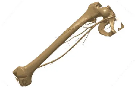
In the first phase, CT scan of a patient who had suffered from vascular system related problems has been used, which resulted in isolating the point cloud and corresponding polygonal model that contained not only femur, but also extra objects such as parts of vascular system or parts of surrounding bones (Fig. 1.).
In the second phase, the model has been cleaned and healed, so that irregularities were corrected, which were caused by difficulties in recognizing the boundaries between cancellous and cortical bone structure or by osteoporosis (Fig. 2).
Fig. 2. Irregularities on polygonal model created from CT scan, which have to be corrected before CAD model creation
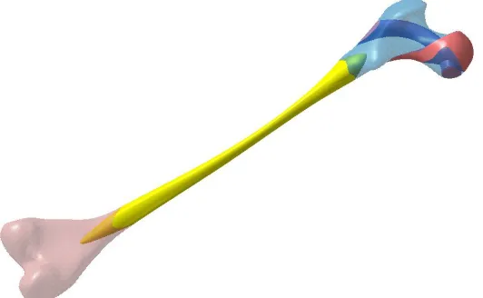
Based on the polygonal model, NURBS surfaces were created, which represent the outer manifold of femur and the border of inner medullary cavity. Then, the other surfaces were created, using advanced 3D CAD features, which divide the inside of femur into zones corresponding to regions with different inner structure, according to the idea from paper by [Rudman et al. 2006]. The construction of three-dimensional zones, in contrast to 2D zones described in the mentioned paper, dictated the use of advanced modeling features in CATIA. Then Solid feature, filling the whole outer manifold has then been created and divided into segments using the NURBS surfaces, as shown in Fig. 3.
In the third phase, the FE model based on CAD model has been constructed, as described in the next section.
3. Analysis of femur by PAK software
The static linear analysis of intact femur for a case of one-legged stance was performed. The software used in the analysis, with the generated finite element mesh of the femur, was PAK. PAK [Kojic et al. 1998-2009] is a system of programs for linear and nonlinear, static and dynamic structural analysis, heat conduction, fluid mechanics with heat transfer, coupled problems, biomechanics, fracture mechanics and fatigue.
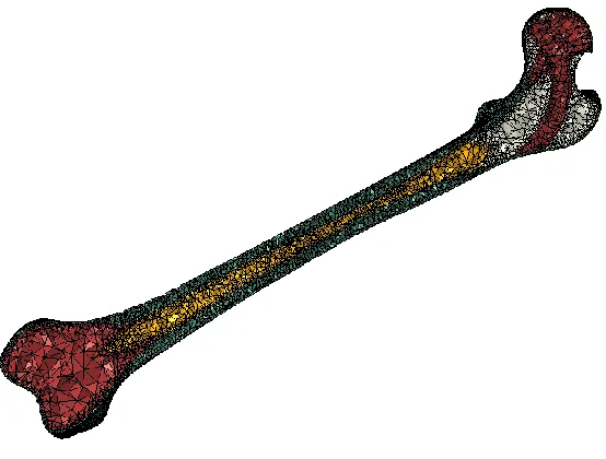
Different material properties were attributed to different femoral regions, as shown in Fig. 4. Corresponding material constants are given in Table 1. The values given in the table have been taken from [Rudman et al. 2006], except for Bone marrow modulus, which has been chosen to be very small in order to minimize its influence on bone stiffness.
Young‘s module (MPa) Poisson‘s Ratio Color
Cancellous 100 0.3 White
Cancellous stiffer 400 0.3 Red
Bone marrow 1 0.3 Yellow
Cortical bone 17000 0.3 Green
Table 1. Material Properties assigned to femur
The distal end of the femur model (condylar surface), was fully fixed, Fig. 5. The load consisting of a joint reaction force (700 N) applied to the femoral head and an abductor muscle force (300 N) applied at the great trochanter, [Sowmianarayanan et al. 2006].
Fig. 5. FE model of femur with boundary condition
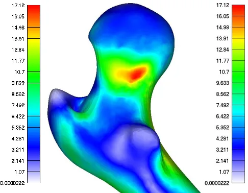
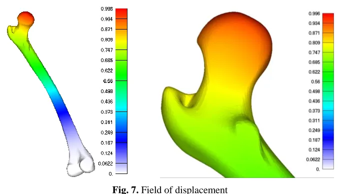
The maximum stress within the bone is 17.12 MPa, Fig. 6. The maximum normal strain under this stress is 0.996 mm, Fig. 7.
Fig. 7. Field of displacement
Even though the results shown in previous images are obtained using a load case obtained from literature (representing one-leg stance) as well as average material properties, it is considered that they give an indication of critical places considering equivalent stress in a femur of a specific patient (e.g. femur neck in Fig.6). Using this modeling approach, a next course of action, considering medical treatment of the patient or surgery planning, may be undertaken.
4. Conclusions
In this paper a full process of static structure analysis of femur is described. The process includes generating 3D model from CT-Scan data, meshing, assigning material properties and analyzing the structure. During the process, we also study the methods for mesh quality enhancement and apply this idea using specific software. In the presented work, the internal zone of 3D FE model, corresponding to cancellous bone, is further subdivided into a number of subzones of lower or larger stiffness, which is an approach until now only used in 2D analysis. For this purpose, free form parametric 3D shapes had to be created inside the CAD model that was further used as a basis for FE model preparation.
The approach described in this paper has several issues that need improvments. The real skeletal structure includes bones and soft tissues, so both should be included in a future model. Also, the physical conditions around the joint are more complicated than this models predicts. How to build the detailed 3D structure of femur is a problem that needs deeper consideration. Material properties of the bone and tissues are more complex than presented here. For those reasons, this paper may be considered as an introduction to analysis of biological structures by applying finite element method and FEM software.
Извод
Анализа коначним елементима модела бутне кости на основу CT-a коришћењем програма PAK
S.Vulovic1*,N.Korunovic2, M.Trajanovic2, N.Grujovic3, N. Vitkovic2
1
Faculty of Information Technology, Tadeusa Koscucka 63, Beograd Email: [email protected]
2
Faculty of Mechanical Engineering, Aleksandra Medvedeva 14, Nis Email: [email protected]
3
Faculty of Mechanical Engineering, Sestre Janjic 6, Kragujevac Email: [email protected]
*Corresponding author
Резиме
У овом раду је рађена структурна анализа бутне кости користећи Метод Коначних Елемената. Описан је цео поступак, почевши од генерисања полигоналног модела на основу CT података и конструисања CAD модела и генерисања мреже до дефинисања оптерећења и својстава материјала. У циљу обављања ових задатака коришћени су CAD софтвер CATIA и FEM софтвер PAK.
Keywords: Бутна кост, метод коначних елеметана, компјутерска томографија (CT)
References
M. Kojic, R. Slavkovic, M. Zivkovic, N. Grujovic, N. Filipovic, PAK- Finite element program for linear and nonlinear, static and dynamic structural analysis, heat conduction, fluid mechanics with heat transfer, coupled problems, biomechanics, fracture mechanics and fatigue, Faculty of Mech. Engrg, University of Kragujevac; R&D Center for Bioengineering, BioIrc, Kragujevac, 1998; 2009.
Ranković, V., Ristić, B., & Kojić, M. (2007). Internal fixation of femoral bone comminuted fracture: FE analysis. Journal of Serbian Society for Computational Mechanics, 1(1), 120-128.
Rudman KE, Aspden RM, Meakin JR (2006). Compression or tension? The stress distribution in the proximal femur. BioMedical Engineering OnLine, 5:12 doi:10.1186/1475-925X-5-12.
Sowmianarayanan.S, Chandrasekaran A, Krishnakumar R. Finite Element Analysis of Proximal Femur Nail for Subtrochanteric Fractured Femur, 2006 International ANSYS Conference Proceedings.
Taddei F., Pancanti A., Viceconti M., An improved method for the automatic mapping of computed tomography numbers onto finite element models, Medical Engineering & Physics 26 (2004) 61–69.