(DOI: 10.24874/jsscm.2017.11.02.02)
Numerical Study of Plasticity Effects in Uniform Residual Stresses
Measurement by Ring-Core Technique
H. Heidary1*, M. Sadri 2, N. Zarif Karimi 3, C. Fragassa 3
1 Department of Mechanical Engineering, Tafresh University, Tafresh, Iran
e-mail: [email protected];
2 Department of Mechanical Engineering, Zanjan University, Zanjan, Iran
e-mail: [email protected]
3 Department of Industrial Engineering, University of Bologna, Bologna, Italy
e-mail: [email protected] e-mail: [email protected]. *corresponding author
Abstract
The Ring-Core method is a mechanical technique used to calculate the surface residual stresses in a material. In this paper, plasticity effects on the calculated results of the Ring-Core technique were studied by FEM analysis. For this purpose, the coefficients were obtained from an elastic finite element modeling. Then, the execution of the Ring-Core technique using bilinear elastic-plastic behavior for the material was simulated and finally the relaxed strains due to ring core milling were obtained. The plastic error due to yielding was calculated by comparing the applied stress and calculated stress from the FE simulation. Also, by using the prepared FE model, the effects of various parameters like state of loading, ring geometry and tangent modulus were investigated. Based on the obtained results, a suitable range for the ring diameter was proposed in order for achieves accurate results.
Keywords: Plasticity, residual stress measurement, ring-core, uniform stress
1. Introduction
Residual stresses (RS) were developed from different mechanical or thermal operations such as welding, forging, and machining (Withers and Bhadeshia 2001). Residual stresses can cause brittle fracture, buckling, and SCC so determining and measuring have an important role in structure condition assessments. (Rossini 1996, Dassisti et al. 2012).
In this paper, plasticity error in a uniform RS measurement is investigated by the RC technique using numerical analysis. For this aim, the needed coefficients were obtained from an elastic finite element modeling. Then, the RC technique using bilinear elastic-plastic behavior for the material was simulated and the relaxed strains due to RC milling were obtained. The plastic error due to yielding is evaluated by comparing applied stress and calculated stress from the FE simulation. Also, by using the prepared FE model, the effects of various parameters like state of loading, and tangent modulus have been investigated. Based on the obtained results, a limitation of ring diameter is suggested to obtain a good precision.
2. Principle and theory of RC strain gauge method
The RC method is a mechanical technique used to calculate the surface residual stresses in a material. Mechanical techniques, which involve removing material and monitoring strain relaxation, can often provide the only means of determining deep stresses in components. The introduction of a ring into a residually stressed body changes the stresses distribution around the ring. This occurs because shear and normal stresses on new subsisted surface are zero and any changes of stresses field causing the local strains in the bordering region. Mechanical stresses relaxation’s principles for RS measurement, first suggested by Mathar, in this manner is used for the development of the RC technique (Mathar 1934).
In the most practical applications of this method, the ring is blind with a depth about equal to its diameter that is small compared to the thickness of the test specimen. Unfortunately, the analysis of blind-ring geometry is adequately complicated, so that no closed-form solution is accessible in this case for direct calculation of the residual stresses from the obtained strains. However, for a simpler form of a through-thickness ring in an infinite plate with a uniform RS distribution, a solution can be obtained based on the theory of elasticity. Thus, the first relation between relived strain and original residual stresses will be derived for the through-ring geometry and consequently will be devoted for application to blind rings.
2.1. Through-ring stress and strain analysis
A flat uniform surface area away from edges and other irregularities is chosen by linear elastic behavior of the material as the test specimen of interest.
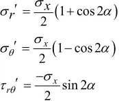
The initial stress state at any point P(R,α) in polar coordinates is:
1 cos 2 2
1 cos 2 2
sin 2 2
x
x r
x r
(1)
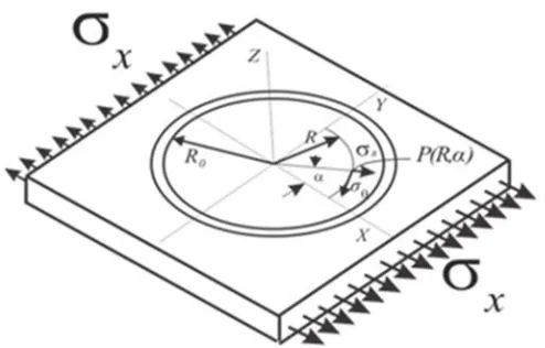
Fig. 1. A through ring on the uni-axial stressed plate
In the created island area, which is completely separated from the surrounding region by the ring, all stress components must be zero everywhere on the ring surface and each point like P.
0
r r
(2)
Subtracting the initial stresses state from the current state gives stress relaxation or stresses varying at point P(R,α) due to ring cutting. That is:
1 cos 2 2
1 cos 2 2
x
r r r
x
(3)
With homogeneous, isotropic and linear-elastic behavior assumption for the plate material and using Hooke’s law for biaxial stresses state, the strain in the radial direction of the point P can be written as bellow:
1 cos 2
1 1
2 2
r E r x A B
A B
E E
(4)
2.2. Blind-ring stress and strain analysis
The introduction of a blind ring on a plate with plane stress state generates a very complex local stress distribution and there has been no available exact solution for this until now and no progress has been made so far towards its solution. Fortunately, it has been demonstrated by various numerical studies that stresses distribution on the plate surface is closely similar to the plate with through-ring in nature and condition of stress distribution. Thus, the relieved strains maybe still estimated in the manner described by Eq. (4).
It follows that the equations are also usable to the blind ring implementation when new
appropriate coefficientsA and Bare used instead of previous confident. Since A andBcould
not be derived from the analytical approach directly, they can just be calculated experimentally or numerically. Compared to the through-ring coefficients, blind-ring coefficients involve
, , , , ,
I I
H H
A A E B B E
D D
(5)
Therefore, Eq. (4) can be rewritten as below and can be used for evaluation of residual stresses by the RC technique:
cos 2r A x y B x y
(6)
According to FE investigations, the effect of dimensionless parameterDO/DI is ignorable. Also x, yand are unknown quantities and should be determined as below.
Three independent measurements ofr are necessary to solve the equations. The ordinary process for measuring the relieved strains is mounting three resistance strain gauges in rosette form on the center of ring before cutting. Such a rosette and position of mounting are shown schematically in Fig. 2.
Fig. 2. Geometrical notation of the groove
The use of commercial rosettes with angles 45 between gauges leads to the simplest
analytical expressions. As indicated in Fig. 2, Eq. (4) can be written for each of the gauges a, b and c, by considering their directions:
cos 2
sin 2
cos 2
a
r x y x y
b
r x y x y
c
r x y x y
A B
A B
A B
(7)
, , , , ,
I I
H H
A A E B B E
D D
(8)
Where α is the angle between gauge 1 and maximum stress. Also, rc, rbandrcare calculated
strains by the ring form strain gauges in direction a, b and c.A andBare constant coefficients and could be obtained experimentally or numerically.
2.3. Constant coefficientA and B
Whether the RS analysis application involves through-ring or blind-ring, the coefficients A and
Bmust be determined for calculating the stresses from the relieved strains. In the case of the through ring, reasonable exact values of the coefficients can be obtained for any particular case by analytical methods, if desired. This can be done by integrating the component of strain parallel to the primary strain-sensing axis of the gauge, over the area of the gauge grid. By giving the details of the grid geometry (line width and spacing, number of lines, etc.); slightly greater accuracy may be obtained by integrating along the individual grid lines. This method cannot be applied to blind ring analysis, because closed-form expressions that relate the relieved strains to the RS in terms of ring depth are not available. Compared to the through-ring coefficients, blind-ring coefficients involve one additional dimensionless variable; namely, the dimensionless blind-ring depth, H D/ I (see Fig. 2). Thus, in a generalized functional form, the coefficients can be expressed as Eq. (5). Basically, the calibration procedure involves calculating the rosette strains under the same applied load or calibration stress,tboth before and after cutting the ring. This procedure is essential to ignore the strain relief effect which may happen due to the initial RS relaxation in the specimen calibration. With this technique, the observed strain difference (before and after ring cutting) is caused only by the applied calibration stress, and is individually related to that the mentioned stress. To calculate the coefficients, only the strains in gauges a and c are necessary, since these gauges are known to be aligned with the principal axes of the specimen. Then a load, P, should be applied to the specimen to develop the desired calibration stresst.
With ideal linear elastic behavior and uniaxial loading condition, the values of coefficients
A andBin Eq. (8) were obtained according to following relation. In this relation,c is applied
stress in direction a, andbefore andafter are strain before and after ring machining in two perpendicular directions. The obtained coefficients are firmly applicable only for the same material, ring and rosette geometry used in a calibration test.
2 2a a c c
r after r before r after r before t
a a c c
r r r r
after before after before t A B (9)
2.4. Plasticity effects on Residual Stresses measurement
When the specimen material has elastic-plastic behavior, the measured strain is not only affected by the RS relaxation effect, but includes the contribution of other effects such as plastic strain. In particular, it can be given by the following relation:
m p c
In which , p andc is the strain component due to the residual stresses, the strain component due to a localized plastic flow and the strain component caused by machining the groove, respectively. Machining strain can be minimized by convenient tool and machining method selection, but plastic strain due to material behavior may cause an error in stresses evaluation.
The plasticity error due to stress concentration effect is a well-known issue in the measurement of high residual stresses with the mechanical stress relaxation technique (Gibmeier, Kornmeier et al. 2000). So, for the cases in which the amount of the calculated stress becomes greater than the validity amount, the plastic deformation effects should be taken into account (Moharami and Sattari-Far 2008).
The problem for hole-drilling method has been investigated by many researchers for different cases, during the last two decades (Schajer 1988, Schajer 1988). Procter and Beaney reported 10% overestimated plastic errors when bars are subjected to full yielding uniaxial loading (Procter and Beaney 1982). Beghini studied a plate with pre-existing hole under mechanical loading to propose a procedure for RS measurement above 50% of the yield strength (Beghini, Bertini et al. 1994, Beghini and Bertini 1998).
3. Finite element analysis
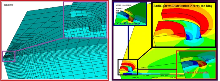
To study the plasticity effects, because of difficulties in experimental research, a finite element method (FEM) was chosen to study the problem. It is the only reasonable way to obtain the desired information or simulate the real experiment. For this purpose, the RC process was simulated by using a commercial finite element code. The ANSYS analysis system was used for the FE-simulation and a parametric model was developed. To ensure the independency of the solution results, the global sizes of the model were selected relatively larger than the ring dimensions. Because of the symmetry in geometry and loading, in order to reduce the required solution time, only one quarter of a finite plate was modeled. The FEM model consisted of about 7500 solid elements. The model and its meshing used for numerical study are depicted in Fig. 3.
Fig. 3. FEM model used in numerical study of RC method and some schematic results
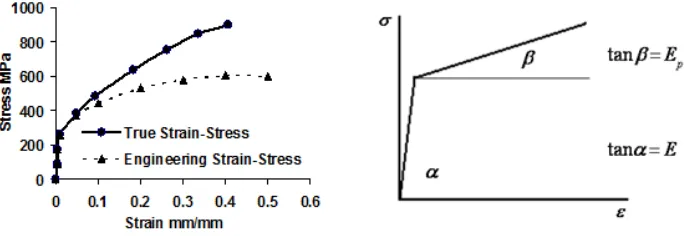
To study the plasticity error in the numerical simulation, the assigned mechanical properties are similar to properties of the steels used in the experiments (previously determined by a tensile test). The true stress-strain curves of the materials are modified by bilinear stress-strain behavior which can be easily recognized by the young modulusE, yield strengthY , tangent modulus
p
E and Isotropic strain hardening condition as shown in Fig. 4.
Fig. 4. Approximation of true stress-strain curve of St. St. with bilinear stress-strain curve for FEM analysis.
The plastic error due to yielding around the ring is calculated by subtracting the applied stress app from the calculated stresscal, divided by the applied stress as expressed by following relation:
% cal app 100app
Plastic Error
(11)
There are some affecting parameters in the plasticity errors determined by the measured results. Ring geometry, material properties, principal stress level and the stress ratio are the main factors. According to numerical studies, plasticity errors are influenced by the following dimensionless parameters:P1H D P/ I, 2 / Y and P3EP/E. For studying the effects of
these parameters, some finite element analyses were conducted. Through this analysis, in consideration of available rosette strain gauge and machining facility, the internal ring dimension was equal to 10 mm. In these analyses, the effects of hardening coefficient
P3 and the residual stress level
P2 for the uniaxial stress field were studied. The values of the affecting parameters studied here are given in Table 1.Parameter Assigned Values
1 /
P H D 0.1, 0.2, 0.3, 0.4, 0.5
2 / Y
P 0.5, 0.55, 0.6, 0.65, 0.7, 0.75, 0.8, 0.85, 0.9, 0.95
3 p/
Table 1. The values of the affecting parameters used in this study.
4. Results and discussion
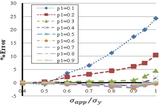
Using the values form Table 1, the influence of dimensionless parametersP P1, 2andP3 on the plasticity error were investigated. By Calculating the FEM strain and introducing the applied stresses and calculated stresses to Eq. (11), the plastic errors can be determined. The obtained
results for the material withEp/E0.05 are shown in Fig. 5.
Fig. 5. Effect of the parameter P1 on plastic error forEp/E0.05
For materials with the value of Ep/Eas given in Table 1, the errors in measured stresses
have similar behavior as shown in Fig. 5, but with different error orders. According to the results, the plasticity error is negligible for calculated stresses being less than 60% of the yield strength of the material. When the calculated stress becomes greater than 60% of the yield strength, errors in the measured results will be significant. The amount of the error increases by increasing the calculated stress.
Based on the figures, the effect of plasticity on RS errors calculating is significant only for
surface stresses. Then, recommended depth should be at leastH 0.3DI which corresponds to
1 0.3
P . Also, asP3 decreases, the maximum error increases due to tending behavior of the
material to a linear elastic state. Therefore, the plasticity error in a uniaxial stress field can be determined as below:
1 2 3
%Error f P P P, , (12)
As can be see from Fig. 5, the influence of P1 on the plastic error is significant only for
surface stresses, then recommended depth should be at leastH0.3DI which corresponds to
1 0.3
P . Also, asEp decreases, the maximum error increases. By paying more attention to Fig.
and the errors decrease. Another point is that, as drilled groove reaches the bottom layer, the plate surface is less affected by the plastic flow and thus the results will be more accurate.
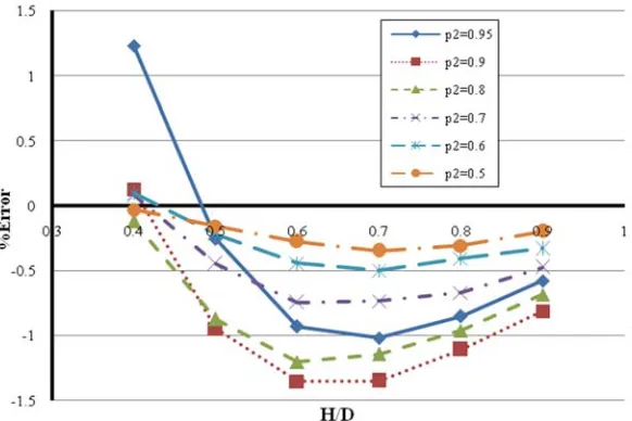
As the final and the most important result, a modified range is proposed for parameterP1 for
various values ofP2, in which the amount of error is less than 1.5 % and can be an acceptable
precision for this method (Fig. 6). Then, for the range obtained from this investigation, the method is modified rather than the results presented by Petrucci and Zuccarelìo. They reached 40 % maximum error for the RC method (Petrucci and Zuccarello 1996),while the result of this paper for the maximum error is about 26 %.
Fig. 6. Modified rings depth Errors
5. Conclusion
In this paper, the RC method was initially developed for the uniform RS calculation and then the plasticity effects on the errors’ results of this method are investigated. Four parameters are considered in order to study their effect on the precision of results. The results show that, for the case of plasticity effects, there are the following considerations:
When the uniaxial RS exceeds more than 65 % of the yield strength, for whichP2 0.6,
the error increases.
Three dimensionless parametersP P1, 2andP3, also effect the accuracy of the RC
technique in uniaxial loading state.
The proposed range arise from this research, eliminates the imperfections of other
methods in measuring RS.
The results show that the error percentage is affected byH D/ , and the accuracy of the
The result for the mentioned range has approximately 1.5 % error which is reasonable for residual stresses using the RC method. This is the most important result of this paper.
The maximum error for this method is about 26 % which is less than the error presented by Petrucci and Zuccarelìo that was 40 % (Petrucci and Zuccarello 1996).
References
Ansys tutorials (2014).
Beaney E, Procter E (1974). A critical evaluation of the centre hole technique for the measurement of residual stresses. Strain, 10(1), 7-14.
Beghini M, Bertini L (1998). Recent advances in the hole drilling method for residual stress measurement. Journal of Materials Engineering and Performance, 7(2), 163.
Beghini M, Bertini L, Raffaelli P (1994). Numerical Analysis of Plasticity Effects in the Hole-Drilling Residual Stress Measurement.
Gibmeier J, Kornmeier M, Scholtes B (2000). Plastic deformation during application of the hole-drilling method. Materials science forum, Trans Tech Publ.
J. L (1996). Handbook of Measurement of Residual Stress, Society for Experimental Mechanics. Mathar J (1934). Determination of initial stresses by measuring the deformation around drilled
holes. Trans. ASME, 56(4), 249-254.
Moharami R, Sattari-Far I (2008). Experimental and numerical study of measuring high welding residual stresses by using the blind-hole-drilling technique. The Journal of Strain Analysis for Engineering Design, 43(3), 141-148.
Nobre J, Kornmeier M, Dias A, Scholtes B (2000). Use of the hole-drilling method for measuring residual stresses in highly stressed shot-peened surfaces. Experimental mechanics, 40(3), 289-297.
Petrucci G, Zuccarello B (1996). Effect of plasticity on the residual stress measurement using the groove method. Strain, 32(3), 97-104.
Procter E, Beaney EM (1982). Recent Developments in Center-hole Technique for Residual-stress Measurement. Experimental Techniques, 6(6), 10-15.
Rendler N, Vigness I (1966). Hole-drilling strain-gage method of measuring residual stresses. Experimental mechanics, 6(12), 577-586.
Rossini N, Dassisti M, Benyounis K, Olabi A (2012). Methods of measuring residual stresses in components. Materials & Design, 35, 572-588.
Schajer G (1988). Measurement of non-uniform residual stresses using the hole-drilling method. Part I—Stress calculation procedures. Journal of Engineering Materials and Technology, 110(4), 338-343.
Schajer G (1988). Measurement of non-uniform residual stresses using the hole-drilling method. part II—practical application of the integral method. Journal of Engineering Materials and Technology, 110(4), 344-349.