Abstract—In this paper, a new variable fuzzy control algorithm is proposed for thyristor-controlled series capacitor (TCSC) to improve power system dynamic performance. Rules of adaptive neuron fuzzy inference system (ANFIS) devise this fuzzy controller for TCSC in power system. ANFIS uses a hybrid learning algorithm to identify the membership function parameters of Sugeno-type fuzzy inference system. Consequences of this control trend are compared with PI controller and it is shown by using fuzzy controller the system has more stable power flow and less power oscillations. Simulation results signify power stability improvement of two-area power system by using fuzzy controller in TCSC than traditional PI controller.
Index Terms—Fuzzy controller, PI controller, power stability, TCSC.
I. INTRODUCTION
One of the most important reasons for building new transmission lines and expanding existing transmission systems is the economic problem which makes it more difficult to utilize the existing power transmission system at its maximum capacity to meet increasing demand of electrical energy [1]. As a consequence, electric utilities, along with flexible alternating current transmission system (FACTS), are used to raise the active power flows across existing corridors and the overall control performance of the power network. Among various FACTS controllers, thyristor-controlled series capacitor (TCSC) is one of the interesting FACTS devices which can assimilate many attentions of designers of power system to enhance the stability of the power system.
In addition to, thyristor-controlled series capacitor (TCSC) is one of the most used and proved examples of FACTS devices which can control the rising or reducing rate of the series impedance of transmission lines within certain values [2]. It is cheaper and has a simpler design compared to the Unified Power Flow Controller (UPFC). The TCSC includes series compensating capacitor shunted by a thyristors-controlled reactor (TCR) placed in series with the transmission line. A schematic representation of the TCSC is shown in Fig.1. A TCSC is usually used to control the current value, damping power oscillations, maintaining the power flow constant along the transmission line, avoiding voltage collapse, etc. [3-4]
Manuscript received April 8, 2012; revised May 6, 2012.
A. Zare, M. Nayeripour, and Taher Niknam are with the Department of Electrical and Electronics Engineering, Shiraz University of Technology, Shiraz, Iran (e-mail: amrzare@gmail.com, nayeri@sutech.ac.ir, niknam@sutech.ac.ir).
Xiaoning Kang and Mostafa Kheshti are with School of Electrical Engineering, Xi’an Jiaotong University, Xi’an, China.
Fig. 1. TCSC schematic diagram..
Power systems in a large scale have many problems such as nonlinearity and disputable and questionable information and measurement. In [5], system damping can be approached by TCSC with PI base controller. One of the difficulties of such PI controllers is that their parameters are mostly function on a trial and error approach. Furthermore, their performances degrade as the system operating condition changes.
Fuzzy controller forces the TCSC to settle to steady state value faster that the PI controller, the fuzzy logic controllers are, also, used to minimize harmonics injection from TCSC into the system. Important efficiency of fuzzy logic controllers is that they can enhance the power system stability [6-8].
In this paper, the TCSC device is installed on transmission line. PI and fuzzy logic controllers are the two types of TCSC controllers. The performance of the two controllers is tested and compared. Fuzzy logic controllers are designed by Sugeno-type and ANFIS rules. With these methods, power stability of system is better than other types of fuzzy controllers and PI controllers.
II.MODELING OF TCSC
The configuration of TCSC is shown in Fig. 1. The firing angles of bi-directional thyristor pair, which change the fundamental reactance of the TCSC, are controlled to meet TCSC designed functions [9]. Fig. 2 shows a typical variation of firing angles of TCSC with its operational points [10]. Assuming that the total current passing through the TCSC is sinusoidal, the equivalent reactance at the fundamental frequency, as a function of the thyristor’s firing angel, is represented as:
Fig. 2. Firing angle vs. impedance.
Fuzzy Controller Design of TCSC with ANFIS to Improve
the Dynamic Stability of Power System
xe=–xfc+k1(2(π–α)+sin(2(π–α)))
–k2cos2(π–α)[ϖ tan(ϖ (π–α))–tan(π–α)] (1)
1
2 4 2
x xfc p xlc
xc xp xfc xlc k
xlc k
xp
π
π
= − + =
=
(2)
and xfc =wc1 is the reactance of capacitor bank; xp=wl is the reactance of linear inductor; α is the firing angle after capacitor voltage zero crossing;
ϖ
ω
0ω
= ; 0
1 lc
ω = and
2 f
ω= π .
The TCSC can be controlled to work either in capacitive or inductive zones avoiding steady state resonance. A TCSC usually works in capacitor mode and the firing angle will be
180 r
α ≤ ≤α o where critical angle that will cause resonance isαr. Usually, the capacitance of xfc of the TCSC is chosen
as half of the reactance of the line in which TCSC is placed and
x
p is chosen to be 1/3 ofx
fc.III. TCSCCONTROLLER DESIGN
The task of control system is respectively to set the firing angle to reference values. In this paper, the controller is designed in capacitive control mode based on fuzzy controller with ANFIS and PI controller.
A. ANFIS Structure
An ANFIS which is the major training routine for Sugeno-type fuzzy inference systems is used to map the system inputs to outputs. ANFIS uses a hybrid learning algorithm to identify parameters of Sugeno-type fuzzy inference systems. It implements a first order Sugeno-type fuzzy system. ANFIS structure is shown in Fig. 3.
Fig. 3. ANFIS structure with 5 layers.
Layer 1 consists of membership functions described by generalized bell function:
μ(a)=(1+(a–c)/α)2β)–1 (3)
where α, β, c, are adaptable parameters. Layer 2 implemented the fuzzy AND operator while layer 3 acts to scale the firing strengths. The output of the layer 4 is compressed of a linear combination of the inputs multiplied by the normalized firing strength y.
ω=Y(Pa+r) (4) where, p and r are adaptable parameters. Layer 5 is simple summation of the outputs of layer 4.
A network obtained this way could use excellent training algorithms that neural networks have at their disposal to obtain the parameters that would not have been possible in fuzzy logic architecture [10-11].
In MATLAB environment syntax ANFIS are as follows: [fis, error, stepsize, chFis, chKErr] =anfis (trnData, initFis, trnOpt, disOpt, chkdata, optMethod)
[fis, error, stepsize, chFis, chKErr] =anfis (trnData, numMFs, trnOpt, disOpt, chkdata, optMethod)
The arguments trnOpt , disOpt, chKdata and optMethod can specify as empty when necessary.
trnData: The name of a training data set. This matrix contains data input in all but the last column contains a single vector of output data.
initFis: The name of a FIS used to provide ANFIS with an initial set of membership functions for training. Without this option, ANFIS uses genfis1 (generate fuzzy inference system) to implement a default initial FIS for training. This default FIS has two membership functions of the Gaussian type, when it is invoked with only one argument. If initFis is provided as a single number (or a vector), it is as the number of membership functions (or the vector) whose entries are the respective numbers of membership functions associated with each respective input when these numbers differ for each input. In this case, this command will go over the data in a crude way and find a good starting system.
trnOpt: A vector of training options. If any element of training option is NaN (not a number), then the default value is used. These options are as follows:
trnOpt(1): Training epoch number (default:10) trnOpt(2): Training error goal (default:0) trnOpt(3): Initial step size (default:0.01) trnOpt(4): Step size decrease rate (default: 0.9) trnOpt(5): Step size increase rate (default:1.1)
disOpt: A vector of display options that specify what message to display in the MATLAB® Command Window during training. The default value for display option is 1, which means that the corresponding information is displayed. A 0 means the corresponding information is not displayed. When a display option is entered as NaN, the default options will be in force. These options are as follows:
disOpt(1): Display ANFIS information (default:1) disOpt(2): Display error measure (default:1) disOpt(3): Display step size (default:1) disOpt(4): Display final result (default:1)
output arguments.
optMethod: An optional optimization method used in membership function parameter training: either 1 for the hybrid method or 0 for the back propagation method. The default method is the hybrid method, which is a combination of least –squares estimation with back propagation. The default method is invoked whenever the entry for this argument is anything but 0.
numMFs: The number of membership functions. Use numMFs, an integer scalar value, as the second argument to ANFIS when you do not already have a FIS to train and you want ANFIS to build a default initial FIS using your data. Each input and output to this FIS is characterized by one or more membership functions. Specify the number of membership functions in numMFs.
The training process stops whenever the designated epoch number is reached or the training error goal is achieved. When ANFIS is invoked with two or more arguments, optional arguments take on their default values if they are entered as NaNs or empty matrices. Default values can be changed directly by modifying the file ANFIS.m. Either NaNs or empty matrices must be used as placeholders for variables if you do not want to specify them, but do want to specify succeeding arguments, for example, when you implement the checking data option of ANFIS.
The range variables in the previous description for ANFIS are as follows:
fis is the FIS structure whose parameters are set according to a minimum training error criterion.
error or chkErr is an array of root mean squared errors representing the training data error signal and the checking data error signal, respectively. The function only returns chkErr when you supply chkData as an input argument. stepsize is an array of step sizes. The step size is decreased (by multiplying it with the component of the training option corresponding to the step size decrease rate) if the error measure undergoes two consecutive combinations of an increase followed by a decrease. The step size is increased (by multiplying it with the increase rate) if the error measure undergoes four consecutive decreases.
chkFis is the FIS structure whose parameters are set according to a minimum checking error criterion. The function only returns chkFis when you supply chkData as an input argument.
B. PI Controller
A diagram of TCSC controller system is shown in Fig. 4. Two PI controllers are presented: A PI controller for regulating alpha in capacitive mode and one PI controller for regulating alpha in inductive mode. Parameters of controller capacitive mode are kp= 0.8, ki= 4.6 and parameters of controller inductive mode are kp = 0.6, ki= 17.
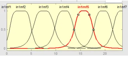
C. Fuzzy Controller Design with ANFIS
In this paper, by using of ANFIS inference, a fuzzy capacitive mode controller is presented for regulating alpha in capacitive mode. Membership function plot of controller capacitive mode is shown in Fig [5]. This fuzzy controller contains 15 rules that are:
If (input1 is in1mfi) then (output1 is out1mfi)
Fig. 4. Diagram of TCSC control system.
Fig. 5. Membership function plot of controller capacitive mode
IV. SIMULATION RESULTS
Simulation studies have been carried out for the test power system consists of a two-area four-machine power system which is shown in Fig. 6 to minimize the objective function and determining the parameters of power system stabilizers
(PSS) and TCSC controller. In this system, machines 1 and 2 form a coherent group, and machines 3 and 4 form the other coherent group. There are three tie lines connecting the two coherent areas. There are three tie lines connecting the two coherent areas. As shown in Fig. 6, TCSC is installed in one of these tie lines [1].
In the first case study it was assumed that reference impedance (Zref) is changed as follows: initially Zref is set at 1pu; at t=2.5s, Zref is decreased to 0.95pu; finally at t=5s Zref again is stabled at 0.95pu. The short circuit faults have been assumed to occur at t=5s and five circle.
system with a TCSC controlled by PI: in this situation the active and reactive power flow in this bus is saturated and (c) study system with a TCSC controlled by Fuzzy: in this situation, active power flow in bus 101 is shown in Fig. 9 and reactive power flow in this bus is shown in Fig. 10.
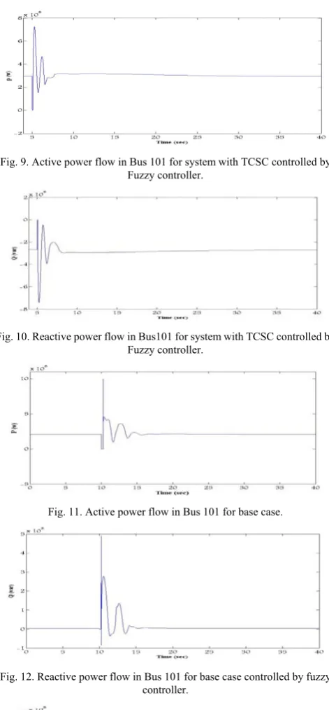
In the second case study, the settler power crossing Bus101 was considered as the reference. In this section the short circuit faults have been assumed to occur at t=10s and fifteen circle. By way of illustration, the performance of TCSC controller by PI was compared with the performance of TCSC controller by Fuzzy.
The results are classified in three groups. These groups are: (1) study system without any TCSC: in this situation, the active power flow in Bus 101 is shown in Fig.11 and the reactive power flow in this bus is shown in Fig. 12. (2) Study system with a TCSC controller by PI in which active and reactive power flow is saturated. Fig. 13 and Fig. 14 explain this fact. (3) Study system with a TCSC controller by Fuzzy where active power flow in Bus 101 is exhibited in Fig. 15 and reactive power flow is also shown in Fig. 16.
Fig. 6. TCSC in a two-area four-generator system.
Fig. 7. Active power flow in bus 101.
Fig. 8. Reactive power flow in bus 101.
Fig. 9. Active power flow in Bus 101 for system with TCSC controlled by Fuzzy controller.
Fig. 10. Reactive power flow in Bus101 for system with TCSC controlled by Fuzzy controller.
Fig. 11. Active power flow in Bus 101 for base case.
Fig. 12. Reactive power flow in Bus 101 for base case controlled by fuzzy controller.
Fig. 13. active power flow in Bus 3 for system with TCSC controlled by PI controller.
Fig. 15. Active power flow in Bus 3 for system with TCSC.
Fig. 16. Reactive power flow in Bus 3 for system with TCSC controlled by Fuzzy controller.
V.CONCLUSION
In this paper, the TCSC device was installed on transmission line. The controllers of TCSC were designed with two types: PI and fuzzy logic controllers. The performance of the two controllers was tested and compared. Results of simulation demonstrated that the effectiveness of the proposed fuzzy logic controller is far better than PI controllers. When a phase is cutout, PI controller cannot keep power stability but fuzzy controller can keep power stability. This ability is the advantage of using fuzzy controller and lead to improvement of power stability.
REFERENCES
[1] E. Larsen, K. Clark, S. Miske, and J. Urbanek J, “Characteristics and rating considerations of thyristor controlled series compensation,”
IEEE Trans. Power Deliv., vol. 9, no. 2, pp. 992-998, 1994.
[2] H. Ambriz-Pe´rez, E. Acha, and CR. Fuerte-Esquivel, “TCSC-firing angle model for optimal power flow solutions using Newton’s method,” Electrical Power and Energy Systems, vol. 28, pp. 77–85, 2006.
[3] D. Chatterjee and A. Ghosh, “TCSC control design for transient stability improvement of a multi-machine power system using trajectory sensitivity,” Electric Power Systems Research, vol. 77, pp. 470-483, 2007.
[4] ARM. Tenorio, N. Jenkins, and MHJ. Bollen, “A TCSC model for electromagnetic transient studies,” Proceedings of IEEE/KTH
stockholm power tech conference, Stockholm, 1995, pp. 5-130.
[5] KS. Hameed, B. Das, and V. Pant, “A self-tuning fuzzy PI controller for TCSC to improve power system stability,” Electric Power Systems
Research, pp. 1726–1735, 2008.
[6] CC. Lee, “Fuzzy logic in control systems: fuzzy logic controller-parts 1 and 2,” IEEE Trans. Systems Man and Cybernetics, vol. 20, no. 2, pp. 404-435, 1990.
[7] PK. Dash, S. Mishra, and AC. Liew, “Fuzzy-logic-based VAR stabilizer for power system control,” IEEE Proc. Generation
Transmission, vol. 42, no. 6, pp. 618-624, 1995.
[8] JSR. Jang, “ANFIS: Adaptive-Network-based Fuzzy Inference Systems,” IEEE Trans. Systems, Man, and Cybernetics, vol. 23, no. 3, pp. 665-685, 1993.
[9] L. Kirschner and GH. Thumm, “Studies for the Integration of a TCSC in a transmission system,” Proceedings of Singapore power system tech
conference; 2004.
[10] S. Brock, “Application of ANFIS controller for two - mass – system,”
ESIT, pp. 357-360, 2000.
[11] M. Kumar and DP. Garg, “Intelligent learning of fuzzy logic controllers via neural network and genetic algorithm,” Proceedings of
JUSFA, pp. 4-5, 2004.
[12] R. Billinton, M. Fotuhi-Firuzabad, and SO. Faried, “Power system reliability enhancement using thyristor controlled series capacitor,”
IEEE Trans. Power Syst., vol. 14, pp. 369-374, 1999.
Amir Zare was born in Shiraz, Iran. He received his
B.S. degree in Control Engineering from Shiraz University of Technology, Iran and currently studies Information and Automation Eng. in Bremen University, Germany.
Majid Nayeripour was born in Shiraz, Iran. He
received his B. S. degree in electronic Eng. from Guilan University and M.S degree in Electrical Eng. from Esfahan University of Technology and PhD degree in Electrical Eng. form Tarbiat Modares University, Tehran, Iran. Currently, he is an Associate Professor with the Shiraz University of Technology. His research interests include FACTS devices, Power Quality and impact of DGs on power system.
Xiaoning Kang was born in march 1968. He received
PhD in electrical Engineering from Xi'an Jiaotong University,China. Now he is associate professor in Xi'an Jiaotong University, China. His research interests include Renewable Energy, Distributed Generation, Smart Grids, Protection of power system and substation automation system.
Mostafa Kheshti was born in Noorabad Mamasani,
Iran in 1987. He received BSc Degree in Electrical Engineering from Shiraz University of Technology. He was technical expert of Fars Regional Electric Company and also published some papers and books. Currently he is Master Student in Xi'an Jiaotong University, China. His research interests include Renewable Energy, Distributed Generation, Smart Grids, Power System and Protection.
Taher Niknam was born in Shiraz, Iran. He received