MULTIFUNCTIONAL DYNAMIC VOLTAGE RESTORER
WITH PSO
Jyothi Zachariah, Asst.Prof.Jo Joy,Dept. of Electrical and Electronics,
Saintgits College of Engg.Kottayam
Abstract—Now a days power grid has been experiencing several
disturbances in electric power generation, transmission, and distribution. Changing electric load and higher power transfer in a wide interconnected network leads to serious, security lack in power system operation. As energy storage appears to be beneficial to utilities since it can co-ordinate the instantaneous balance between demand and supply. Today, there is a demand for short term energy storage devices like flywheel energy storage, photovoltaic modules, battery energy storage and super capacitors. Since they are having less power and energy rating, they cannot be used for high power applications. So in order to minimize this problem, SMES has been used to improve power system performance as well as power quality as it has having high power rating with maximum efficiency. Super conducting magnetic energy storage (SMES) based dynamic voltage restorer (DVR) is introduced to protect consumers from the grid voltage fluctuations. In normal DVR based compensation, downstream fault current was not considered or the DVR was bypassed during that fault. But here along with voltage sag compensation, downstream fault current mitigation was also considered. Using MATLAB, the SMES based DVR is modelled, and the simulation tests are carried out to evaluate the system performance. PI controller parameter adversely affects the dynamics of system stability like rise time,overshoot time and settling time.So its necessary for calculating the optimal value of PI controller parameters using any optimisation technique.Here its uses PSO algorithm for finding the optimal value.
Index Terms—Downstream fault, DVR, SMES, PSO,Power
Quality, Voltage Fluctuations
I.INTRODUCTION
As far as the equipments in world wide are taken into consideration, they are mostly electronic devices. They can be classified as programmable and non- programmble. But actually the problem arising is that whether it is programmable or non programmable they are very much sensitive to change in voltage or we can call it as fluctuations. Change in voltage can either be voltage sag or swell. From the previous studies it can be concluded that Voltage sags will be one of the most severe disturbance to the industrial devices. Compensation of these voltage can be done in different ways such as using shunt reactors, capacitors and by using different FACTS controllers. Shunt capacitors can be used in the primary side of the distribution transformer for the compensation of reactive power and thereby for voltage compensation. Using SCADA the mechanical switching can be done. There arises some drawbacks ie, high speed transients cannot be compensated. Some sags are not corrected within the limited time .Transformer taps can be used, but its costly when using on load.
Another solution existing to the voltage regulation is the use of a dynamic voltage restorer (DVR). The Dynamic Voltage Restorer (DVR) is a custom power device utilized to
counteract voltage sags. It injects controlled three-phase ac voltages in series with the supply voltage, subsequent to voltage sag, to enhance voltage quality by adjusting the voltage magnitude, wave shape , and phase angle.DVR operates in such a way that it injects a voltage corresponds to the fault level. The DVR are mainly used for sensitive loads that may be seriously affected by fluctuations in system voltage.
Voltage sags are becoming the most important power quality concern to electric utility customers with sensitive loads. Voltage magnitude between 0.1 to 0.9 Pu are said to be sags. As per the requirement, most of the utilities are interconnected. In such a way as the interconnection becomes complicated there induces severe fault and these dip in voltages are called voltage sags. The dynamic voltage restorer (DVR) is a series connected power electronics device which can compensate for both voltage sag and swell. Its primary function is to rapidly boost up the load side voltage in the case of a disturbance in order to avoid any power disruption to that load [7]. By using appropriate controllers it can also be used for downstream fault current mitigation. DVR is commonly meant for compensating fault that occurred in between the source and the DVR. In normal DVR based compensation, downstream fault current was not considered or the DVR was bypassed during that fault.Downstream fault current means the fault occurring in between DVR and load side. Here a controller is proposed for downstream fault current mitigation. So here a complete compensation of a transmission line is proposed. Different energy storage devices can be used along with DVR in order to increase its compensation capability. Here a superconducting magnetic energy storage device is used. A Superconducting Magnetic Energy Storage device consists power electronic converters that rapidly injects and/or absorbs real and/or reactive power and thereby controls power flow in an distribuition / transmission system. [2][5][7] PI controller parameter adversely affects the dynamics of system stability like rise time,overshoot time and settling time.So its necessary for calculating the optimal value of PI controller parameters using any optimisation technique..Here its uses PSO algorithm for finding the optimal value.
II.MODELLING OF THE DVR
INTERNATONAL JOURNAL OF INNOVATIVE RESEARCH IN TECHNOLOGY DVR can also compensate for line voltage harmonics
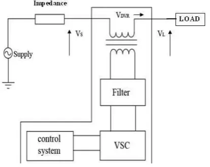
,reduction of transients in voltage and fault current limitations. A.Basic Configuration of DVR
The main components of the DVR consists of:
Energy storage unit
Filter unit
Inverter circuit
Series injection transformer
Energy storage unit
Whenever a fault occur, DVR needs to supply a voltage inorder to compensate for that voltage. So that it needs an energy storage device to supply that amount. We can either use stored energy or we can use energy directly from supply. Inverter circuit
The incoming supply from an energy source is dc. So inorder to transmit it to the transmission line, there is a requirement of a inverter. Here it uses a voltage source converter to convert that dc voltage to ac.
Filter unit
Mostly all of the semiconductor devices consists of non linear characteristics. Non linear characteristics causes distorted waveforms that contain harmonics. So inorder to avoid that disturbance at the end here it uses a filter unit so that the output is purely sinusoidal. Filter unit is an urgent requirement of a dynamic voltage restorer.
Series injection transformer
Whenever a fault occur, DVR needs to supply a voltage inorder to compensate for that voltage. That voltage must be injected through a series injection transformer. Series injection transformer means transformer windings are connected in series.
Fig. 1 Components of DVR
B.Mathematical model of DVR
Fig. 2 Equivalent Circuit of DVR
Fig 2 shows the equivalent circuit of DVR.The series injected voltage of the DVR can be written as
The complex power injection of the DVR can be written as,
The load current IL is given by,
III.SUPERCONDUCTING MAGNETIC ENERGY STORAGE(SMES)
Superconducting MagneticEnergyStorage (SMES) systems store energy in the magnetic field created by the flow of direct current in a superconducting coil. An SMES system consists of three parts: a superconducting coil, power conditioning system and a cryogenically cooled refrigerator.
Once the superconducting coil is charged, the current will not decay and the magnetic energy can be stored indefinitely. This is the main property of SMES.
currently used for short duration energy storage. Therefore, SMES is most commonly meant to improve power quality.
Fig. 3 Schematic diagram of SMES
The magnetic energy stored by a coil of an SMES is given by
(6)
Fig. 4 Schematic diagram of SMES based DVR
IV.CONTROL CIRCUIT
In normal DVR based compensation, downstream fault current was not considered or the DVR was bypassed during that fault. But here along with voltage sag compensation downstream fault current mitigation was also considered. The control scheme for the mitigation of downstream fault current is given below.
Fig. 5 Control block diagram of mitigation of fault current The DVR is conventionally bypassed during a downstream fault to prevent potential adverse impacts on the fault and to protect the DVR components against the fault current. A
technically elaborate approach to more efficient utilization of the DVR is to equip it with additional controls and enable it also to limit or interrupt the downstream fault currents. A control approach to enable a DVR to serve as a fault current limiter is proposed earlier .The main drawback of this approach is that the dc-link voltage of the DVR increases due to real power absorption during fault current-limiting operation and necessitates a switch to bypass the DVR when the protective relays, depending on the fault conditions, do not rapidly clear the fault.
The proposed DVR is a multifunctional DVR that is it can mitigate for both voltage sag and downstream fault current . Thus, the mutual effects of these modes on each other must be evaluated. At 15 ms, the system is subjected to a phase-A to phase-B fault with the resistance of 0.8 ohm at 90% of the line length from source side. The fault causes 87% voltage sag at the PCC. At 55 ms, another fault with the resistance of 0.3 on phase-A at 10% length of the cable at load side.
The system is subjected to a three-phase short circuit with a negligible fault resistance at 0.2 ms . Prior to the fault inception, the DVR is inactive (in standby mode) (i.e., the primary windings of the series transformers are shorted by the DVR). During the fault if the DVR is bypassed, the voltage at VI Measurement 1 drops to 0.77 p.u. and the fault current increases to about 17 times the rated load current . Fig. 11 shows the performance of the proposed DVR control system during the fault. Fig. 11 illustrates that the proposed FCI method limits the maximum fault current to about 2.5 times the nominal value of the load current and interrupts the fault currents in less than 1 cycles.
V.PARTICLE SWARM OPTIMISATION
INTERNATONAL JOURNAL OF INNOVATIVE RESEARCH IN TECHNOLOGY optimization problems. The PSO technique can generate a
high-quality solution within shorter calculation time and stable convergence characteristic than other stochastic methods.[25] Particle Swarm Optimization (PSO) is a technique used to explore the search space of a given problem to find the settings or parameters required to maximize a particular objective. This technique, first described by James Kennedy and Russell C. Eberhart in 1995, originates from two separate concepts: the idea of swarm intelligence based off the observation of swarming habits by certain kinds of animals (such as birds and fish); and the field of evolutionary computation.The PSO algorithm works by simultaneously maintaining several candidate solutions in the search space. During each iteration of the algorithm, each candidate solution is evaluated by the objective function being optimized, determining the fitness of that solution. Each candidate solution can be thought of as a particle flying through the fitness landscape finding the maximum or minimum of the objective function. Initially,the PSO algorithm chooses candidate solutions randomly within the search space. The search space is composed of all the possible solutions along the x-axis; the curve denotes the objective function. It should be noted that the PSO algorithm has no knowledge of the underlying objective function, and thus has no way of knowing if any of the candidate solutions are near to or far away. Each particle maintains its position, composed of the candidate solution and its evaluated fitness, and its velocity. Additionally, it remembers the best fitness value it has achieved thus far during the operation of the algorithm, referred to as the individual best fitness, and the candidate solution that achieved this fitness, referred to as the individual best position or individual best candidate solution. Finally, the PSO algorithm maintains the best fitness value achieved among all particles in the swarm, called the global best fitness, and the candidatesolution that achieved this fitness, called the global best position or global best candidate solution.
VI.SIMULINK MODEL AND RESULTS
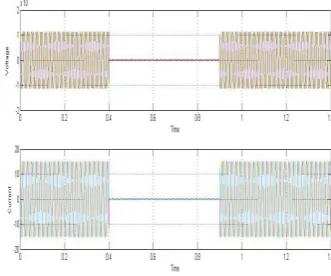
Using MATLAB, the model of DVR is established, and the simulation tests are conducted. A fault is given for a period of 0.4-0.8s. At 0.5s the circuit breaker gets opened and closes on 0.9s. Without using DVR, from the fig. it is clear that, when a fault is applied voltage gets reduced. With DVR when the circuit breaker gets opened, DVR is automatically connected and injects appropriate voltage in proportion to the reduction in voltage and hence get compensated.
Fig. 6 SMES based DVR
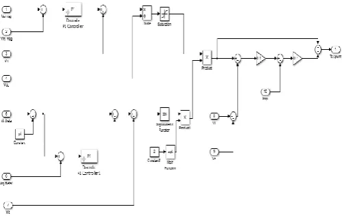
Fig.7 Detailed SMES model
Fig shows the basic configuration of the VSC-based SMES unit, which consists of a Wye-Delta transformer, a six-pulse pulse width modulation (PWM) rectifier/inverter using insulated gate bipolar transistor (IGBT), a two-quadrant dc-dc chopper using IGBT, and a superconducting coil or inductor. The PWM converter and the dc-dc chopper are linked by a dc link capacitor. The PWM VSC provides a power electronic interface between the ac power system and the superconducting coil.
Fig. 8 Simulation results without DVR
Fig. 9 Simulation results with SMES based DVR
Fig.11 With normal PI controller
Fig.12. With PSO based PI controller
From the above fig it can be seen that with PSO based PI controller the settling time ismuch improved when compared to normal PI controller.In fig.11 normal PI controller,the settling time taken is 0.06s ie from 0.8 to 0.86s and in fig 12 with PSO based PI controller, the settling time is reduced to 0.025s ie from 0.8 to 0.825s.
Fig.13 Downstream Fault current mitigation Fig.13 illustrates that the proposed FCI method limits the maximum fault current to about 2.5 times the nominal value of the load current and interrupts the fault currents in less than1 cycles.
VII.CONCLUSION
Due to the characteristic of high energy density and quick response, a superconducting magnet is selected as the energy storage unit to improve the compensation capability of DVR. In addition to that, an auxiliary control strategy for the
interruption of downstream fault current in transmission line is introduced. By the use of a PSO based PI controller,the settling time is reduced to 0.025s when compared to normal PI controller.Further development is expected for increasing the compensation time in a cost effective manner.Compensation time can be extended from second to hours by increasing the value of inductance.Using a high temperature superconducting coil in practical applications can reduce the cost to an extend..
REFERENCES
[1]. Jing Shi ; R&D Center of Appl. Supercond., Huazhong Univ. of Sci. & Technol.,Wuhan, China ; Yuejin Tang ; Kai Yang ; Lei Chen “SMES Based Dynamic Voltage Restorer for Voltage Fluctuations Compensation in Applied Superconductivity, IEEE Transactions on (Volume:20 , Issue: 3 )June 2010
[2] S. Deepa1, Mrs. K. Esakki shenbagaloga Fx-Engineering College,Thirunelveli “Voltage Sag Mitigation In LV And HV Platform Using Smes Based DVR” International Journal of Renewable Energy Technology Research Vol. 2, No. 4, April 2013
[3]. Kadam, P.S. ; Dept. of Electr. Eng., Dr. B.ATechnol.Univ.,Raigad,India; Vadirajacharya, K.”Super conducting magnetic energy storage based DVR” In Electrical, Electronics and Computer Science (SCEECS), 2012 IEEE Students'Conference on Date of Conference: 1-2 March 2012
[4]. H.P. Tiwari and Sunil Kumar Gupta “Dc Energy Storage Schemes For DVR Voltage Sag Mitigation System” International Journal of Computer Theory and Engineering, Vol. 2, No. 3, June, 2010
[5].T.Saravanan, M. Sundar Raj and K.Gopalakrishnan Department of ETC, Bharath University, Chennai, India “SMES Technology, SMES and Facts System, Applications, Advantages and Technical Limitations”Middle-East Journal of Scientific Research 2011: 1353-1358
[6]. Mahdianpoor, F.M. ; Dept. of Electr. Eng., Univ. of Isfahan, Isfahan, Iran ; Hooshmand, R.A. ; Ataei, Mohammad “A New Approach to Multifunctional Dynamic Voltage Restorer Implementation for Emergency Control in Distribution System in Power Delivery, IEEE Transactions on (Volume:26 , Issue: 2 April 2011
[7.] ANJU M PG Scholar, Department of EEE SNS College of Technology Coimbatore “Co-Ordination Of SMES With Statcom For Mitigating SSR And Damping Power System Oscillations In A Series Compensated Wind Power System”International Conference on Computer Communication and Informatics (ICCCI -2013)
[8] Subhojith Malik;”Parameter estimation of a PID controller using Particle Swarm Optimisation”,International Journal of Advanced research in computer and communication engineering,Vol.3 March 2014.
[9] Zwe-Lee Gaing, Member ”A Particle Swarm Optimization Approach for Optimum Design of PID Controller in AVR System in IEEE transactions on Energy Conservation” VOL. 19, NO. 2, JUNE 2004