Gear Test Rig - A Review
A. P. Arun*
1, A.P.Senthil kumar
2, B. Giriraj
3, A. Faizur rahaman
41Department of Mechanical Engineering, Kumaraguru College of Technology, Coimbatore - 641049, India.
2,3Department of Mechanical Engineering, PSG College of Technology, Coimbatore-641004, India. [email protected]
4Department of Mechanical Engineering, CSI College of Engineering, Nilgiris-643215, India.
Abstract-- In the past decades, many impressive progress had been made in the field of simulation and analysis, even though experiments are necessary in many fields to conduct investigation on mechanical components [26]. Gears are one of the such components that needed to be tested experimentally. Therefore, test rigs are required with the possibility of varying speed and torque during the test, based on the requirement. In this paper, development of test rigs for evaluating the performance of gear has been studied. The main objective of this paper is to give researchers an idea about the physical development of a gear test rig. Test rig developed by various researchers based on the parameters to be tested were discussed with schematic representation and test procedure. A new gear test rig also fabricated by the authors and development procedure of the same was discussed.
Index Term— gear testing machine, FZG test rig, Back-to-back gear test rig, simple gear test rig.
I. INTRODUCTION
Power transmitted by Gear boxes were fluctuating strongly in many of the applications. For example, in automobiles, based on the condition of driving, torque and speed varies. In machining operations, based on the material to be machined, torque and speed varies. These evidences show that, test rigs are needed for testing such gear boxes. Performance of gears depends on parameters like its design, material, manufacturing and working environment. Developing a mathematical model to predict the life of gear will be difficult because of interaction between these parameters [1-7]. Therefore a separate test rig is needed for predicting the life of the gears. Sometimes noise from the gearbox becomes a dominating one this creates a bad impression over the gear quality. To overcome this noise from the gear to be reduced 10–15 dB compared with other noise sources like engine noise. So gears to be tested for noise under controlled environment [8, 9]. Other than that when the gear pair exceeds its load carrying capacity different modes of failure will occur like, micro-pitting, pitting, tooth breakage, scuffing, excessive wear, etc. other parameters like the gear‟ s dynamic behavior and its efficiency also to be investigated
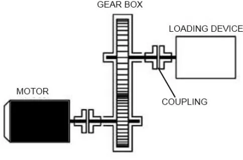
gears under controlled environment is needed. A simple construction of a test rig is shown in Fig. 1 which consists of a prime mover (motor), loading device (brake, dynamo meter, pump, etc.) and the test gear box which is to be mounted between the prime mover and loading device.
Fig. 1. Simple construction of a gear test rig
II. GEAR TEST RIG FOR MEASURING VARIOUS
PARAMETERS
A. Noise Testing
microphone is located close to the tooth mesh. The microphone was located close to the tooth mesh and acceleration sensors are mounted near the bearing. Fig.3. shows the schematic representation of the test rig used for this investigation.Åkerblom M [25] uses a Mechanical power recirculation type test rig. Were two identical gear boxes were connected through a universal joint as shown in Fig.4. One of the gear boxes was tilted with the aid of hydraulic cylinder for applying load. Accelerometers were mounted on the gearbox
for vibration measurement. Microphones were used to measure the noise. The total setup was mounted over a concrete stage. To conduct investigation on the resonance frequency behavior of spur gears Shuting Li [20] used a power circulating test rig was used. Rubber couplings were used to avoid the effect of vibration signals from motor and shaft. Construction of this test rig is shown in Fig.5.
Fig. 2. Test rig for investigating gear noise emission [10]
Fig. 4. Test rig for vibration measurement [25]
Fig. 5. Test rig to investigate the resonance frequency [20]
B. Lubricant viscosity and additives
T. L. Krantz et al [12] investigates the influence of lubricant viscosity and additives on gear wear, speed of the motor was
a separate system. 55 μm fiberglass filter was used to remove wear particles, for each test 3.8 liters of lubricant was used. A vibration transducer is used to stop the test rig if fatigue damage occurred over the gear surface. The schematic representation of test rig used in this investigation is shown in Fig.6.
To understand the effect of lubricant contamination on gear wear Mohamed Rafik Sari et al [15] used the test rig as shown in Fig.7, to conduct the test pinion was rotated at 200 RPM with a load of 265 N applied by a hydraulic control system. Lubricating oil was supplied by a gravity feed system so is to maintain constant meniscus of liquid in the contact area of gears.
Fig. 7. Test rig to investigate the effect of lubricant contamination on gear wear [15]
C. Strength of the Gear
Qi Zhang, et al [13] evaluates contact fatigue strength of the gear, for that motor speed of 1440 RPM was maintained with 1000 Nm. Load clutch is carried by front shaft which is used to apply the load. The flanges of the load clutch are twisted relative to each other and bolted together for applying load. Torque was applied by weights and load lever. Dip lubrication of 85W/90 GL-5 type heavy-duty automobile gear oil was used and the temperature of lubricating oil was maintained
constantly by the application of heating and cooling coil. Test rig used for this work is shown in Fig. 8. To know the contact fatigue performance of the gear V. Moorthy et al [16] used the test rig as shown in Fig. 9 input speed of 3000 RPM was maintained with two different torque levels of 460 NM and 570 NM. Aeroshell oil at 100 ◦C was used as lubricating oil. Identification of progressive contact fatigue damage was analyzed by tooth profile measurement at each stage.
Fig. 9. Test rig to evaluate contact fatigue performance of the gear [16]
D. GEAR FAILURE INVESTIGATION
For monitoring distributed pitting failure in gears Hasan Ozturk et al [17] used the test rig as shown in Fig. 10. Speed range of 0 to 3000 RPM. Stiffened structure was used to mount Motor and gear box. Two PCB 352A76 type accelerometer was used to detect vibration signal produced by the gears. For determining the resistance to scuffing W. Tuszynskin et al [19] used FZG T-12U type test rig whose schematic representation is shown in Fig.11, an AC Squirrel cage motor makes the input shaft to run at 3000 RPM. A mass comparator was used to measure the wear rate of the gear.K. Mao [21] designed polymer composite gear and he developed
a test rig for wear measurement as shown in Fig.12. where the movement of the bearing block was recorded using capacitive transducer of non contact type in order to measure gear wear. R. Yakut et al [23] et al, uses a FZG test rig as shown in Fig.13. for finding the load capacity of PC/ABS spur gears and to investigate gear damage. Load range chosen was 16.07, 20.5 and 29.36, rotational speed range was 750, 1000 and 1500. Pitch line velocity (m/s) taken as 3.57, 4.76 and 7.14. DC electric motor of 7.5 KW is used for producing input power. Weight loss measured with 0.0001sensitivity weighing machine. The mean temperature of gear tooth was measured with impact infratherm pyrometer 510-N at a distance of 7mm from the gear meshing point.
Fig. 11. Test rig for determining the resistance to scuffing [19]
Fig. 13. Test rig for finding the load capacity [23]
E. GEAR EFFICIENCY AND PERFORMANCE
Seong Han Kim et al, [18] predicted efficiency of the plastic worm wheel, input torque was applied by a servo motor and resistant torque was applied by a power brake. Torque range of 2 Nm to 60 Nm with angular speed range of 30 deg/s to 360 deg/s was chosen for conducting the tests. Physical arrangement of the test rig is shown in Fig. 14. To understand the performance of glass fiber reinforced nylon 6 spur gear based on the rotational speed, S. Senthilvelan, and R. Gnanamoorthy [22] developed a power absorption test rig and its schematic representation is shown in Fig.15. and they followed the following procedure to test its performance. Testing of gears were done at torque levels of 0.8, 1.5, 2, 2.5 and 3 Nm., Lewis equation was used to compute bending stress on gear tooth. 600, 800, 1000 and 1200 RPM is the gear rotational speeds used to conduct tests. Testing of gears were
Fig. 14. Test rig for predicting efficiency of the gear [18]
Fig. 15.Schematic of the power absorption gear test rig [22]
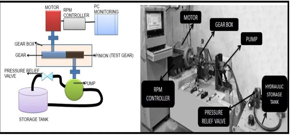
F. DEVELOPMENT OF SIMPLE GEAR TEST RIG WITH PUMP AS LOADING DEVICE
Concrete basement was created for placing the frame. The Frame was bolted to the basement. Motor, brackets for holding gear box and pump were placed over the frame. 3 Φ
50HP AC induction motor provides input power. Loading of gear is done by a gear pump with hydraulic system. Schematic arrange of the test rig is shown in Fig. 17.
Fig. 17. gear test rig with pump as loading device
A separate RPM controller is used to control the speed of the motor within the range of 0 to 3000 RPM. Flange couplings are used to connect the motor shaft with gearbox input shaft and gearbox output shaft with pump shaft. Eccentricity is avoided with the help of dial gauge while connecting with flange coupling. Gear loading is done by adjusting the pressure relief valve mounted between pump output and storage tank. 0 to 700 bar pressure can be applied as a load to the gear. Vibration meter with 10 to 1 kHz frequency range is used to measure the acceleration level of the gearbox. Decibel meter with 30 to 130 dB is used for measuring noise level of the gear box. A J type thermocouple is used to measure the gearbox oil temperature and infrared thermometer with a range of -30 to 3050C is used to find the gear tooth temperature, for that a separate hole is produced in the gearbox above the tooth contact area.
CONCLUSION
Various kinds of gear test rigs developed by various authors were discussed in this paper. Based on the review a new test rig was also developed with available equipments inside the laboratories and the data acquired from the test rig is more reliable. The developed test rig is ready for conducting
research on gears. This paper will be more useful for researchers in the field of gears. Based on the parameters to measure and the test procedure, researchers can develop their own gear test rig.
REFERENCE
[1] B.J.Roylance, A.M.Koroma, J.Vizintin, I.Libuscek, “Tribological considerations in the operation monitoring, and maintenance of gear transmission systems”, Proc of the Intl Gearing Conf, Newcastle upon Tyne, U.K, pp 453-457,1994.
[2] C.Madhavan, “Effects of heat treatments on the surface durability of ferrous based powder metal spur gears”, PhD thesis, IIT Madras, 1991.
[3] T.L.Krntz, M.P.Alanou, H.P.Evans and R.W.Snidle, “Surface fatigue lives of case carburised gears with an Improved surface finish”, J of Tribology, Vol 123,pp 709- 716,Oct, 2001.
[4] Damodar Reddy, “Oil film thickness measurements in spur gears in re-circulating test gear”, M. Tech Thesis, IT Madras 1972. [5] M.Kato, k. Inoue, Shibata and H.Zhou,” Evaluation of the sound
power radiated by a gearbox”, Proc of the Intl Gearing conf, Newcastle upon Tyne, UK, pp. 69-74,1994.
[6] D.J.Fessett,”How to Test Gear Transmissions”, Machine Design, Vol47, No 18, pp 61-64, July 24, 1975.
[7] D.J.Fessett, “Hardware for Testing Gear Transmissions”, Machine Design, Vol 47, No 19, pp 80-83, August 7, 1975.
[8] Hellinger W., Raffel H. Ch., Rainer G. Ph., Numerical Methods to Calculate Gear Tranmission Noise, SAE Technical Paper 971965, 1997.
[10] Essam Allam, Ibrahim Ahmed and Shawki Abouel-Seoud, “An experimental investigation of noise emission from a vehicle gearbox system” Journal of Mechanical Engineering Research
Vol. 3(3), pp. 75-84, March 2011
[11] Hui Li1 ,Yuping Zhang and Haiqi Zheng, “Gear fault detection and diagnosis under speed-up condition basedon order cepstrum and radial basis function neural network” Journal of Mechanical Science and Technology, Vol. 23, pp. 2780~2789, 2009. [12] T. L. Krantz, A. Kahraman, “An Experimental Investigation of the
Influenceof the Lubricant Viscosity and Additives on Gear Wear”
Tribology Transactions, Vol. 47, pp. 138-148, 2004
[13] Qi Zhang, Jing Zhang, Changhong Wu, Zhezhu Xu and SungKi Lyu, “The Evaluation of Contact Fatigue Strength for 20MnCr5 Carburized Gear” International Journal Of Precision Engineering And Manufacturing Vol. 15, No. 1, pp. 117-121
[14] Brecher, C. Gorgels, C. Carl and M. Brumm, “Benefit of Psychoacoustic Analyzing Methods for Gear Noise Investigation”
Gear Technology, pp. 49-55,August 2011.
[15] Mohamed Rafik Sari, Ammar Haiahem, “Effect of Lubricant Contamination on Gear Wear” Tribol Lett , Vol. 27:119–126 ,2007
[16] V. Moorthy, B.A. Shaw, “Contact fatigue performance of helical gears with surface coatings” Wear , Vol. 276– 277 ,130– 140, 2012
[17] Hasan Ozturk , Isa Yesilyurt and Mustafa Sabuncu, “Detection and Advancement Monitoring of Distributed Pitting Failure in Gears” J Nondestruct Eval , Vol. 29, pp. 63–73, 2010
[18] Seong Han Kim, Min Chul Shin, Jung Won Byun, Kwang Hwan O and Chong Nam Chu, “Efficiency Prediction of Worm Gear with Plastic Worm Wheel” International Journal of Precision Engineering and Manufacturing, Vol. 13, No. 2, pp. 167-174 [19] W.Tuszynskin, R.Michalczewski,M.Szczerek,M.Kalbarczyk, “A
new scuffing shock test method for the determination of the resistance to scuffing of coated gears” Archives Of Civil And Mechanical Engineering, Vol. 12 , pp. 436 – 445, 2012.
[20] Shuting Li, “Experimental investigation and FEM analysis of resonance frequency behavior of three-dimensional, thin-walled spur gears with a power-circulating test rig” Mechanism and Machine Theory , Vol. 43, pp. 934–963, 2008.
[21] K. Mao, “A new approach for polymer composite gear design”
Wear , Vol. 262, pp. 432–44,2007.
[22] S. Senthilvelan, R. Gnanamoorthy, “Effect of rotational speed on the performance of unreinforced and glass fiber reinforced Nylon 6 spur gears” Materials and Design , Vol. 28, pp. 765–772, 2007. [23] R. Yakut, H. Düzcükoğlu, M.T. Demirci, “The load capacity of
PC/ABS spur gears and investigation of gear damage” Archives of Materials Science and Engineering, Vol. 40-1, pp. 41-46, 2009. [24] T. T. Petry-Johnson A. Kahraman , N. E. Anderson, D. R. Chase,
“An Experimental Investigation of Spur Gear Efficiency” Journal of Mechanical Design , Vol. 130, Pp 062601-1 to 7, JUNE 2008, [25] Åkerblom M. „Gear Test Rig for Noise and Vibration Testing of
Cylindrical Gears‟, Proceedings OST-99 Symposium on Machine Design, Stockholm, pp. 183–189, 1999.
![Fig. 2. Test rig for investigating gear noise emission [10]](https://thumb-us.123doks.com/thumbv2/123dok_us/1363855.1645774/2.612.88.536.406.608/fig-test-rig-investigating-gear-noise-emission.webp)
![Fig. 5. Test rig to investigate the resonance frequency [20]](https://thumb-us.123doks.com/thumbv2/123dok_us/1363855.1645774/3.612.71.540.75.311/fig-test-rig-investigate-resonance-frequency.webp)
![Fig. 7. Test rig to investigate the effect of lubricant contamination on gear wear [15]](https://thumb-us.123doks.com/thumbv2/123dok_us/1363855.1645774/5.612.182.431.432.664/fig-test-investigate-effect-lubricant-contamination-gear-wear.webp)
![Fig. 9. Test rig to evaluate contact fatigue performance of the gear [16]a test rig for wear measurement as shown in Fig.12](https://thumb-us.123doks.com/thumbv2/123dok_us/1363855.1645774/6.612.152.461.59.306/fig-test-evaluate-contact-fatigue-performance-measurement-shown.webp)
![Fig. 11. Test rig for determining the resistance to scuffing [19]](https://thumb-us.123doks.com/thumbv2/123dok_us/1363855.1645774/7.612.85.531.405.659/fig-test-rig-determining-resistance-scuffing.webp)
![Fig. 13. Test rig for finding the load capacity [23]](https://thumb-us.123doks.com/thumbv2/123dok_us/1363855.1645774/8.612.171.449.63.255/fig-test-rig-finding-load-capacity.webp)
![Fig. 14. Test rig for predicting efficiency of the gear [18]](https://thumb-us.123doks.com/thumbv2/123dok_us/1363855.1645774/9.612.160.452.530.682/fig-test-rig-predicting-efficiency-gear.webp)