Abstract— A study of the effect of different shapes of corrugated beds on the characteristics of hydraulic jumps was conducted. Experiments were performed for a range of the Froude number from 3 to 7.5. Five shapes of corrugations (sinusoidal, triangular, trapezoidal with two side slopes and rectangular) of the same amplitude and wavelength were tested. Two values of relative roughness t/y1 of 0.36 and 0.72 were studied. It was found that, for all shapes of corrugated beds, the tailwater depth required to form a jump was appreciably smaller than that for the corresponding jumps on smooth beds. Further, the length of the jump on the different corrugated beds was less than half of that on smooth beds. The integrated bed shear stress on the corrugated beds was more than 15 times that on smooth beds. For the same amplitude and wavelength, it was found that the effect of the shape of corrugations is relatively small. The results of this study confirm the effectiveness of corrugated beds for energy dissipation below hydraulic structures.
Index Term-- Corrugated Beds, Energy dissipation,, Hydraulic jump, Open channel flow.
I. INT RODUCT ION
Hydraulic jumps have been widely used for energy dissipation below hydraulic structures. In hydraulic-jump-type energy dissipators, the jumps are often formed with the assistance of baffle blocks and are kept inside the stilling basin even when the tailwater depth is somewhat less than the sequ ent depth of the free jump [1]. A jump formed in a horizontal, wide rectangular channel with a smooth bed is often referred to as the classic hydraulic jump and has been studied extensively [1], [2], [3], and [4]. If y1 and U1are, respectively, the depth and mean velocity of the supercritical stream just upstream of the jump, with a Froude number of F1=U1/(gy1)
0.5where g is the acceleration due to gravity, the subcritical sequent depth y2*is given bythe well- knownBelanger equation
y*2/y11/2[ 18F12 1] (1)
1Assistant Professor, Civil Engineering Department, King Saud
University, Riyadh, KSA; phone: 0049501214635; fax: +49014677008; e-mail: elsebaie@ksu.edu.sa
2
Associate Professor, Department of Civil Engineering, Ain Shams University, Cairo, Egypt
A preliminary investigation by [5] indicated that, if the bed of the channel on which the jump is formed is rough, the tailwater depth y2 required to form a jump could be appreciably smaller than the corresponding sequent depth y2*. For a relative roughness of the bed in terms of the supercritical depth y1 equal to about 0.4, y2 could be as small as 0.8y2*, which is significant when it is realized that the tailwater depth required for Peterka’s Basins II and III in terms of y2*are approximately 0.83 and 0.97, respectively. Further studies by [6], [7] and others (see [4]) have supported this reduction in the required tailwater depth produced by the roughness of the bed. Further, [5] found that the jumps on rough beds were significantly shorter than the classical jump.
Reference [8] performed a laboratory study of hydraulic jumps on corrugated beds for a range of Froude numbers from 4 to 10 and three values of the relative roughness t/y1 from 0.25 to 0.50. Reference [8] found that the ratio y2/y1 of the tailwater depth to the supercritical depth needed to form a jump for any Froude number was noticeably smaller than that for the corresponding jump on a smooth bed. Reference [8] explained that the reason for the reduction of the jump –forming tailwater depth appeared to be the enhanced bed shear stresses produced by the interaction of the supercritical stream with the bed corrugations. Reference [8] added that the bed shear stress on corrugated beds was about ten times that on smooth beds. Reference [9] conducted an experimental study to investigate the effect of trapezoidal shaped corrugated beds on the characteristics of hydraulic jump. They confirmed the results of reference [8]. Reference [9] added that the jump length is more dependent on the wave length of corrugations than their amplitude.
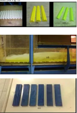
2. EXPRIM ENTAL SETUP AND PROCEDURE A. Hydraulic jumps were produced in a Rectangular flume 29.5 cm wide, 32.0 cm deep and 9.0 m long. The side walls of the flume were made of transparent Plexiglas sheets.Water was pumped from a storage tank to the head tank of the flume by a centrifugal pump. Corrugated plastic sinusoidal sheets and corrugated wooden triangular, rectangular and trapezoidal sheets (see Fig. 1(a-e)) were installed on the flume bed in such a way that the crests of corrugations were at the same level as the upstream bed on which the supercritical stream was produced by a sluice gate. The corrugations acted as depressions in the bed, to create a system of turbulent eddies
Formation Of Hydraulic Jumps On Corrugated
Beds
which might increase the bed shear stresses. All the five types of corrugations (I, II, III, IV and V) had a wavelength s of 65 mm in the flow direction and an amplitude t of 18 mm. One of the two trapezoidal sections and the triangular section had side slopes of 45 degrees. The other trapezoidal section had side slopes of 60 degrees. The discharges were measured by a V-notch installed in a measuring tank located at the end of the flume. Water entered the flume under a sluice gate with a streamlined lip, thereby producing a uniform s upercritical stream with a thickness of y1. A tailgate was used to control the tailwater depth in the flume. In all the experiments, the tailgate was adjusted so that the jumps were formed on the corrugated beds (see Fig. 2).
Fig. 1. (a) Sinusoidal; (b) T rapezoidal (45o side slopes); (c) T riangular; (d) T rapezoidal (60o side slopes); and (e) Rectangular Corrugations
A total of 55 experiments (11 for every sheet) were conducted and the primary details of these experiments are shown in table I. For all the five sheets six experiments of series A and five experiments of series B were conducted. The initial depth y1, measured above the crest level of corrugations on t he plane bed, was equal to 25 mm in the A series and 50 mm in the B series. Values of y1 and V1 were selected to achieve a wide
range of the Froude number, from 3 to 7.5. The Reynolds number R1=V1y1/υ was in the range of 49,523-142,157. Two values of the relative roughness, defined as the ratio of the amplitude of the corrugations to the supercritical depth just before the jump, t/y1 of 0.36 and 0.72 were investigated.
x y
Bed Head
Corrugated
y
yt
Lj= Jump Lrj= Roller
t
s
Fig. 2. Definition sketch for free jumps on corrugated beds (sheet II)
3. EXPERIM ENTAL RESULTS AND ANALYSIS
3.1 WATER SURFACE PROFILES
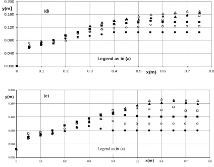
Figs. 3(a-e) show the water surface profiles for the A series experiments of the jumps on the five corrugated sheets , respectively. These profiles were measured in the vertical centerplane of the flume with, a point gauge to an accuracy of 0.1 mm. These water surface profiles were used to determine the subcritical sequent depth y2 at the end of the jump, which was defined as the section beyond which the water surface was essentially horizontal, and the length of the jump Lj. Normalized water surface profiles are shown in Figs. 4(a-e) where (y-y1)/(y2-y1) is plotted against x/Lj, with y the depth of flow at any station x. Figs . 4(a-e) show that the water surface profiles, for each type of corrugated beds, are approximately similar and can be represented by one mean curve.
3.2 SEQUENT DEPTH RATIO
For a jump on a corrugated bed of corrugation amplitude t, with a supercritical stream of depth y1 and mean velocity V1, the depth at the end of the jump y2 may be written as
y2 = f1(y1, U1, g, ρ, υ, t, ) (2) Where ρ = mass density and ν = kinematic viscosity of the fluid, represents the shape of the corrugated bed. Using the Pi theorem, it can be shown that
y2/y1 = f2 (F1=U1/(gy1) 0.5
, R1= U1y1/υ, t/y1, ) (3) For large values of the Reynolds number (involved in this study), viscous effects may be neglected (see [10] and [11]) and (3) reduces to
y2/y1 = f3 ( F1, t/y1, ) (4) The experimental results are shown in Fig. 5 with y2/y1 plotted against F1 for series A (t/y1 = 0.72) and series B (t/y1 = 0.36) for the five types of corrugated beds . Eq. 1 (Belanger Equation) is also shown in Fig. 5. It can be seen from Fig. 5 that the relative roughness and shape of corrugations do not have
(a) (b) (c)
significant effects on the depth ratio. It was also found that the depth ratio y2/y1 is approximately equal to 88% of the supercritical Froude number F1. Hence, (4) could be written as
y2/y1 = 0.88F1 (r 2
=0.94) (5) Since the corrugations were set with their crests at the upstream bed level, the corrugation acted like cavities and the t/y1, values were not important. In the experiments conducted by [5], with protruding roughness elements, the relative roughness height was an importantparameter. For relatively large values of the Froude number F1, the sequent depthratio for the classical jump can be written as
1 1 2 * 2
2
1
2
F
F
y
y
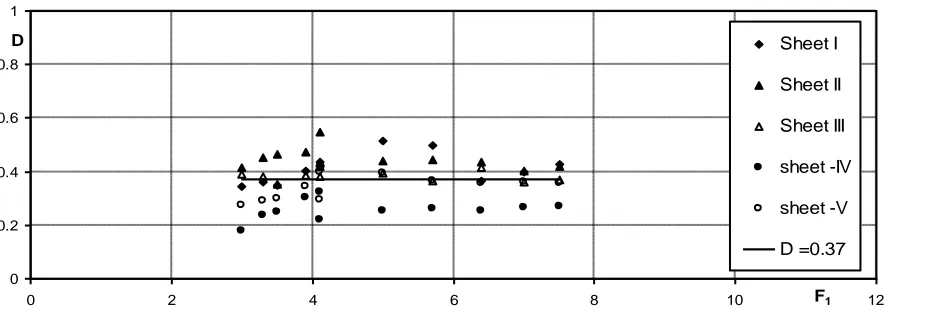
(6)To get an appreciation for the reduction in the tailwater depth y2 required to form a jump on a corrugated bed in comparison with y2* of the corresponding classical jump, let us define a dimensionless depth deficit parameter D = (y2 *-y2)/y2*. It may be observed that this parameter is similar to the submergence factor of submerged hydraulic jumps [2]. Fig. 6 shows the variation of D with F1 for all the experiments (series A and series B) for the five shapes of corrugated beds used in the experiments (i.e. sinusoidal, triangular, two trapezoidal and rectangular) and the results indicate a constant value of approximately 0.37. A value of 0.25 was found by [8]. Also,
using (5) and (6), it can be shown that D = (
2
–0.88)/2
0.38. This means that corrugated beds are very efficient in the formation of hydraulic jumps, compared to some of the stilling basins (especially Types II and III) developed by [1]. Also, these results confirm that the shape of corrugations and their relative height (t/y1) do not play an important role in the hydraulic jump characteristics.3.3 JUMP LENGTH
It was shown earlier that the sequent depth of the jump on corrugated beds y2 is appreciably shallower than that of jumps on smooth beds. It is understood, from the momentum balance, that the increased bed shear stress is responsible for the decreased sequent depth of jumps on corrugated beds. If Fτ is the integrated bed shear stress on the horizontal plane coinciding with the crests of the corrugations along the length of the jump, it can be found using the integral momentum equation that
Fτ = (P1 – P2) + (M1-M2) (7) Where P1,P2 and M1, M2 are the integrated pressures and momentum fluxes at the sections just at the beginning and end of the jump. Using the relation Fτ = 1M1 and following [12], (7) can be reduced to the form
(y2/y1) 3
- (1+ 2F1 2–2
1 F1 2
) (y2 / y1) + 2F1 2
= 0 (8) Equation (8) reduces to the Belanger equation when the shear force on the bed is neglected.
Substituting (5) in (8), we obtain
1 = (1.23F1 2
– 2.27F1 + 1)/ 2F1 2
(9) The shear force coefficient introduced by [13] was defined as
= Fτ / γy1 2
/ 2. It can be shown, for the range of the Froude number used in this study, that
= 21F1 2 = 1.23F
1 2 – 2.27F
1 + 1 (10) The equation for the shear stress coefficient for jumps on smooth beds may be written as
= 0.16 F1 2
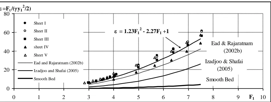
- 0.80 F1 + 1.00 (11) Fig. 8 shows the variation of shear force coefficient with the supercritical Froude number F1 for jumps on corrugated beds for the all shapes of corrugations used in this study along with the mean curve for jumps formed on smooth beds [13]. Also, included in Fig. 8 are the results of [8]. A number of interesting observations could be made from a study of Fig. 8. First, the data for the corrugated beds used in the present study can be represented by one mean curve. This confirms that the bed shear stress on corrugated beds is independent of the shape of corrugations. Second, the trend of the relationship between and F1 is the same for smooth and corrugated beds for the present study and those of [8], [9] and [14]. Third, although the trend of the relation between and F1 is similar, there are considerable differences among the shear stress values for the present study and those of [8], [9] and [14]. For a supercritical Froude number F1 equal to 5, the value of for smooth beds is 1 and the values of for corrugated beds for the present study and those of [8], [9] and [14] are 20, 16, 8, and 22, respectively. It seems that the dynamics of the boundary shear stress on corrugated beds and the factors affecting it are not completely understood and need further investigation so that these discrepancies would be properly explained.
4. CONCLUSION
on sinusoidal, trapezoidal and triangular corrugated beds. It is interesting to know that the normalized jump length for Peterka’s Type II basin is about 6.
The reason for the reduction of the jump -forming tailwater depth appears to be the enhanced bed shear stresses produced by the interaction of the supercritical stream with the bed corrugations. The variation of the integrated bed shear stress on the different shapes of corrugated beds was studied. It was found that all the five corrugated beds used in the present study could be represented by one mean curve confirming that the shear stress on corrugated beds is independent of the shape of corrugations. Also , it was found that the trend of the relationship between and F1 is the same for smooth and corrugated beds for the present study and those of [8], [9] and [14]. Although the trend of the relation between and F1 is similar, there are considerable differences among the values of the shear stress for the present study and those of [8], [9] and [14]. It seems that the dynamics of the boundary shear stress on corrugated beds and the factors affecting it are not completely understood and need further investigation so that these differences would be properly explained.
ACKNOWLEDGM ENT
The author expresses his sincere gratitude to the Research Center of the Faculty of Engineering, King Saud University for supporting this work.
REFERENCES
[1] A. J. Peterka, “ Hydraulic design of stilling basins and energy dissipators” Engineering Monograph No. 25, U.S. Bureau of Reclamation, Denver, 1958.
[2] N. Rajaratnam, “ Hydraulic jumps.” Adv. Hydrosci., 1967, 4, 197–280.
[3] J. A. McCorquodale, “ Chapter 8: Hydraulic jumps and internal flows.” Encyclopedia of fluid m echanics, N. P. Cheremisinoff, ed., Vol. 2, Gulf Publishing, Houston, 1986, 120–173.
[4] W. H. Hager, "Energy dissipators and hydraulic jum p", Kluwer Academic, Dordrecht , 1992.
[5] N. Rajaratnam, “ Hydraulic jumps on rough beds.” Trans. Eng. Inst. Canada, 1968, 11(A-2), 1–8.
[6] W. C., Hughes, J. E. and Flack, “ Hydraulic jump properties over a rough bed.” J. Hydraul. Eng., 1984, 110(12), 1755–1771. [7] S. A., Ead, N., Rajaratnam, C., Katopodis, and F. Ade, “ T urbulent
open-channel flow in circular corrugated culverts.’” J. Hydraul. Eng., 2000, 126(10), 750–757.
[8] S. A., Ead, and N. Rajaratnam, “ Hydraulic jumps on corrugated beds.” Journal of Hydraulic Engineering, ASCE, 2002a, Vol. 128, No. 7, pp. 656-663.
[9] F., Izadjoo, and M. Shafai-Bajestan, “ Effects of T rapezoidal shape corrugated bed on the characteristics of Hydraulic jump.” 17th Canadian Hydrotechnical Conference, Hydrotechnical Engineering: Cornerstone of a Sustainable Environment, Edmonton, Alberta, Canada, 2005, August 17–19.
[10] N. Rajaratnam, "Turbulent jets, Elsevier Science", Amsterdam, T he Netherlands, 1976.
[11] W. H., Hager, and R. Bremen, “ Classical hydraulic jump; sequent depths.” J. Hydraul. Res., 1989, 27(5), 565–585.
[12] S. A., Ead, and N. Rajaratnam, “ Plane turbulent wall jets in shallow tailwater.” J. Eng. Mech., 2002b,128(2), 143–155. [13] N. Rajaratnam, “ T he hydraulic jump as a wall jet.” J. Hydraul.
Div., Am . Soc. Civ. Eng., 1965, 91(5), 107–132.
TABLE I
PRIMARY DETAILS OF EXP ERIMENTS
Expt Sheet F1 R1
U1 (m/s)
y1 (mm)
y2 (m)
y2* (m)
Lj (m) D t/y1 Lj/y2* F 1 2
/2
A1 I 4.1 51047 2.04 25 0.075 0.134 0.220 0.439 0.72 1.644 14.667
A2 I 5.0 61903 2.48 25 0.080 0.165 0.250 0.514 0.72 1.518 25.135
A3 I 5.7 71122 2.84 25 0.095 0.191 0.400 0.503 0.72 2.094 35.192
A4 I 6.4 79275 3.17 25 0.136 0.214 0.500 0.365 0.72 2.334 38.333
A5 I 7.0 86488 3.46 25 0.142 0.235 0.600 0.395 0.72 2.555 49.155
A6 I 7.5 93374 3.73 25 0.145 0.254 0.650 0.430 0.72 2.555 61.506
B1 I 3.0 105054 2.10 50 0.124 0.189 0.220 0.343 0.36 1.166 5.592
B2 I 3.3 116141 2.32 50 0.134 0.211 0.350 0.364 0.36 1.660 7.609
B3 I 3.6 126259 2.53 50 0.146 0.231 0.400 0.368 0.36 1.730 9.569
B4 I 3.9 135624 2.71 50 0.150 0.250 0.430 0.400 0.36 1.720 12.000
B5 I 4.1 142157 2.84 50 0.154 0.263 0.450 0.415 0.36 1.710 13.772
A1 II 4.1 51047 2.04 25 0.060 0.134 0.170 0.552 0.72 1.270 15.073
A2 II 5.0 61903 2.48 25 0.092 0.165 0.230 0.441 0.72 1.396 23.871
A3 II 5.7 71122 2.84 25 0.105 0.191 0.350 0.450 0.72 1.833 33.646
A4 II 6.4 79275 3.17 25 0.121 0.214 0.400 0.435 0.72 1.867 42.632
A5 II 7.0 86488 3.46 25 0.141 0.235 0.430 0.399 0.72 1.831 49.485
A6 II 7.5 93374 3.73 25 0.147 0.254 0.500 0.422 0.72 1.965 60.839
B1 II 3.0 105054 2.10 50 0.110 0.189 0.200 0.417 0.36 1.060 5.978
B2 II 3.3 116141 2.32 50 0.115 0.211 0.300 0.455 0.36 1.423 8.145
B3 II 3.6 126259 2.53 50 0.120 0.231 0.330 0.481 0.36 1.427 10.407
B4 II 3.9 135624 2.71 50 0.133 0.250 0.350 0.468 0.36 1.400 12.646
B5 II 4.1 142157 2.84 50 0.155 0.263 0.400 0.411 0.36 1.520 13.718
A1 III 4.1 51047 2.04 25 0.075 0.134 0.200 0.439 0.72 1.495 14.667
A2 III 5.0 61903 2.48 25 0.100 0.165 0.310 0.393 0.72 1.882 22.500
A3 III 5.7 71122 2.84 25 0.120 0.191 0.470 0.372 0.72 2.461 30.210
A4 III 6.4 79275 3.17 25 0.125 0.214 0.520 0.417 0.72 2.427 41.600
A5 III 7.0 86488 3.46 25 0.150 0.235 0.550 0.361 0.72 2.342 46.333
A6 III 7.5 93374 3.73 25 0.160 0.254 0.650 0.371 0.72 2.555 56.025
B1 III 3.0 105054 2.10 50 0.115 0.189 0.220 0.390 0.36 1.166 5.884
B2 III 3.3 116141 2.32 50 0.130 0.211 0.420 0.383 0.36 1.992 7.778
B3 III 3.6 126259 2.53 50 0.145 0.231 0.530 0.373 0.36 2.293 9.624
B5 III 4.1 142157 2.84 50 0.165 0.263 0.620 0.373 0.36 2.356 13.082
A1 IV 4.1 51047 2.04 25 0.104 0.134 0.515 0.223 0.72 3.849 9.977
A2 IV 5.0 61903 2.48 25 0.123 0.165 0.545 0.253 0.72 3.309 17.621
A3 IV 5.7 71122 2.84 25 0.140 0.191 0.605 0.267 0.72 3.168 24.809
A4 IV 6.4 79275 3.17 25 0.160 0.214 0.870 0.253 0.72 4.061 30.431
A5 IV 7.0 86488 3.46 25 0.170 0.235 1.070 0.276 0.72 4.557 39.788
A6 IV 7.5 93374 3.73 25 0.180 0.254 1.200 0.293 0.72 4.716 48.644
B1 IV 3.0 105054 2.10 50 0.150 0.189 0.550 0.205 0.36 2.916 6.551
B2 IV 3.3 116141 2.32 50 0.160 0.211 0.624 0.241 0.36 2.959 8.047
B3 IV 3.6 126259 2.53 50 0.168 0.231 0.760 0.273 0.36 3.288 9.545
B4 IV 3.9 135624 2.71 50 0.176 0.250 0.900 0.296 0.36 3.600 10.959
B5 IV 4.1 142157 2.84 50 0.180 0.263 1.100 0.316 0.36 4.180 13.525
A1 V 4.1 51047 2.04 25 0.080 0.134 0.355 0.402 0.72 2.653 16.234
A2 V 5.0 61903 2.48 25 0.100 0.165 0.420 0.393 0.72 2.550 25.178
A3 V 5.7 71122 2.84 25 0.120 0.191 0.570 0.372 0.72 2.985 32.889
A4 V 6.4 79275 3.17 25 0.138 0.214 0.780 0.356 0.72 3.641 39.717
A5 V 7.0 86488 3.46 25 0.150 0.235 1.000 0.361 0.72 4.259 49.264
A6 V 7.5 93374 3.73 25 0.163 0.254 1.140 0.359 0.72 4.480 57.411
B1 V 3.0 105054 2.10 50 0.137 0.189 0.584 0.274 0.36 3.096 5.943
B2 V 3.3 116141 2.32 50 0.149 0.211 0.782 0.293 0.36 3.709 8.194
B3 V 3.6 126259 2.53 50 0.157 0.231 0.913 0.321 0.36 3.949 10.116
B4 V 3.9 135624 2.71 50 0.165 0.250 1.070 0.340 0.36 4.280 12.157
B5 V 4.1 142157 2.84 50 0.188 0.263 1.180 0.286 0.36 4.484 12.992
Sheet I : Sinusoidal Corrugated Bed Sheet II : T riangular Corrugated Bed
Sheet III : T rapezoidal (45o side slopes) Corrugated Bed Sheet IV : T rapezoidal (60o side slopes) Corrugated Bed
Sheet V : Rectangular Corrugated Bed
0.00 0.04 0.08 0.12 0.16 0.20
0.0 0.1 0.2 0.3 0.4 0.5 0.6 0.7 0.8
x (m) y (m)
Expt. A1 ( y1=25 mm, F1=4.1) Expt. A2 (y1=25mm, F1=5.0) Expt. A3 (y1=25mm, F1=5.7)
Expt. A4 (y1=25mm, F1=6.4) Expt. A5 (y1=25mm, F1=7.0) Expt. A6 (y1=25mm, F1=7.5) (a)
0.00 0.04 0.08 0.12 0.16 0.20
0.0 0.1 0.2 0.3 0.4 0.5 0.6 0.7x (m) 0.8
y (m)
Legend as in (a)
(b)
0.00 0.04 0.08 0.12 0.16 0.20
0.0 0.1 0.2 0.3 0.4 0.5 0.6 0.7 0.8
x (m)
y (m) (c)
0.000 0.040 0.080 0.120 0.160 0.200
0 0.1 0.2 0.3 0.4 0.5 x(m) 0.6 0.7 0.8
y(m)
0.000 0.040 0.080 0.120 0.160 0.200
0 0.1 0.2 0.3 0.4 0.5 x(m ) 0.6 0.7 0.8
y(m )
Fig. 3. (a-e) Water surface profiles for the (A) series experiments for jumps on (a) Sinusoidal; (b) T rapezoidal (45o side slopes); (c) T riangular; (d) T rapezoidal (60o side slopes); and (e) Rectangular Corrugated beds, respectively
0.0 0.2 0.4 0.6 0.8 1.0 1.2 1.4
0.0 0.4 0.8 1.2 1.6 2.0 2.4 x/Lj 2.8
(y-y1)/(y2-y1)
Expt. A1 (y1=25 mm, F1=4.1) Expt. A2 (y1=25mm, F1=5.0) Expt. A3 (y1=25mm, F1=5.7)
Expt. A4 (y1=25mm, F1=6.4) Expt. A5 (y1=25mm, F1=7.0) Expt. A6 (y1=25mm, F1=7.5) (a)
(d)
(e)
Legend as in (a)
0.0 0.2 0.4 0.6 0.8 1.0 1.2 1.4
0.0 0.4 0.8 1.2 1.6 2.0 2.4 x/Lj 2.8
(y-y1)/(y2-y1)
Legend as in (a)
(b)
0.0 0.2 0.4 0.6 0.8 1.0 1.2 1.4
0.0 0.4 0.8 1.2 1.6 2.0 2.4 x/Lj 2.8
(y-y1)/(y2-y1)
Legend as in (a)
(c)
0.000 0.200 0.400 0.600 0.800 1.000 1.200 1.400
0.000 0.400 0.800 1.200 1.600 2.000 2.400
x/Lj
(y-y1)/(y2-y1)
(d)
0.000 0.200 0.400 0.600 0.800 1.000 1.200 1.400
0.000 0.500 1.000 1.500 2.000 x/Lj 2.500
(y-y1)/(y2-y1)
Fig. 4. (a-e) Normalized Water surface profiles for t he (A) series experiments for jumps on (a) Sinusoidal; (b) T rapezoidal (45o side slopes); (c)
T riangular; (d) T rapezoidal (60o side slopes); and (e) RectangularCorrugated beds, respectively
0 2 4 6 8 10 12
0 2 4 6 8 10 F1 12
y2/y1 Sheet I
Sheet II
Sheet III
sheet -IV
sheet -V
Belanger Equation y2/y1 =0.88 F1
Fig. 5. Variation of the sequent depth ratio (y2/y1) with the Froude number F1
for all Experiments
0 0.2 0.4 0.6 0.8 1
0 2 4 6 8 10 F1 12
D Sheet I
Sheet II
Sheet III
sheet -IV
sheet -V
D =0.37
Fig. 6. Variation of the depth deficit factor (D= (y2*-y2)/y2*) with the Froude number F1
for all Experiments (e)
y2/y1 = 0.88F1 r2 = 0.94
0 2 4 6 8
0 2 4 6 8 10 F1 12
Lj/y2* Sheet I
Sheet II
Sheet III
sheet -IV
sheet -V
Lj/y2*
Fig. 7. Variation of the normalized jump length (Lj/y2 *
) with the Froude number F1
for all Experiments
0 20 40 60 80
0 1 2 3 4 5 6 7 8 9 F1 10
=F/(y1 2
/2)
Sheet I
Sheet II
Sheet III
sheet IV
Sheet V
Ead and Rajaratnam (2002b)
Izadjoo and Shafai (2005)
Smooth Bed
= 1.23F1 2
- 2.27F1 +1
Smooth Bed Izadjoo & Shafai
(2005)
Ead & Rajaratnam (2002b)