Volume 1 Issue 4 JETIR (ISSN-2349-5162)
Review on Application of Worm Pairs in Load
Lifting Devices
1
R. D. Ankush,
2Prof. P. D. Darade
Mechanical Engineering Department 1P.G.M.C.O.E.,Wagholi, Pune,India
2S.I.T.S., Narhe, Pune,India
Abstract - In most of the load lifting devices it is necessary to use a pair of two identical or different parts for the motion
transmission. In most of the devices the pairs used are worm-gear, belt-pulley, rope-pulley, chain-pulley etc. The selection of appropriate pair depends on parameters such as space requirement, type of load to be handled, desired efficiency of the system. In Most of the cases the worm-gear pair is used due to its advantages over other systems such as higher efficiency, compactness and simple construction. It also exhibits the self-locking ability which allows the input member (gear) to rotate the output member (worm) in either directions but it does not allow the output member to rotate the input member when the driving force on input member is suddenly reduced. This self-locking ability is also useful for the safety of operators working in the vicinity of this system. It prevents the probable accidents due to falling of lifted load when the driving force on the input member is removed or suddenly released. This paper is focused on the study of probable alternative methods for the conventional worm and gear system to achieve better efficiency and simplicity. The self-locking ability can also be obtained with help of worm pair system. So our paper comprises of the various uses of self-locking ability of mating worm pair system. In our paper various systems are studied in which the self-locking ability of worm pair system is used.
Keywords -Mating worm, self-locking, load lifting devices
I. INTRODUCTION
Load lifting devices are mostly used for lifting, moving and store the goods within a company or at site. In most of the applications worm gear drive is used to lift and carry the loads. This drive is mostly used due to its simplicity and ability of providing desirable torque with the help of different gear ratios. This drive mostly contains of a worm and gear pair. The worm acts as an input whereas gear acts as output. The motor is used to provide required input rotary motion to the worm which in turn transfers this rotary motion to the gear. The load drum is provided to the gear shaft which rotates due to rotary motion of gear and in turn the load gets lifted. The higher speed reduction ration can be obtained with the help of this worm gear system. There are some losses in this system due to the friction between the worm and gear. This worm gear system have an ability of self-locking due to which the input member can rotate the output member in either directions but when the driving force on input member is suddenly removed or it is reduced then it doesn’t allow the output member to rotate the input member. This ability of self-locking ensures the safe operation of any material carrying system. It also acts as safety feature for the motor in order not to get damaged due to its opposite rotation. This worm gear system has some important advantages like self-locking ability and simplicity in construction but it also has some disadvantages like poor efficiency. It hardly provides the efficiency around 40 %. This is due to its friction between worm and gear. So our main aim behind this review is that to find out the alternate pair of objects which also has the self-locking ability, higher efficiency as compared to worm gear system and simple in construction. In this paper we have summarized the use of worm pair in various engineering applications. This worm pair also has the ability of self-locking as that of worm and gear pair. This ability plays a vital role in reliability and safety for the people working around this system.
II. LITERATURESURVEY
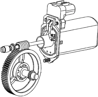
Fig. 1. Arrangement of a worm and worm wheel
Jakhin popper and Kiryat Motzkin [2] have done a research on cooperating wedges and including a pair of mating worms. The invention in one property includes self-locking or one way gears in which the function of driving or driven gears is not interchangeable. The purpose of the invention is to provide self-locking gears which have higher efficiency. A further purpose is to obtain self-locking gears in which a wide variety of selected transmission ratios are possible, even 1:1. A further purpose is to produce a locking gear combination in which equal power is required to raise and to lower the load. A further purpose is to provide self-locking gears in which the axes are disposed at a smaller angle than 90° to one another and almost parallel. A further purpose is to provide self-locking gears such that the driving gear can drive the driven gear in either direction, but as soon as the driven gear exhibits a tendency to over travel it will bind the combination and prevent all motion. A further purpose is to impart partial or complete response of a driven gear to the driving action. A further purpose is to produce a combination of self-locking gears, both of which are worms, which can be cut on a standard thread cutting lathe or automatic screw machine.
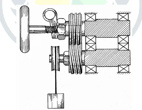
Fig. 2. General Arrangement of worm pair Fig. 3.
Wiktor Panjuchin and Vladimir [3] have done the work related to self-locking worm pair with parallel axes with two worm having involutes herring bone teeth and linear contact of both worms as well as the tools to produce these gears they design to provide self-locking simple tool with reproducible method with quasi involutes profiles for its teeth.
Volume 1 Issue 4 JETIR (ISSN-2349-5162)
Alfonso Hilado, Paranaque, Rizal [4] of Republic of the Philippines invented the combination of worm pair in differential gear assembly usually employed in the power transmission systems of automobile between the prime mover and two oppositely disposed vehicle-driving traction wheels allows for differential movement of the driving traction wheels on opposite sides of the vehicle, particularly when the vehicle is moving in a circular path Since the advent of automotive land vehicles, generally known as “automobiles,” a planetary spur or bevel gear differential mechanism has been employed which has well known drawbacks, such as when one of the traction driving wheels of the vehicle is on or encounters a slippery portion of the ground or supporting surface, it loses its traction with the said surface and spins freely ‘while the opposite traction wheel loses its power to drive the ‘vehicle forward. While attempts have been made previously to overcome the above-mentioned shortcomings, such proposals have had little or no public acceptance, which is believed to be due to the fact that, in attempting to overcome said inherent defect, the structures that have been proposed for this purpose are not only more complicated and expensive in construction but also compromise between applying power efficiently to both driving traction wheels and obtaining good differential of said traction wheels or else, are of a type of gearing and organization. as is impractical or noisy and costly or not otherwise durable in long continued use to which automobiles are usually subjected.
Fig. 4. Self-locking differential mechanism
David Pessen [5] of Israel has developed the quick release mechanism for self-locking system the occasion can arise where it becomes desirable to quickly release the load. This could be accomplished by introducing a clutch between the pulley and worm but such clutches are generally expensive and space consuming. This invention comprises of a modification of a self-locking mating worm drive such as it consist of a nut mounted on one of the worm shaft with a very large pitch angle, such as it is not self-locking . This nut keeps the two warm in mesh and axial motion of the nut is prevented by a tapered key is removed, the axial press of the worm pushes the nut sideways until the two worms disengage. Thus the self-locking property can thus be removed at will.
Fig. 5. Quick release mechanism for worm pair system
Fig. 6. Automatic dual ratio motion convertor
Adam Macheta and Sebastian Kania[7] of (EC Engineering) have worked on the power losses in worm gears transmissions. The efficiency of the worm gear depends on the coefficient of friction and the lead angle. In order to obtain a worm gear with high efficiency it is recommended to use the lead angle in the range between 150 and 300.
Fig. 7. Variation of efficiency according to change in lead angle
William J. Roantree and Port Washington [8] of New York generate a gear mechanism for converting the rotary to linear motion. The mechanism includes a lead screw having a thread of contact pitch the thread being I driving the relationship with one or more differential having a thread same pitch the roller being mounted upon the carriage mounted for linear travel along teeth of rotary motion to linear motion has been secured by lead screw. It has slow speed conversion of rotary motion to linear motion has been
Volume 1 Issue 4 JETIR (ISSN-2349-5162)
III.IMPLICATIONS OF THIS SURVEY
This survey contributes to the design and development of mating worm pair for their use in load lifting devices. The main property which is a worm gear system exhibit is its self-locking ability. We have also considered the system of worm pair due to its property of self-locking as that of worm and gear system. Due to this property worm pair can be used in various applications such as differential gear mechanism used in vehicles, self-locking system for load lifting, automatic dual ratio motion convertor, etc. Out of all these applications I have selected to work on worm pair system.
IV.CONCLUSION
We have proposed the system for lifting the load which uses the pair of worms instead of conventional worm and gear system. The main intension behind development of this system is to improve the efficiency of the conventional system and also to improve the reliability and safety of conventional system, also the cost of manufacturing and space requirement is also important for the development of this system.
REFERENCES
[1] Fenge Li Shenzhen & Jing Ning Ta of Hongkong “Worm Gear Drive.” United States Patent Office No.8, 051,737 B2 dated on 8 Nov 2011
[2] Jakhin Boaspopper & Kiryat Motzkin of Israel “Cooperating Wedges including Mating Worm.” United States Patent Office No.2, 973,660 dated on 07 Mar 1961
[3] Winker W. Panjuchin & Vladimir of Russia “Self-locking Dual Worm Gear & The Tools Needed to Produce it.” United States Patent Office No.5, 522,278
[4] Alfonso Hilado, Paranaque, Rizal of Republic of the Philippines “Self-locking Differential Mechanism.” United States Patent Office No.3,095,761 dated on 2 July 1963
[5] David W. Pessen of Israel “Quick Release Mechanism for Self-Locking Mating Worms.” United States Patent Office No.3, 776,060 dated on 04 Dec 1973
[6] Robert W.Jenny & Believue Wash from the Boeing Company of Washington “Automatic Anti Friction Dual ratio Motion Convertor.” United States Patent Office No.3, 295,385 dated on 3 Jan 1967
[7] Adam Macheta and Sebastian Kania of (EC Engineering) “Literature Survey : Worm Gear Losses .”
[8] William J. Roantree of Port Washington, N.Y.”Gearing Mechanism” United States Patent Office No.3,508,452 dated on 28 April 1970
![Fig. 7. Variation of efficiency according to change in lead angle William J. Roantree and Port Washington [8] of New York generate a gear mechanism for converting the rotary to linear](https://thumb-us.123doks.com/thumbv2/123dok_us/1385038.1649314/4.595.167.430.321.527/variation-efficiency-according-william-roantree-washington-mechanism-converting.webp)
