JETIR1511017 Journal of Emerging Technologies and Innovative Research (JETIR) www.jetir.org 95
A NEW ADAPTIVE BEAMFORMING ALGORITHM
FOR SMART ANTENNA
AVANISH YADAV1 DIVYANSHU RAO2, RAVI MOHAN3
1- Dept of ECE, ME student, SRIT, JABALPUR, M.P., INDIA
2-Dept of ECE, Prof., SRIT, JABALPUR, M.P., INDIA
3- Dept of ECE, H.O.D., SRIT, JABALPUR, M.P., INDIA
ABSTRACT: Beam forming in smart antenna is recognized as a promising technology for higher user capacity in 3G
wireless networks by effectively reducing multipath and co-channel interference. Smart Antennas, also known as multiple antennas or adaptive array antennas, are used to increase the efficiency of the wireless communication systems. Beam forming is a powerful means of increasing capacity, data rates and coverage of the cellular system. The beam forming were used to generate pencil beams pattern in desired direction, so as to receive signals from a specific direction and attenuate signals incoming from any other directions. This paper introduces a New Modified-Normalized least mean square (NM-NLMS) algorithm to improve interference suppression in adaptive beam forming smart antenna system. The new proposed algorithms provides fast convergence rate, higher interference suppression capability and low level of minimum Mean Square Error (MSE) at the steady state compared other conventional (i.e. LMS, NLMS, LLMS, VSSNLMS& MIR-LMS) algorithms.
KEYWORDS: Smart Antenna, LMS, NLMS, LLMS, MI-NLMS, VSSNLMS, Beam forming, MIR-LMS, convergence speed.
I.INTRODUCTION
A smart antenna consists of number of elements (referred to as antenna array), whose signals are processed adaptively in order to exploit the spatial dimension of the mobile radio channel. All elements of the adaptive antenna array have to be combined (weighted) in order to adapt to the current channel and user characteristics. This weight adaptation is the “smart” part of the smart antenna, which should hence be called “adaptive antenna” [1].
To achieve high data rates and high capacity in communication it is needed to reducing the interferences and noise which greatly affects the performance of cellular system, while have to increase the desired signal power. With limited spectrum availability, achieving this goal is difficult due to co channel and adjacent channel interferences. So more advanced technologies are needed to fulfill the need of next generation wireless mobile communication. In recent decades, beamforming antennas for mobile wireless communications have received enormous interest. Beamforming is a promising technology which reduces interferences and noise[2].
The adaptive beamforming algorithm improves the output of the array beam pattern in a way which it maximizes the radiated power where it will be produced in the directions of the desired mobile users. Moreover, deep nulls are produced in the directions of undesired signals which symbolize co-channel interference from mobile users in the adjacent cells. Before adaptive beamforming, direction of arrival estimation is used to specify the main directions of users and interferers[ 4]. The complex weights (w) for the antenna elements are carefully chosen to give the desired peaks and nulls in the radiation pattern of the antenna array. In a simple case, the weights may be chosen to give one central beam in some direction, as in a direction-finding application [6]. The adaptive system takes advantage of its ability to effectively locate and track various types of signals to dynamically minimize interference and maximize intended signal reception [12].
II. LITERATURE REVIEW
A new adaptive algorithm, called least mean square least mean square (LLMS) algorithm, which employs an array image factor, , sandwiched in between two least mean square (LMS) algorithm sections, is proposed for different applications of array beamforming. Simulation results show that LLMS algorithm is superior in convergence performance over earlier LMS based algorithms [3]. Author introduces the Robust Interference Suppression Using a New LMS Based Adaptive Beamforming Algorithm in this algorithm variable step size NLMS algorithm is used to improve interference suppression in smart antenna system [4]. Matrix Inverse Robust Least Mean Square (MIR-LMS) algorithm is propose where author’s uses the sample Matrix Inversion (SMI) algorithm and ratio parameters to control the contribution of normalized product vectors in the weight upgradation process the MIR-LMS algorithm author’s find that the signal response is improved, the convergence rate is faster [9]. LMS algorithm has good performance except that it has a very slow rate of convergence. SMI improves the convergence speed at the cost of more computational complexity and singularity problem of correlation matrix. It is shown that RLS algorithm overcomes the problems of SMI and improves the rate of convergence of LMS at the cost of higher SLL and lower null depths. It is observed that the CGM algorithm has the fastest convergence and greatest null depths ensuring good performance [7].
III. BEAMFORMING ALGORITHM
JETIR1511017 Journal of Emerging Technologies and Innovative Research (JETIR) www.jetir.org 96
In the non-blind algorithms, the adaptive weights of the array beamformer are usually adapted according to a specified criterion, such as minimization of mean square error (MMSE), or maximization of the signal to interference plus noise signal (MSINR). An error signal, produced by comparing the output signal with a reference signal, is used to iteratively adjust the weights of the beamformer to their optimal values, Wopt , so as to obtain the minimum MSE. The trained algorithms could be
classified according to their adaptive criterion: least-mean squares method (LMS), sample matrix inversion (SMI) or least-squares method (LS), and recursive least-squares method (RLS) [11].
Basic idea behind LMS filter is to approach the optimum filter weights by updating filter weights in manner to converge optimum filter weight. Algorithm starts by assuming small weights (zero in most cases) and at each step by gradient of mean square error weights are updated [5]. The performance of the algorithm depends on the step size parameter, which controls the convergence speed and the variation of the learning curve. LMS algorithm uses the Method of Steepest-Descent to update the weight vector [8].
The normalized least mean square (NLMS) algorithm has superior convergence properties than the least mean square (LMS) algorithm. However, weight noise effect of the NLMS algorithm is large so that the steady state residue power is larger than that for the LMS algorithm [7].
In MI-NLMS algorithm, the SMI algorithm is utilized to determine the optimum weight vectors assigned to each of the antenna elements of the array instead of arbitrary value before calculating the final weight vector. The weight is calculated only for the first few samples or for a small block of incoming data. The weight coefficients derived by SMI algorithm are set as initial coefficients and are updated by introducing NLMS algorithm [10].
IV. PROPOSED METHOD
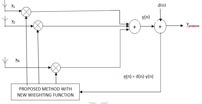
The input signals picked up by the antenna elements with initializing the weighting function are first processed by a proposed algorithm (New Modified Normalized-LMS algorithm). To enhance the convergence rate overall algorithm, the previous error sample, eM-NLMS, from the M-NLMS algorithm stage is fed back to combine with the current error sample, eNM-NLMS, of the NM-NLMS algorithm stage to form the overall error signal, eNM-NLMS, for updating the tap weights of the proposed algorithm stage. This may improve the stability of the proposed algorithm against sudden changes in the input signals. As shown in Figure 1, a common external reference signal is used for proposed (NM-NLMS) algorithm stages. This mode of operation will from now on be referred to as the external referencing mode.
Figure 1: Adaptive Beamforming Algorithm using Proposed Method
4.1 FLOWCHART OF PROPOSED ALGORITHM
Let y(n) be the beamformer output, the output at time n, y(n) is given
yj(n) = Wj-1H xj(n)………(1)
Where x(n) is the input signal and the H denotes Hermitian (complex conjugate) transpose. The weight vector w is a complex vectors. The process of weighting these complex weights w1 … … …wk adjusted their amplitudes and phases such that when added together forms the desired beam & j= 1……..N-1.
if j=1 then output y1(n) = WHx1(n)……….(2) if j=2 then output y2(n) = W1H x2(n)………...(3) if j=3 then output y3(n) = W2H x3(n)………...………(4)
where w are the adaptive weighting with initializing the weighting function by zero Calculation of w,w1,w2 as:
The overall error rate:
e j2NMNLMS = ‖ej – ej+1‖ 2
JETIR1511017 Journal of Emerging Technologies and Innovative Research (JETIR) www.jetir.org 97
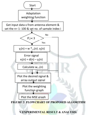
With help of my proposed algorithm flowchart of algorithm as shown in figure 2 overall convergence rate is improved as
compared to other conventional algorithm.
FIGURE 2: FLOWCHART OF PROPOSED ALGORITHM
V.EXPERIMENTAL RESULT & ANALYSIS:
Computer simulations based on the MATLAB [7.8.0.347(R2009a)] have been carried out to evaluate the performances of the Proposed algorithm with the other 4 algorithm i.e. NLMS, LLMS, VSSNLMS, MIR-LMS schemes have been evaluated in the presence of an external reference signal. The convergence performances of these schemes are compared based on the ensemble average squared error (e2) obtained from 100 individual simulation runs. These results have been obtained for different values of input SNR.
5.1 SIMULATION RESULTS AND ANALYSIS
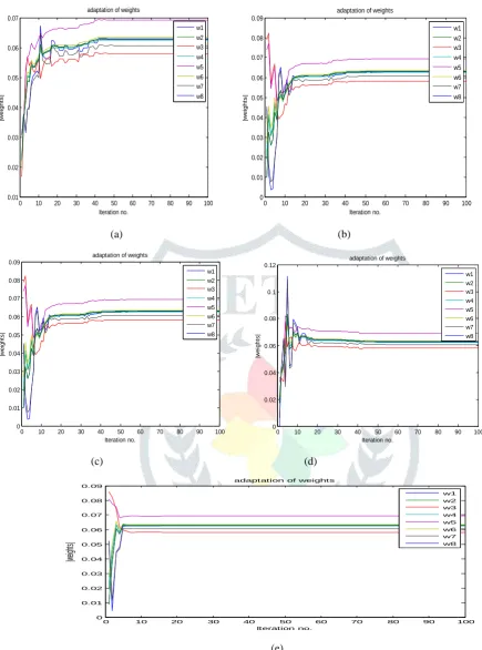
The desired signal is taken as a cosine signal at an angle of 0°. Two interfering signals are considered at angles of 20° and -40°. For this analysis, N=16 and d=0.5λ are chosen. Figure 3 shows that the adaptations of weights of the proposed algorithm with other conventional algorithm. The proposed algorithm converges to their optimum values in just 5 iterations. This convergence is much faster than NLMS (50 iterations), LLMS (40 iteration), VSSNLMS (30 iteration) & MIR-LMS (25 iteration).
TABLE 6.1: Rate of convergence for each algorithm with Different SNR
S.No. Algorithm Rate of convergence
SNR=5 dB
SNR =10 dB
SNR=15 dB
SNR= 20 dB
SNR = 25 dB
SNR =30 dB
1. NLMS 42 44 43 45 44 45
2. LLMS 40 44 43 41 40 40
3. VSSLMS 25 27 29 30 30 30
4. MIR-LMS 20 23 25 25 25 25
5. PROPOSED 4 5 5 5 6 6
Start
Adaptation
weighting function
Get input data x from antenna element &
set the n= 1: 100 & set no. of sample index j
y
j(n) = w *
j-1(n) .x
j(n)
Error signal
e
j(n) = d(n) – y
j(n)
Plot the desired signal &
array output signal
Plot the weighting
function graph
Plot the MSE graph
If j < 3
Calculate w
j-1(n)
JETIR1511017 Journal of Emerging Technologies and Innovative Research (JETIR) www.jetir.org 98
(a) (b)
(c) (d)
(e)
Figure 3: Convergence Rate of the weight vectors for: a) NLMS algorithm, b) LLMS Algorithm, c) VSSNLMS Algorithm, d)
MIR-LMS Algorithm & e) Proposed Algorithm.
CONVERGENCE RESULT OF PROPOSED ALGORITHM
Figures 4 show the convergence behaviors of conventional method (i.e. NLMS, LLMS, VSSNLMS, and MIR-LMS) & proposed schemes.
From figure 4 (a) desired signal is shown by green cross sign, output of NLMS algorithm is shown by black line, output of LLMS algorithm is shown by green line, output of VSSNLMS is shown by blue line, output of MIR-LMS is shown by red line & output of proposed algorithm is shown by blue circle sign from the comparison it is easy to conclude that antenna output is more accurate in proposed Algorithm as compared to the other conventional algorithm.
In figure 4 (c) shows the ensemble average of the mean square error (e2) in which black line shows the error plot for NLMS algorithm, green line shows the error plot for NLMS algorithm, blue line shows the error plot for VSSNLMS algorithm,
0 10 20 30 40 50 60 70 80 90 100
0.01 0.02 0.03 0.04 0.05 0.06 0.07 Iteration no. |w e ig h ts |
adaptation of weights
w1 w2 w3 w4 w5 w6 w7 w8
0 10 20 30 40 50 60 70 80 90 100
0 0.01 0.02 0.03 0.04 0.05 0.06 0.07 0.08 0.09 Iteration no. |w e ig h ts |
adaptation of weights
w1 w2 w3 w4 w5 w6 w7 w8
0 10 20 30 40 50 60 70 80 90 100
0 0.01 0.02 0.03 0.04 0.05 0.06 0.07 0.08 0.09 Iteration no. |w e ig h ts |
adaptation of weights
w1 w2 w3 w4 w5 w6 w7 w8
0 10 20 30 40 50 60 70 80 90 100
0 0.02 0.04 0.06 0.08 0.1 0.12 Iteration no. |w e ig h ts |
adaptation of weights
w1 w2 w3 w4 w5 w6 w7 w8
0 10 20 30 40 50 60 70 80 90 100
0 0.01 0.02 0.03 0.04 0.05 0.06 0.07 0.08 0.09 Iteration no. |we igh ts|
adaptation of weights
JETIR1511017 Journal of Emerging Technologies and Innovative Research (JETIR) www.jetir.org 99
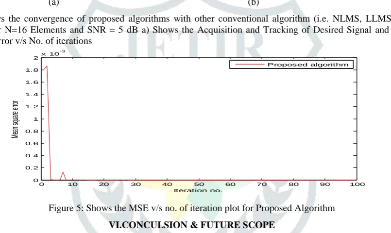
red line shows the error plot for VSS-LMS algorithm & blue cross sign shows the proposed algorithm. The proposed algorithm schemes are able to converge within a few iterations to a low error floor.
(a) (b)
Figure 4: Shows the convergence of proposed algorithms with other conventional algorithm (i.e. NLMS, LLMS, VSSNLMS, MIR-LMS) for N=16 Elements and SNR = 5 dB a) Shows the Acquisition and Tracking of Desired Signal and b) Shows the Mean Square Error v/s No. of iterations
Figure 5: Shows the MSE v/s no. of iteration plot for Proposed Algorithm
VI.CONCULSION & FUTURE SCOPE
A novel method for improving the convergence rate, as well as reducing the steady state error of a conventional NLMS algorithm, is proposed in this paper. The convergence speed of the proposed algorithm is faster than that of the other conventional NLMS algorithm. Algorithms are shown to have rapid convergence, typically within a few iterations, as well as minimum error. In future the proposed algorithm used with higher order modulation schemes, such as OFDM and 64 QAM are used in modern cellular communications systems, so that they can lead to an increase in the detection range of radar and sonar systems, and the also increasing the capacity of mobile radio communication systems.
REFERENCE
1. Balasem. S.S et.al : “Beamforming Algorithms Technique by Using MVDR and LCMV” World Applied Programming, Vol (2), Issue (5), May 2012. 315-324 Special section for proceeding of International E-Conference on Information Technology and Applications (IECITA) 2012
2. Nu Nu Yi et.al : “Modeling and Simulation of Adaptive Beamforming for Mobile Communication” International Journal of Engineering Trends and Technology (IJETT) – Volume 9 Number 15 - Mar 2014 page no. 753-758.
3. Jalal Abdulsayed Srar et.al: “Adaptive Array Beamforming Using a Combined LMS-LMS Algorithm” IEEE Transactions on Antennas and Propagation, VOL. 58, NO. 11, NOVEMBER 2010, page no. 3545-3557.
4. Ali Hakam et.all : “Robust Interference Suppression Using a New LMS Based Adaptive Beamforming Algorithm” 17th IEEE Mediterranean Electrotechnical Conference, Beirut, Lebanon, 13-16 April 2014.
5. Arun Kumar Singh et.al: “ Beamforming Showing Effect on BER with Change in Antenna Configuration” International Journal of Computer Applications Volume 112 – No. 6, February 2015 page no. 20-23.
6. Praveen P Likhitkar and Chandrasekhar N Deshmukh : “Beamforming for MIMO-OFDM Wireless Systems” European Journal of Advances in Engineering and Technology, 2015, 2(6): page no. 14-19.
0 10 20 30 40 50 60 70 80 90 100
-1.5 -1 -0.5 0 0.5 1 1.5
No. of Iterations
S
ig
n
a
ls
Desired signal Array output of NLMS Array output of LLMS Array output of VSSNLMS Array output of MIR-LMS Array output of Proposed method
0 10 20 30 40 50 60 70 80 90 100
0 0.1 0.2 0.3 0.4 0.5 0.6 0.7 0.8 0.9 1
Iteration no.
M
e
a
n
s
q
u
a
re
e
rr
o
r
NLMS LLMS VSSNLMS MIR-LMS Proposed algorithm
0 10 20 30 40 50 60 70 80 90 100
0 0.2 0.4 0.6 0.8 1 1.2 1.4 1.6 1.8
2x 10
-3
Iteration no.
Me
an
sq
ua
re
err
or
JETIR1511017 Journal of Emerging Technologies and Innovative Research (JETIR) www.jetir.org 100
7. Prerna Saxena, A.G. Kothari: “Performance Analysis of Adaptive Beamforming Algorithms for Smart Antennas” 2014 International Conference on Future Information Engineering science direct, IERI Procedia 10 ( 2014 ) 131 – 137. 8. Minal. A. Nemade et.al : “Analysis of LMS and NLMS Adaptive Beamforming Algorithms” International Journal of
Engineering Research & Technology (IJERT) Vol. 3 Issue 7, July – 2014.
9. Kapil Dungriyal et.al : “ Performance of MIR-LMS algorithm for adaptive beam forming in Smart Antenna” IJISET - International Journal of Innovative Science, Engineering & Technology, Vol. 1 Issue 5, July 2014 .
10. MOHAMMAD Tariqul Islam et.al : “MI-NLMS adaptive beamforming algorithm for smart antenna system applications” Journal of Zhejiang University SCIENCE A, 2006 7(10) page no.1709-1716.
11. Jalal Abdulsayed Srar : “Adaptive Antenna Array Beamforming Using A Concatenation of Recursive Least Square and Least Mean Square Algorithms” Curtin University June 2011.
12. RK Jain et.al: “Smart Antenna for Cellular Mobile Communication” VSRD-IJEECE, Vol. 1 issue 9, 2011, page no. 530-541.
13. Omar Mehanna, Student Member, IEEE et.al: “Joint Multicast Beamforming and Antenna Selection” IEEE Transactions on Signal Processing, VOL. 61, NO. 10, MAY 15, 2013.
14. D. B. Salunke et.al : “ Analysis of LMS, NLMS and MUSIC Algorithms for Adaptive Array Antenna System” International Journal of Engineering and Advanced Technology (IJEAT), Volume-2, Issue-3 February 2013 page no.130-133.