Rajampet, Andhra Pradesh, India.
2
Assistant Professor, Dept of EEE, Annamacharya Institute of Technology & Sciences, Rajampet, Andhra Pradesh, India
3PG Student, Dept of EEE, Annamacharya Institute of Technology & Sciences,
Rajampet, Andhra Pradesh, India
Abstract:-
This paper presents a method of maximum power point tracking, MPPT using adaptive fuzzy logic control for grid connected photovoltaic system. The system composed of photovoltaic module, boost converter and the fuzzy logic controller. The maximum power point tracking control is based on adaptive fuzzy logic to control ON/OFF time of MOSFET switch of boost converter. The complete simulation results using Simulink software for the whole system containing the PV array, boost converter, and fuzzy controller were presented. The control strategy for the boost converter and the whole system is carried out by using field programmable gate array (FPGA). The FPGA used is a Spartan 3E from Xilinx. The code of the control system is shown in VHDL language.Index Terms-
Maximium power point tracking, fuzzy logic controller ,photovoltaicarray,Pemfc(proton exchangemembrane fuel cell ) modelI.
INTRODUCTION
Renewable energy is currently widely used. One of these resources is solar energy. The photovoltaic (PV)array normallyuses a maximum power point tracking (MPPT) technique to continuously deliver the highest power to the load when thereare variations in irradiation and temperature. The disadvantage of PV energy is that the PV output power depends on weather conditions and cell temperature, making it an uncontrollable source. Furthermore, it is not available during the night. In order to overcome these inherent drawbacks, alternative sources, such as PEMFC, should be installed in the hybrid system. By changing the FC output power, the hybrid source output becomes controllable. However, PEMFC, in its turn, works only at a high efficiency within a specific power range [1], [2]. The hybrid system can either be connected to the main grid or work autonomously with respect to the grid-connected mode or islanded mode, respectively. In the grid-connected mode, the hybrid source is connected to the main grid at the point of common coupling (PCC) to deliver power to the load. When load demand changes, the power supplied by the main grid and hybrid system must be properly changed. The power delivered from the main grid and PV array as well as PEMFC must be coordinated to meet load demand. Generally the hybrid source has two control modes: 1) unit-power control (UPC) mode and feeder-flow control (FFC) mode. In the UPC mode, variations of load demand are compensated by the main grid because the hybrid source output is regulated to reference power. Therefore, the reference value of the hybrid source output must be determined. In the FFC mode, the feeder flow is regulated to a constant, the extra load demand is picked up by the hybrid source, and hence, the feeder reference power must be known. Here Fuzzy logic or fuzzy set theory is a new method of controlling the MPPT is implemented in obtaining the peak power point. It has the advantage of being robust, fast in response. Fuzzy controller operates in two basic modes coarse and fine modes. The proposed fuzzy operating strategy is to coordinate the two control modes and determine the reference values of the fuzzy control so that all constraints are satisfied. This operating strategy will minimize the number of operating mode changes, improve performance of the system operation, and enhance system stability.
II. SYSTEM DESCRIPTION
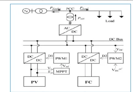
A. Structure of Grid-Connected Hybrid Power System: The system consists of a PV-FC hybrid source with the main gridconnecting to loads at the PCC as shown in Fig. 1.
Figure 1.Grid connected PV-FC hybrid system
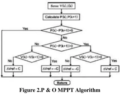
The dc/dc connected to the PV array works as an MPPT controller. Many MPPT algorithms have been proposed in the literature, such as incremental conductance (INC), constant voltage (CV), and perturbation and observation (P&O). The P&O method has been widely used because of its simple feedback structure and fewer measured parameters [7]. The P&O algorithm with power feedback control [8]–[10] is shown in Fig. 2.As PV voltage and current are determined, the power is calculated. At the maximum power point, the derivative dp/dv is equal to zero. The maximum power point can be achieved
by changing the reference voltage by the amount of
vref
.
B. PV Array Model
The mathematical model [3], [4] can be expressed as
I
I
ph
I
sat{exp[
q
/
AKT
(
V
I
RS)]
1}
…. ……….(1)Equation (1) shows that the output characteristic of a solar cell is nonlinear and vitally affected by solar radiation, temperature, and load condition. Photocurrent
I
ph is directly proportional to solar radiationG
aI
ph(G
a)=I
scG
a/
G
as……….(2)The short-circuit current of solar cell
I
sc depends linearly on cell temperatureI
sc(
T
)
I
scs[1
I
sc(
T
T
s)]
... (3)
Thus, Iph depends on solar irradiance and cell temperature
I
ph(
Ga
,
T
)
I
scsG
a/G
asI
scs[1
I
sc(
T
T
s)]
(4) ...
I
satdepends on solar irradiation and cell temperature and can be mathematically expressed as followsI
sat(
G
a,T
)
I
ph(
G
a,T
) /
e
(
V
oc(
T
) /
Vt
(
T
))
1
……….(5)Figure 2.P & O MPPT Algorithm
C. PEMFC Model
The PEMFC steady-state feature of a PEMFC source is assessed by means of a polarization curve, which shows the nonlinear relationship between the voltage and current density. ThePEMFC output voltage is as follows [5]:
V
out
E
Nerst
V
act
V
ohm
V
conc……… ………. (6)Where is the “thermodynamic potential” of Nerst, which represents the reversible (or open-circuit) voltage of the fuel
cell. Activation voltage drop
V
act is given tafel equation asV
act
T
[
a
b
ln(
I
)]
where are the constant terms in expressed as
V
ohm
IR
ohm (7)theTafel equation (in volts per Kelvin). The overall ohmic voltage drop
V
ohm can be (8)The ohmic resistance
R
ohmof PEMFC consists of the resistance of the polymer membrane and electrodes, and the resistances of theelectrodes
.The concentration voltage drop
V
conc can be expressed asV
conc
(
RT
/
ZF
)ln(1
I
/
I
limit)
. (9)III. FUZZY CONTROLLER
A. Fuzzy ControllerThis is the table of prefixed scales, which indicates the “location” of the peak power point A perturb and observe method is employed in the project due to the easy manipulation of the module and more importantly, low power loss through the process.
The IncCond method only offers little improvement over the P&O method underslowly changing atmospheric conditions. Different modules and schemes have been usedto implement peak power point tracking using a microcontroller. One of those techniques which are often used is one that based on the dP/dVmethod . Other methods include heavy mathematical calculation and modeling . Due to the lack of resource on the PIC microcontroller and the complexity in programming, mathematical modeling method is not recommended. On the other hand, dP/dV method offers simpler design and quickerresponse as well as a stable solution. Therefore it is used in this work. It also offers several other useful features such as good steady state and transient response, flexibility in the control algorithm.
B. Logic Controller
Figure 4.Fuzzy logic controllerI (basic model)
C. Fuzzy Knowledge Base Controller
The fuzzy knowledge base controller is basic part of fuzzy logic control which is composed of 3 parts: Fuzzifications inference engine and defuzzification as we shown in the fig.4 and we will describe as below.
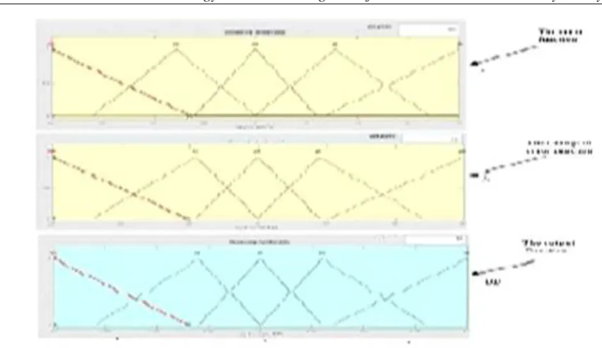
1) Fuzzifications
Figure 5. Fuzzu logic membership after tuning
2) Inference Method
The composition operation by which a control output can be generated. Several composition methods such as MIN and DOT heve been proposed in the literature. The commonly used method is MAX-MIN (AND connection) as we used in our search . The output membership function of each rule is given by the MIN (minimum operator, MAX (maximum) operator. Table 2 shows the rule table for fuzzy logic controller.
(3) Defuzzification
As the plant usually required a nonfuzzy value of control, a defuzzification stage is needed. Defuzzificaion for this system is the height method. The height method is both very simple and very fast method.
Matlab based simulink model
b. Operation Strategy of the Whole System
Simulation Results without hysteresis
2. a. Operation Strategy of the Hybrid System
[1].
T. Bocklisch, W. Schufft, and S.Bocklisch, “Predictive and optimizing energymanagement of photovoltaicfuel cell hybrid systems with shorttimeenergy storage,” in Proc. 4th Eur. Conf. PV-Hybrid and Mini-grid 2008,pp.8-15.[2]. J. Larmine and A. Dicks, Fuel Cell Systems Explained. New York: Wiley, 2003.
[3]. W. Xiao, W. Dunford, and A. Capel, “A novel modeling method for cells,” in Proc. IEEE 35th Annu. [4]. Power Electronics Specialists Conf.,
[5].
D. Sera, R.Teodorescu and P. Rodriguez, “PV panel model based on datasheet values,” in Proc. IEEE IntSymp Industrial Electronics, Jun. 4–7, 2007, pp. 2392–2396.[6]. C. Wang, M. H. Nehrir, and S. R. Shaw, “Dynamic models and model validation for PEM fuel cells using electrical circuits,” IEEE Trans. Energy Convers, vol. 20, no. 2, pp. 442–451, Jun. 2005.
[7]. C. Hua and C. Shen, “Comparative study of peak power tracking techniques for solar storage system,” in Proc. 13th Annu. Applied Power Electronics Conf. Expo., Feb. 1998, vol. 2, pp. 679–685.
[8]. A. Hajizadeh and M. A. Golkar, “Power flow control of grid-connected fuel cell distributed generation systems,” J. Elect. Eng. Technol., vol. 3, no. 2, pp. 143–151, 2008.
[9]. C. Hua and J. R. Lin, “DSP-based controller application in battery validation for PEM fuel cells using electrical circuits,” IEEE Trans.
[10]. Energy Convers., vol. 20, no. 2, pp. 442–451, Jun. 2005.
[11]. C. Hua and C. Shen, “Comparative study of peak power tracking techniques for solar storage system,” in Proc. 13th Annu. Applied Power Electronics Conf. Expo., Feb. 1998, vol. 2, pp. 679–685.
[12]. A. Hajizadeh and M. A. Golkar, “Power flow control of grid-connected fuel cell distributed generation systems,” J. Elect. Eng. Technol., vol. 3, no. 2, pp. 143–151, 2008.
[13]. C. Hua and J. R. Lin, “DSP-based controller application in battery storage of photovoltaic system,” in Proc.22nd IEEE Int. Conf. Industrial Electronics,Control, and Instrumentation, Aug. 5–10, 1996, vol.3, pp. 1750–1810.
[14]. C. Hua, J. Lin, and C. Shen, “Implementation of a DSP-controlled photovoltaic system with peak power tracking,” IEEE Trans. Ind. Electron,vol. 45, no. 1, pp. 99–107, Feb. 1998.
[15]. E. Koutroulism and K. Kaalitzakis, “Development of a microcontroller- based, photovoltaic maximum power point tracking control system,” IEEE Trans. Power Electron., vol. 16, no. 1, pp. 46–54, Jan.2001.