Experiment Of Speed Control for an Electric Trishaw
Based on PID Control Algorithm
Shahrizal Saat1*, Mohd Nabil Fikri1, Mohd Zaidi Mohd Tumari2, Ahmad Muzaffar Abdul Kadir2, Wan Norhisyam Abd Rashid1 Wan
Hassan Wan Hamat3
1Department of Electronic & Computer Engineering Technology, 2Department of Electrical Engineering Technology,
Faculty of Engineering Technology, Universiti Teknikal Malaysia Melaka (UTeM)
3Faculty of Engineering Technology, Universiti Malaysia Pahang (UMP)
*Email: [email protected]
Abstract— Malacca in Malaysia is a famous tourist attraction state that provided service of trishaw in all area at center of Malacca. It can see that some of the trishaw rider is very old enough to rider the trishaw. Additional, the trishaw rider sometime exhausted to cycle the trishaw because passenger is too heavy. The idea is to develop an automatic speed control for electric trishaw by applying closed loop speed control based on PID control. In a typical electric drive controller, there are usually several nested control loops for the control of torque, current, speed and position each of which may use a separate Proportional, Integral and Derivative (PID) controller [1]. Therefore, the PID controller will be implemented to an electric trishaw to solve the problem to improve the performance of the system. Desired speed will be based on paddle rotation speed which cycle by trishaw rider. DC motor has been installed at electric trishaw to drive the trishaw based on desired speed. DC motors are most suitable for wide range speed control application and are therefore used in many adjustable speed drives application [2]. Another reason using DC motor for electric trishaw is because it can provide the robust speed control and stability [3].
Index Term-- DC motor; PID controller; Electric Trishaw;
I. INTRODUCTION
DC motors are most suitable for a wide range, velocity control and are thus applied in many adjustable speed drives applications. The primary reason to apply a DC motor because DC motor can provide the speed control and stability [4]. DC motor has at the torque and speed characteristics compatible with most mechanical loads. The speed control methods of a DC motor are simpler and less expensive than those of AC motor and speed control over a large range both below and above rated speed can be easily achieved. In a typical electric drive controller, there are usually several nested control loops for the dominance of current, torque, speed and position each of which may employ a separate proportional Integral Derivative (PID) controller. Although DC motor is much stable than AC motor, they establish that there has some
unstable performance of a DC motor in an early phase [5]. The overshoot and undershoot will occur after starting playing the DC motor. This position will lessen the accuracy and functioning of the applications. Beside than the overshoot problem, high rise time (Tr), settling time, (Ts) and
steady-state error will also diminish the functioning of the organization [6]. Therefore, the PID controller will be implemented to DC motor to solve the problem for improved the performance of the system.The objective of the project is to design a closed-loop system for DC motor that be controlled using PID to easy the trishaw rider for carry heavy load. Furthermore, is to create a prototype for the DC motor with input paddle for real implement.
a) DC Motor Mathematical Model
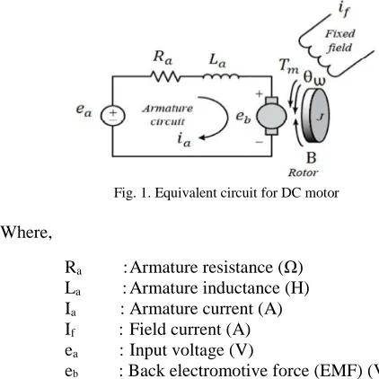
DC motor system is a separately excited DC motor, which is often used to the velocity tuning and the position adjustment. The equivalent circuit of the DC motor using the armature voltage method.
Fig. 1. Equivalent circuit for DC motor
Where,
Ra : Armature resistance (Ω)
La : Armature inductance (H)
Ia : Armature current (A)
If : Field current (A)
ea : Input voltage (V)
Tm : Motor torque (Nm)
Ω : An angular velocity of rotor (rad/s) J : Rotor inertia (kgm)
B : Friction constant (Nms/rad) Kb : EMF constant (Vs/rad)
KT : Torque constant (Nm/A)
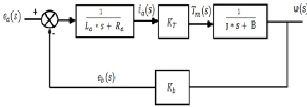
The functional block diagram of a DC motor armature voltage control system
Fig. 2. DC motor armature control system block diagram
The transfer function of DC motor speed with respect to the input voltage can be written as follows:-
b) PID control system
The development of PID control theories has already started in early sixties. PID control has been one of the control system design method of the longest history. PID controller is mainly to adjust an appropriate proportional gain (Kp), integral gain (Ki), and differential gain (Kd) to achieve the optimal control performance. The relationship between input e(t) and output u(t) can be formulated in the following,
A general closed loop control system block diagram is shown in Figure 3 as below:
Fig. 3. Closed loop system block diagram.
II. RESEARCHMETHODOLOGY
Fig. 4. Flow chart for the system
A. Conceptual Design
DC motor appliances will be used to attach to the trishaw. The input to the controller is pulse output from rotary encoder that will be attach to the paddle of trishaw.
Pulse output from rotary encoder will be used to measure current and desired speed of the trishaw. DC motor will recover the speed of the trishaw if
load disturbance or passenger weight variation is applied by using PID controller.
Testing Closed Loop System with Load PID Closed Loop System Analysis
Open Loop System Analysis
No Yes
Yes Compare Desired Speed with Actual Speed in RPM
Y es
No Tuning
Optimum PID Value controller
Take result and analysis
END
START
Testing Open Loop System with load
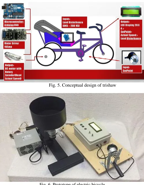
Fig. 5. Conceptual design of trishaw
Fig. 6. Prototype of electric bicycle
Figure 6 illustrates the component assembly on prototype of trishaw. The main actuator is DC motor with ratio 14:1.It comes with encoder use for detect the velocity or speed of the motor. The rotary encoder react as input for the controller.
B. DC Motor Specification
Fig. 7. DC Geared Motor (42mm) 14:1
Table I Motor Specification
C. Rotary Encoder
This encoder is the most common and accurate way of providing feedback to the controller. Shaft encoder come in many forms and sizes, but they totally rely on the same rule. For this task, an encoder is used to record the actual speed perform for the motor. The encoder will give a feedback to the PID controller to send a recent error made of the DC motor. The PID controller will give optimize output to drive the DC Motor by adjusting duty cycle of PWM in order to achieve the desired speed rate.
Fig. 8. Rotary encoder connection to Arduino
Table II
Motor Encoder technical specification
Black Motor Terminal
Red Motor Terminal
Brown Hall Sensor Vcc
Green Hall Sensor GND
Blue Hall Sensor A output
Purple Hall Sensor B output
Fig. 9. Two output from rotary encoder represent two square wave in rotary encoder
Voltages 12VDC
Rated Torque ~6.526 kg.cm (0.64 N.m) Rated Speed 405 RPM Rated Current 5500mA
Rated Power
Output 41.3W
Weight 360g
Shaft 8.0 mm diameter x 20.0 mm length
Gear ratio 14:1
Type Brushed motor type
D. Arduino UNO
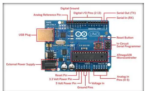
Fig. 10. Basic Configuration of Arduino UNO microcontroller
This project using Arduino UNO as a controller and PID control algorithm embedded into this hardware by using C language programming. Motor drive connected to port 5 and 6 because its provide PWM output. Port 7,8,9,10,11,12 is use to connect the LCD display. Output from rotary encoder connected to port 2 and 3 since it provide high speed Interrupt function.
III. RESULTANDDISCUSSION
A) Open Loop Analysis
Fig. 11. PWM Input vs Speed of DC Motor (Open Loop)
Figure 11 is an experiment have been take for an open loop test for DC motor speed measured based on PWM duty cycle input. The DC motor is start to rotate at 4.7 % PWM duty cycle and directly proportional until get maximum speed of the DC motor.
Next, load disturbance test with 3 difference load has been conducted to measured speed drop from 0.25 kg, 1.5 kg and 2.5 kg with difference speed. The value is choose based on the load for the DC motor. The value need to be below to the rated torque given in the data sheet to perform good response for the DC motor.
Fig. 12. Load disturbance test with setpoint 100 rpm
Fig. 13. Load disturbance test with setpoint 150 rpm
Fig. 14. Test load disturbance with setpoint 200 rpm
B) Closed Loop Analysis (Static Set Point)
In this closed loop system analysis, the PID parameter is tuning manually in prototype. The purpose of tuning the parameter is to find the optimum parameter for the PID. The good system response should be decreasing in time rising, settling time, overshoot (%) and steady state error. The Parameter is start from a minimum value Kp=0 , Ki=0 , and kd=0.Then the Kp value is start to tuning from 0.05 and Ki is tuning at 0.05 and kd is maintain to 0.The analysis is test in real application in prototype of trishaw..
Fig. 14. PID Tuning Kp=-0.050 , Ki=0.05 , Kd = 0
Fig. 15. Output for Kp=0.050, Ki=0.05, Kd=0
From the Figure 14 when the PID value is tune to Kp= 0.05 , Ki=0.05 and Kd=0.we can see that the time rising time is so slow to recovery to the set point. Furthermore, there are overshoot came to the system. The settling time also slower to recovery to the set point. The system is start to stable at 119 second. It show that the system is not stable.
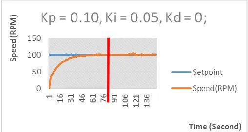
Fig. 16. PID tuning Kp=0.10 , Ki=0.05 and Kd=0
Fig. 17. Output for Kp=0.10, Ki=0.05, Kd=0
From the Figure 16 the Kp value is increase to 0.1.From the graph, the overshoot is start to decrease and rising time is decrease to 73 second. But the PID value need to be tune to decrease the rising time as short as can. The settling time is fast to stable.
Fig. 18. PID tuning Kp=0.010 , Ki=0.05 and Kd=0
Fig. 19. Output for Kp=0.010, Ki=0.05, Kd=0
Fig. 20. PID tuning Kp=0.010 , Ki=0.10 and Kd=0
Fig. 21. Output for Kp=0.010, Ki=0.1, Kd=0
From the Figure 20 the value of Kp is constant to 0.010. The value of Ki is increased to 0.10 and Kd is maintain to 0. Its shows that there is not overshoot, settling time and steady state error. The rising time is also decrease to 30 second.
Fig. 22. PID tuning Kp=0.010 , Ki=0.3 and Kd=0
Fig. 23. Output for Kp=0.010, Ki=0.3, Kd=0
From the Figure 22 the value of Ki is increase to 0.3 and Kd is maintain to 0. The result show that there were no overshoot, settling time and steady state error. The rising time is is minimize to 8 second. The system start to produce a good response for the DC motor.
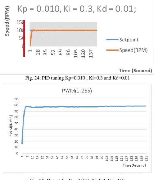
Fig. 24. PID tuning Kp=0.010 , Ki=0.3 and Kd=0.01
Fig. 25. Output for Kp=0.010, Ki=0.3, Kd=0.01
Fig. 26. Summarize of experiment take out to find optimum parameter for PID controller
Figure 27, 28, 29 below that three difference load is apply to the PID controller. It show that maximum load get higher PWM. This is because when the load is apply in increasing order, the current drive also will increase. The output will constant when the input is achieved to the set point of the cycle.
Fig. 27. Closed loop test with load disturbance 0.25 kg
Fig. 28. Closed loop test with load disturbance 1.5 kg
Fig. 29. Closed loop test with load disturbance 2.5 kg
C) Dynamic Set Point Value(Dynamic Set Point)
For real implementation in prototype, the paddle rotation speed is use as desired set point of the system. Paddle rotation speed is possible to rotate at constant speed by trishaw rider. When the trishaw rider is start to rotate the paddle, the DC motor will follow the speed set point from speed rotation of the paddle. In this analysis, system has been tested using 2 optimum parameter for PID controller that obtain in the closed loop experiment previously.
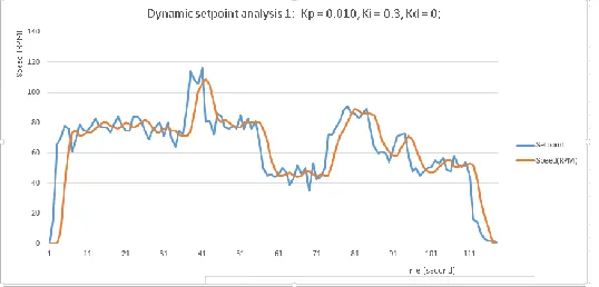
Fig. 30. Dynamic set point analysis 1, Kp=0.010,Ki=0.3 , Kd=0
Fig. 31. Output value for Kp = 0.010 , Ki=0.3 ,Kd=0
the output graph for analysis 1 in Figure 30. The output is with 0.25KG load. The maximum output is 33.33% of the PWM duty cycle. The PWM value will increase when there are load apply to the system
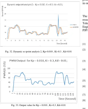
Fig. 32. Dynamic se tpoint analysis 2, Kp=0.010 , Ki=0.3 , Kd=0.01
Fig. 33. Output value for Kp = 0.010 , Ki=0.3 ,Kd=0.01
From Figure 32, by using parameter Kp=0.010, Ki=0.3 and Kd=0.01, the system response is better from previous experiment. Figure 33 show the output graph for analysis in Figure 32. The output is with 0.25 kg load. The maximum output is 33.33% of the PWM duty cycle.
IV. CONCLUSIONS
According to an experiment result, this project aimed to design a closed loop system for DC motor using PID controller consider successful. From the result, it shows that the optimum value for PID parameter for the design system is Kp=0.010 , Ki=0.3 and Kd=0.01. It show that the time rising (tr), time settling (ts), overshoot (%) and steady state error has
been minimize for the system. To get the better result, the using of another control method such as Fuzzy Logic Control, and other tuning method of PID can be used. In order to improve computational processing speed, proposed to use high speed processing controller such as FPGA or single board computer (SBC) for better computational result and response.
For real trishaw implementation, a good mechanical design must be consider in order to obtain the desired speed rate. Since that there will be a variation of load passenger weight and road surface area especially when riding at the slope area, an adaptive PID control must be consider with a high speed processing controller. An optimization technique can be apply in order to obtain an optimum value of controller.
V. ACKNOWLEDGMENT
The authors would like to thank for the support given to this research by Ministry of Higher Education Malaysia, Universiti Teknikal Malaysia Melaka (UTeM) and Faculty of
Engineering Technology (FTK) under
PJP/2015/FTK(29A)/S01454 project.
VI. REFERENCE
[1] I. S. Fatah, “PSO-BASED TUNNING OF PID CONTROLLER FOR SPEED CONTROL OF DC MOTOR,” vol. 07, no. 03, 2014. [2] M. H. Kumar, P. M. J. Sathavara, P. G. S. Automation, and C. P.
System, “COMPARISONS OF SPEED CONTROL OF DC MOTOR USING PID- PSO AND FUZZY-PSO TECHNIQUES,” vol. 2, no. 9, pp. 1847–1852, 2015.
[3] C. S. Linda, “Analysis and Design of Conventional Controller for Speed Control of DC Motor -A MATLAB Approach,” vol. 5, no. 2, pp. 56–61, 2015.
[4] V. Singh and V. K. Garg, “Tuning of PID Controller for Speed Control of DC Motor Using Soft Computing Techniques – A Review,” vol. 9, no. 9,
pp. 1141–1148, 2014.
[5] P. S. Vikhe, N. Punjabi, and C. B. Kadu, “DC Motor Speed Control Using PID Controller In Lab View,” no. 3, pp. 38–41, 2015. [6] M. Jaiswal and M. P. H. O. D. Ex, “International Journal of
Advanced Research in Speed Control of DC Motor Using Genetic Algorithm Based PID Controller,” vol. 3, no. 7, pp. 247–253, 2013. [7] I. S. Fatah, “PSO-BASED TUNNING OF PID CONTROLLER
FOR SPEED CONTROL OF DC MOTOR,” vol. 07, no. 03, 2014. [8] M. Jaiswal and M. P. H. O. D. Ex, “International Journal of
Advanced Research in Speed Control of DC Motor Using Genetic Algorithm Based PID Controller,” vol. 3, no. 7, pp. 247–253, 2013. [9] M. H. Kumar, P. M. J. Sathavara, P. G. S. Automation, and C. P.
System, “COMPARISONS OF SPEED CONTROL OF DC MOTOR USING PID- PSO AND FUZZY-PSO TECHNIQUES,” vol. 2, no. 9, pp. 1847–1852, 2015.
[10] C. S. Linda, “Analysis and Design of Conventional Controller for Speed Control of DC Motor MATLAB Approach,” vol. 5, no. 2, pp. 56–61, 2015.
[11] V. Singh and V. K. Garg, “Tuning of PID Controller for Speed Control of DC Motor Using Soft Computing Techniques – A Review,” vol. 9, no. 9, pp. 1141–1148, 2014.
[12] P. S. Vikhe, N. Punjabi, and C. B. Kadu, “DC Motor Speed Control Using PID Controller In Lab View,” no. 3, pp. 38–41, 2015. [13] Shahrizal Saat, "DC Motor Speed Control Using Fuzzy Logic