Abstract— Robots developed to respond to diverse kinds of fire accidents in modern society are the robots assisting firefighters’ fire suppression efforts. In this study, we proposed a drive system capable of moving freely in indoor environment. Moreover, since they work in fire areas with high radiant intensity, their thermo performance test can be essential. To this end, we selected thermal barrier material preventing the transfer of external heat source to the robots. Moreover, we proposed thermal barrier method that can help improve firefighting robotic heat shield. Coating the robot surface with Ag paste can prevent heat transfer to the inside. We presented thermal barrier effect according to different thicknesses of the Ag coating. It is noted that secondary thermal barrier system is efficient, which employs insulation board and Ag coating insulation box capable of protecting the electronic devices of firefighting robots at a high temperature for its efficient functioning. In this study, we proposed a firefighting robot system and thermal barrier for use in firefighting robots.
Index Term— Thermal Barrier Structure, Fire Fighting Robot, Ag Coating, Crawler System, Tension Control
I. INTRODUCTION
Firefighting robots are capable of engaging in rescue work on behalf of human in the scene of a fire such as fire suppression and helping people in danger. Although human death toll and property damage have continuously happened due to fire and follow-up measures have continued accordingly, any flawless set of responsive measures have not been seen yet. The ceaselessly created toxic gas and flames in the fire scenes are serious risk factors for not only victimized people but also rescue workers.
Throughout the world, plenty of firefighting robots have been developed and utilized in rescue operations, but only playing insufficient roles. It is true that most of the robots join fire suppression outside the fire scenes or small parts inside the scenes such as observation. Moreover, firefighting robots are to be brought in fire areas difficult to access in fire scenes with relatively high radiant intensity; thus, thermo performance test is essential [1,2]. Actually, large-scale fire accidents occurred in places releasing radiant intensity, heat source and thick smoke, mounting up resultant property damage. In order to solve such a problem, firefighting robots are being developed along with heat resisting technology for self-protection against flames [3].
The robotic structure operating at a high temperature could have additional strength decrease because of exposure to heated environment [4]. To reduce such thermal strength decrease in structural material, heat resistance can be improved but,
considering the robots’ mobile performance when their weight increases, such a method could be unfavorably designed. In the heated environment unfavorable to rescue operation, to ensure firefighting robots meet the required level of performance, it is also necessary to find and develop material for external thermal barrier so that the existing metal-based structure is protected from heat source. In heat resistance designing, there is insufficient amount of information on the basic property, heat resistance characteristics, etc. of heat barrier materials. High-temperature ignition causes rapid change in thermal characteristics. For these reasons, any existing commonly utilized analyses can hardly produce precise analysis. Therefore, experimental thermal barrier characteristics test is performed to prove thermal barrier effect [6].
The firefighting robots developed this study are capable of entering inside of the most dangerous kinds of fire scenes, suppressing fire and rescuing humans. The aim of the study was placed on developing a robot that can practically replace human firefighters in its research on a drive system operable efficiently in fire environment. In addition, thermal barrier materials were selected, which could be utilized for the heat shield of rescue materials and their thermal barrier characteristics were evaluated by creating appropriate heated environment for them. By doing so, we wish to discuss thermal barrier research findings for improved thermal shield in firefighting robots.
II. PLATFORM DESIGNING OF FIREFIGHTING ROBOTS The firefighting robot developed in this study can operate at up to 700C. It has two liquid fire extinguishers and was designed to precisely hit a fire point as far away as up to 5 m. Through flame detection sensor, it can sense fire points and be controlled remotely via its camera. Moreover, thermal barrier system was applied to the heat shield coating on its outside to stand as high as 700C temperature during operation. Insulation board was utilized in its inside to protect the robotic inside from external heat. On the outside of the firefighting robot, the flame detection sensor and IR Camera are mounted. The driving part of the robot is Crawler System where steel chain was utilized for it to drive even inside of fire scenes. It was also designed to take the stairs up to engage in rescue mission inside buildings. Moreover, the firefighting robot is equipped with two independent fire extinguishers easily removable and replaceable. The fire extinguisher module mounted on the inside of the robot employed the Operation Control Unit (OCU) to allow remote spray. The spray nozzle installed on the front
Study of Mechanical Characteristics and
Thermal Barrier Coating on Firefighting Robot
Yeon Taek OH
side of the robot is attached to the Pan/Tilt Drive for users to change the spray directions at any desired angles. The fire extinguishers can spray for 2~3 minutes continuously and temporary spray is also possible with its solenoid valve to control the nozzle spray time. After spraying all of the extinguisher liquid, connect a hose to the valve on the rear side of the robot to spray firefighting water additionally.
A. Drive System Designing
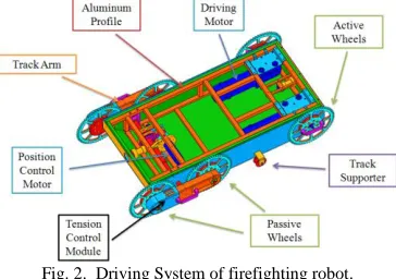
The basic frame of firefighting robot driving system is aluminum profile and a 450W DC motor was chosen as a driving motor. Since the 450W DC motor spends lots of current, lead storage battery is utilized in electric wheelchairs. However, given the size and weight of the firefighting robot, lead accumulator was difficult to apply, thus, two lithium polymer batteries were utilized in parallel connection to secure enough current.
Fig. 1. Configuration of firefighting structure.
The robot frame, aluminum profile, is light-weighted for its volume in its nature and has strong durability. It is easy to attach parts such as each motor, driving axis, camera and hardware. Assembly and matching them are also easy. In such a condition where obstacles are scattered all around, the robot may collide with them or be damaged by falling objects. In this situation, the aluminum profile also plays the role of protecting the robot’s internal system from external shock. The robot was designed to reach the max speed of 7 km/h and weigh about 90 kg.
Fig. 2. Driving System of firefighting robot.
As shown in Figure 2, two drive motors were arranged in the back of the platform for a rear-wheel drive system. Given the characteristics of track type robots, most of their weight load is concentrated on the rear wheels in overcoming obstacles such as slope way and stairs. For this reason, we adopted the
rear-wheel drive system for efficient operation.
The robot has 6 sprockets and 3 sprockets are connected with one chain on each of the left and right sides. Of the 6 sprockets in total, the frontal 4 sprockets are passive type connected to the front wheel axis and the two in the rear are connected to the drive motor, the rear wheel axis. 2 sprockets attached to the front wheel axis are designed to be utilized for obstacle overcoming.
B. Design of Obstacle Overcoming System
As firefighting robots operate in the scenes of fire accidents, many obstacles are scattered around. Moreover, in the case of building structures, stairs pose difficulties in their continued operation. An additional module is necessary to overcome obstacles as high as at least 20 cm. Since the track height is 26 cm, obstacles taller than 13 cm should be climbed up using the frictional force with the ground. But it is not easy to do so if sufficient frictional force is not secured depending upon given conditions. For this reason, we added a transformable crawler system to push the track to climb up on such obstacles.
Fig. 3. Transformable crawler system (TCS).
As in Figure 3, the two sprockets attached on the front of the robot are connected with track arm. The track arm is bilateral symmetric to move its left and right sides in the same angle all the time. Track arm movement lifts up the two foremost sprockets simultaneously to overpass an obstacle. The robot driving system is characterized as Transformable Crawler System (TCS). TCS changes track forms based on single track and can overcome obstacles solely by track transformation without needing any assistance of secondary track. So TCS is structurally simple and easy to operate. Figure 3 shows track transformation in line with topography change.
The firefighting robot’s transformation module is driven by one 50W DC motor. Since the transformation is proceeded slowly, it requires the velocity of about 1 rpm. On the other hand, it also needs large torque sufficient to lift up 50% of its weight. The torque upon the gear head is so heavy to require an industrial planet gear. Since industrial planet gears, however, are large and heavy, they affect general robot designing. For this reason, Harmonic Drive was employed in this study. Harmonic drive has strong durability compared with its size and supports high reduction at a certain volume. The gear ratio of the transformation module was set at 1/5000 after three times of deceleration.
Encoder was employed to detect any change in the rotation axis even when the power is off, enabling real-time monitoring of module change during its operation. If the power is reset because of shock, precise transformation measurement is possible. A user can enjoy easy operation as he or she can control the robot remotely and see its transformation change amount in real time.
C. Track belt designing
The track of firefighting robot must not be deformed at 700C and be able to drive through by overcoming obstacles. Thus, any normally-utilized rubber or urethane track belt cannot be utilized. We employed steel chains for the robot and utilized heat resistant rubber attachments to help reduce robot operational noise or obstacle overcoming. The attachments are consumable and removable to be assembled to the chain with bolts
Fig. 4. Tension control mode and chain.
Sprockets that drive the chain were made of 70 series with stronger durability compared with aluminum. As a firefighting robot changes its posture by turning the track arm, the overall track length changes to break or loosen the chain. For this reason, an additional module is necessary, which can adjust chain tension all the time. As shown in Figure 4, a tension control spring was installed in the space between 2 sprockets of the passive axis so that the chain tension is maintained constantly even after posture change.
III. FIRE EXTINGUISHER SPRAYING DEVICE DEVELOPMENT
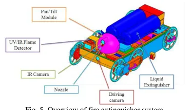
Fig. 5. Overview of fire extinguisher system.
The most important system of firefighting robots is fire extinguisher spraying device. The purpose of firefighting robots is for users to find a fire point in a remote manner and extinguish a fire. Thus, it is important for them to detect an ignition point and spray fire extinguisher liquid at a precise point. The firefighting robot developed in this study is equipped with 2 liquid fire extinguishers, a nozzle capable of spraying to a precise location, as well as a pan/tilt module that moves the nozzle up/down/left/right. Moreover, a UV/IR flame detection sensor was attached to the robot front, which can precisely sense fire points difficult to spot in camera images.
A. Removable fire extinguisher and pan/tilt module
The fire extinguisher of firefighting robot can provide safe fire extinguishment only when the spray distance exceeds at least 3m. Since robot availability increases as spray time is longer, we selected a fire extinguisher satisfying both requirements. In order to improve spray system precision, a pan/tilt module was attached, which can move the nozzle up/down/left/right. On top of the pan/tilt module, IR camera and spray nozzle are mounted for precise calibration so that a user can spray fire extinguishment liquid toward a fire point without moving the robot body. Since its nozzle and hose are the only things that move with the extinguishers being fixed onto the body, the pan/tilt payload can be set at a low level. However, as there could possibly be large force due to spray reaction, we set the final payload at 5 kg.
Fig. 6. Nozzle pan/tilt system.
The pan/tilt module case is in a sphere form capable of sealing regardless of spin directions and was designed to shield from external heat. Case material is aluminum with thermal barrier Ag coating on its surface.
B. Development of fire extinguisher liquid auto spray device
Normal fire extinguishers can be hardly workable in firefighting robots because fire extinguishment device has to be operated under remote control. But we designed the robot to accept normal fire extinguishers by employing a system with a solenoid valve to turn on/off the nozzle. With the fire extinguisher’s hose being connected to the solenoid valve, push the handle and fix it to make it all ready. Since the two fire extinguishers are connected through the solenoid valve, there must be two extinguishers mounted on in use to prevent the liquid from permeating inside the robot
Fig. 7. Nozzle Structure of fire extinguisher.
C. Flame detection sensor
points. It precisely senses UV and IR from flames and divides into multiple grades according to flame degree and certainty. A user can remotely monitor sensed values in real time through OCU
IV. THERMAL INSULATION STRUCTURE COVER DESIGNING As firefighting robots operate in fire scenes, they need to be protected from flames and high temperature. For this reason, thermal barrier system is also necessary in addition to ordinary cover. Although the robot of this study was designed to stand as high as 700C environment, the electronic device in its inside could malfunction at 60C or higher because of heat. Therefore, it is important to keep its internal temperature not higher than 60C.
Thermal barrier system should be applied to not only the overall cover of the robot, but additionally the case of flame detection sensor and camera protruding outwards to ensure effective operation under remote control manipulation.
A. Camera case designing
Fig. 8. Thermal protection structure of camera.
Each camera lens is exposed to the outside, so its thermal barrier is impossible without using an additional module. If heat penetrates inside of the camera through glass, the camera is damaged. In this respect, we designed a heat barrier module using Quartz lens which is both transparent and highly heat resistant. Considering the camera viewing angle, we arranged Quartz lenses in three layers and had air layers in between to prevent heat conduction. The CCD camera utilized in the front and rear has only the single feature of waterproof. The aiming camera installed on the nozzle was chosen as the product with IR LED in addition to the waterproof feature so that it can precisely aim even in a dark place.
B. Flame detection sensor case designing
Fig. 9. Thermal protection structure of frame detector.
Flame detection sensor, just as the cameras, has a glass frontal part. Since they sense UV and IR entering through the glass window, they need a transparent thermal barrier module. The thermal shield module utilized in flame detection sensor is also the three layers of Quartz lenses inside an aluminum case.
V. EXPERIMENT ON FIREFIGHTING ROBOT’S THERMAL BARRIER AND COVER DESIGNING
A. Thermal barrier test of Ag Paste coating film
For the thermal shield of firefighting robot, we applied Ag paste (DS-PF-7185) on one side of the Al plate exposed to heat source then let it dry at room temperature for 1 hour naturally before putting in the oven at 80C for 1 hour. The Al plate spread with Ag paste was placed under heat treatment at 350C for 10 minutes. As in Figure 10, the coated robot body was installed in an electric furnace. With the furnace open, the internal temperature was 550C and the temperature of heating element on the wall side of the furnace was measured 720C. To measure the internal temperature of the body, we installed thermocouple at the center of the body as in Figure 10 and measured the internal temperature
Fig. 10. Heat Resistance Test of Al plate.
After the heat barrier experiment, the Al plate was found to have no deformation. However, in some areas where the applied coating film was thinner, Al plate surface was partially exposed as organic component contained in Ag plate had been decomposed under heat treatment. The internal robot body temperature also rose up to 400C in 1 hour. The Ag paste coating was found as effective thermal barrier.
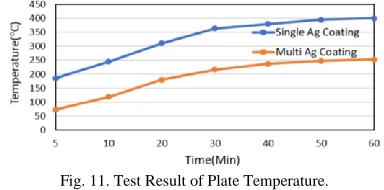
Fig. 11. Test Result of Plate Temperature.
In order to investigate the thermal barrier effect according to coating film thickness, the Ag paste was secondarily coated on to the Al plate, then a thermal barrier test was conducted. The coating and experimental method were identical to those in the first experiment. As in Figure 11, thanks to the secondary Ag paste coating effect, the internal temperature dropped from 400
C to 253C in 1 hour. The experiment found that heat shield was effective depending upon the Ag paste coating film thickness. In the first test, the coating application thickness was uneven and partial plate surface was uncovered as organic component contained in the Ag plate had been decomposed. However, the secondary coating film was evenly applied, allowing no plate surficial transformation.
body. However, the electronic device inside firefighting robot cannot maintain its electronic parts features for a long time at approximately 250C, the internal temperature of secondary test. To protect the electronic device from heat source, we employed an internal box coated with Ag to provide dual-thermal barrier structure.
Fig. 12. Coating Surface & Thickness.
B. Sil-tex thermal barrier test
After applying the dual-thermal barrier structure to electronic device, we implemented the secondary thermal barrier experiment with a view to applying Sil-tex where Silica, heat proof fiber, was woven in. Sil-tex, high temperature exceeding 1,700C are composed of continuous filament Sil-tex and specially design to replace asbestos in varieties of high heat application. It is widely used in modern industrial fields with its own excellent advantage. Sil-tex has properties as shown in table 1.
TABLE I PROPERTIES OF SLILCA.
Specific gravity
Tensile Strength
(Kg)
Continuous Workable
Temperature (C) Point(C) Melting
Silica 2.4 210 1093~1704 1704
The experiment was implemented in the identical method and procedures to those in the previous section. The temperature of internal box was measured, in which the electronic device was to be installed. In the dual-thermal barrier structure, Sil-tex was utilized to the outside and inside of the robot cover and internal box in the thermal shield test. As in Figure 13, Sil-tex was applied in diversified manners in the experiment. As in Figure 13(a), when Sil-tex was applied to the cover outside, the temperature was about 190C on the inside. Figure 13(d) shows that when Sil-tex was utilized in the Ag-coated robot cover and Ag-Ag-coated internal box, the internal temperature was 83C. As a result of the experiment, as shown in Figure 13(d), the most effective thermal barrier combination was Ag-coated cover and Sil-tex-woven internal box. Figure 14 shows internal box temperatures of each diverse Sil-tex application cases.
(a) (b) (c) (d)
(a) Sil-tex Cover, (b) Ag coated Sil-tex cover, (c) Ag coated Sil-tex cover & inside Sil-tex, (d) Ag coated cover & inside Sil-tex
Fig. 13. Heat Resistance Test of Sil-tex.
Fig. 14. Test Result of Sil-tex.
C. Insulation board test
Ag coating film and Sil-tex were found effective in controlling temperature increase inside the robot body. However, the internal temperature of 83C seems to pose difficulty for the long-term continuance of electronic device functioning. Therefore, we conducted a thermal barrier experiment for the insulation board that could complement the Sil-tex. A secondary thermal barrier system employing an insulation board was installed on the inside of the electronic device. After fixing the insulation board on the inside of Ag-coated Al box, the electronic device was placed.
Fig. 15. Insulation Board Test.
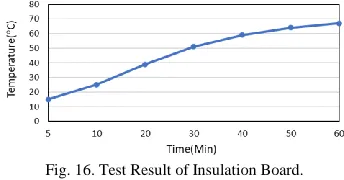
Figure 15 shows that the secondary thermal barrier system employed the insulation board. In the thermal barrier test, as shown in the figure, the Ag-coated Al plate was spaced from the secondary thermal barrier system to control the internal temperature rise due to heat transfer to the maximum possible extent. The thermal barrier test was implemented in the structure shown in Figure 15 for 1 hour in an electric furnace. The experiment found the results of internal temperature measurement of the secondary thermal barrier system as displayed in Figure 16.
Fig. 16. Test Result of Insulation Board.
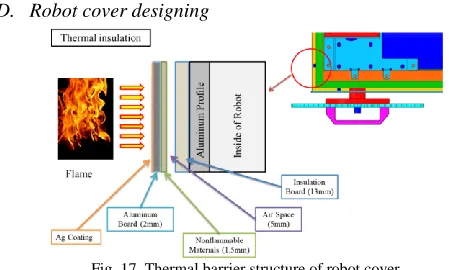
D. Robot cover designing
Fig. 17. Thermal barrier structure of robot cover.
The external cover of firefighting robot is 2mm thick aluminum which cannot shield from 700C temperature and flames. For this reason, we introduced the thermal barrier structure proposed in the thermal barrier experiments. First of all, excluding the Quartz lens, all of the robotic external cover was coated with Ag. Since Ag has excellent reflexibility, the robot can reflect out the radiant heat from heat source. As in Figure 17, flame-resistant Sil-tex and insulation board were utilized in the space between the aluminum plate and internal aluminum profile frame. Sil-tex is attached to the inner side of aluminum plate in three layers with 5 mm spacing from the insulation board to allow air layers. Air layers play an important role of preventing thermal transfer. Lastly, a 13.5mm-thick insulation board was applied to the final layer. As insulation board can be processed and tailored, we processed it in the case form and attached to the entire profile to provide thermal shield. Figure 18 shows the overview of the Ag-coated firefighting robot.
Fig. 18. Overview of firefighting robot.
VI. CONCLUSIONS
Through experiments, we made the thermal barrier system of firefighting robot protect the robotic inside and support operation at high temperature. Moreover, by applying sensor and Crawler System to the outside of the robot, we made it possible for the robot to efficiently drive around and climb over inside a fire scene to pursue rescue work.
It is noted that the thermal barrier system to protect the internal devices of firefighting robot prevents heat source and flames delivered to the robot from outside and the Ag coating is effective in reinforcing heat resistance to protect the main body. Furthermore, it was also found that the Ag-coating on the surface of robot cover could prevent heat penetration to the inside and the thicker the coating film, the more effective it is. The dual structure based on internal box is found effective for thermal barrier system, which can protect the electronic device inside of firefighting robot from high temperature while ensuring its efficient operation. It was also found effective to
space and install the thermal barrier system for the maximum suppression of thermal transfer.
ACKNOWLEDGEMENT
This Research was supported by the Tongmyong University Research Grants 2018 (2018F005) and This work was supported by BB21+Project in 2018.
REFERENCES
[1] M. Kazuyoshi, “Fire robots developed by the Tokyo Fire Department” Advanced Robotics, Vol. 16, No. 6, pp. 553-556, 2002
[2] J. H. Kim, C. K. Hwang & K. B. Lee, “Thermal Resistance Characteristics of Thermal Resistance Materials Exposed to Heating Environment”, Proceedings of International Journal of Aeronautical and Space Sciences, KSAS08-1103, 2008
[3] J. Bae, K. H. Chung, W. S. Choi & S. H. Kim, “Experimental Approach to Assessment of Adhesion Characteristics of Thermal Barrier Coatings”, Proceedings of the Korean Society of Precision Engineering Conference, 2016
[4] Buchanan, A. H., “Structure Design for Fire Safety”, John Wiley & Sons, 2001
[5] J. H. Kim, K. Bhum & J. H. Kim, “Tensile Behaver of 17-4PH Stainless Steel under Rapid Heating”, Key Engineering Materials, Vol. 297-300, pp. 1482~1488, 2005.
[6] Chan-Won Kwak, “Thermal Coating Technology and Application Status”, Ceramist. Vol. 19, No. 3, pp. 46~56, 2016.
[7] Clarke, D. R., M. and Padture, N. P., “Thermal-Barrier Coatings for More Efficient Gas-Turbine Engines”, MRS Bull, No. 37, pp. 891-898, 2012. [8] Y. T. OH, “Study of Unmanned Ground Vehicle Platform to Overcome
Vertical Obstacle”, J. Korean Soc. Mech. Tech., Vol. 17, No. 4, pp. 727~732, 2015