Abstract- Fractal antennas have the potential to provide multi-band solution through the property of self-similarity that fractal shape possess with fairly good radiation pattern at different resonance frequencies. An analysis is performed to examine the multiband behavior of Sierpinski Triangular Gasket Patch Antenna up to frequency range of 15GHz. Analysis of parameters of triangular patch antennas for various dimensions is calculated and furthermore these results are compared with the Sierpinski patch antenna’s multiband behavior and radiation pattern. Additionally a technique to enhance the multiband behavior of Sierpinski patch antenna has been used by placing a triangular grid on top of it. A direct coaxial feeding technique is used near the vertex of the triangular geometry. Feed position optimization is not considered. The behavior of antennas are investigated such as return loss, radiation pattern, current distribution, total E field vector. Ansys HFSS software has been used to simulate the geometry and satisfactory results are presented.
Keywords – fractal antenna; Sierpinski triangular gasket; return loss; multiband; triangular patch antenna
I. INTRODUCTION
Fractal geometry is an expansion of Euclidean geometry. It has two properties: space-filling and self-similarity. Self-similar objects look roughly the same at any scale. Thus, in an antenna with fractal shape, similar surface current distribution is obtained for different frequencies i.e. multiband behavior is provided. The space filling property leads to curves that are electrically very long, but fit into a small physical space. Instead of using multiple radiating elements of conventional microstrip patch antenna to achieve multiband behavior, one can simply use fractal antenna to achieve the same along with the advantage of reduced size [4]. Broadband operation is becoming increasing popular in many practical applications. One such geometry is the Sierpinski triangular gasket. Waclaw Sierpinski described the Sierpinski Gasket in 1915, and it became an important part of fractal set.
The Sierpinski monopole antenna shows better multiband behavior than Sierpinski patch antenna [8], but the monopole antenna is difficult to mount on wireless equipment because of its protruding nature. Patch antenna being planar can be fabricated on circuit boards. In this paper, I have limited the scope of my analysis to Sierpinski patch antenna and accepted the results from [8] for monopole antenna’s multiband behavior.
II. ANTENNA DESIGN AND ANALYS
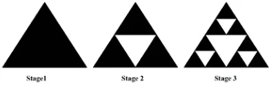
Sierpinski triangular gasket antenna is a fractal antenna. It consists of inverted triangles ½ the side of the previous stage being cut, creating triangular shaped holes. Ideally, fractal shapes are self-similar to infinity, but practically we have to limit it to a particular stage. First 3 stages are shown in Figure1.
Figure 1. Scheme of three stage Sierpinski gasket antenna
Figure 3. Designed Sierpinski Triangular antenna
If one neglects the center holes, antenna performance similar to three-scaled triangular patch antenna can be expected. Resonant frequencies are those frequencies around which power is radiated efficiently.
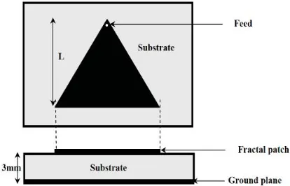
Figure4 shows a triangular patch antenna of Length L, where L is the length of each sub-gasket i.e. 11mm, 22mm and 44mm. The selected substrate here is Rogers RT/duroid İU WDQ ZLWK WKLFNQHVV
t=3mm and ground plane of 100mm x 100mm for all designs. The antennas is fed near the vertex of the triangular geometry using a coaxial feed with outer radius 1.08mm and inner radius 0.125mm separated by an insulaWLRQİr=6.6).
Figure 4. Top and side view of the Triangular patch antenna
III. SIMULATION RESULTS
Figure 5. Return Loss vs Frequency for 11mm Triangular patch
Figure 6. Current distribution at the chosen solution frequency of 10.8GHz
Figure 7. Radiation pattern at 10.8GHz
Figure 9. Total E field vector at the chosen solution frequency of 10.8GHz
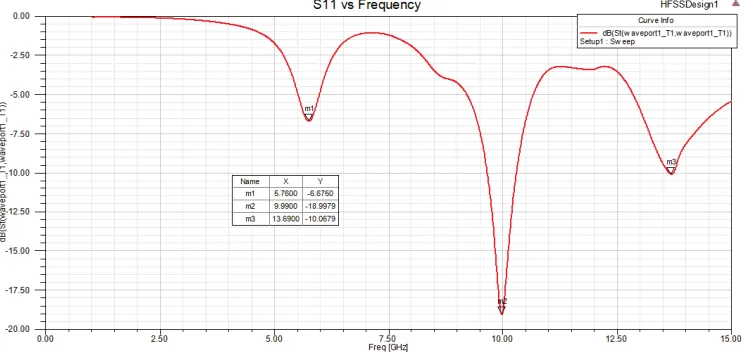
For the second triangular sub-gasket of L=22mm and side of the equilateral triangle S=25.4034, feed position offset by 1mm from the top vertex of the triangle. The solution frequency chosen was 7.8GHz. The results of the simulation are presented in figure10 through figure14. From figure10, we observe three resonances at 5.76GHz, 10GHz and 13.69GHz
Figure 10. Return Loss vs Frequency for 22mm Triangular patch
Figure 11. Current distribution at the chosen solution frequency of 7.8GHz
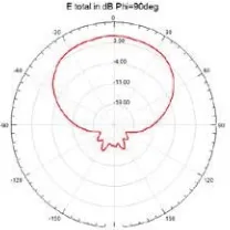
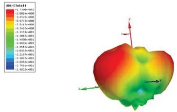
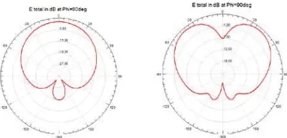
Figure 12. Radiation pattern at 5.76GHz, 10GHz and 13.6GHz respectively
Figure 13. Overall radiation pattern at the chosen solution frequency of 7.8GHz
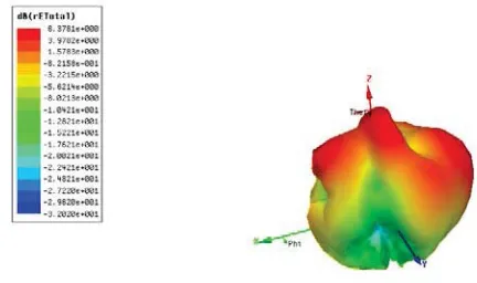
Figure 14. Total E field vector at the chosen solution frequency of 7.8GHz
Figure 15. Return Loss vs Frequency for 44mm Triangular patch
Figure 16. Current distribution at the chosen solution frequency of 6.3GHz
The first resonance is due to the propagation of the first mode whereas the others are due to different higher mode propagation. It is seen from figure17 that as higher order modes start to propagate, the main lobe in the radiation pattern doesn’t remain smooth and has a notch in the center.
Figure 18. Overall radiation pattern at the chosen solution frequency of 6.3GHz
Figure 19. Total E field vector at the chosen solution frequency of 6.3GHz
The 2ndstage Sierspinski antenna was designed in a way similar to triangular patch antennas as shown in figure20
Figure 20. Top and side view of the Sierpinski Triangular patch antenna
The height of the Sierpinski fractal is chosen as 44mm based on fractal used on the literature [1,3].
Figure 21. Return Loss vs Frequency for 44mm Sierpinski Triangular patch
In figure22, it can be seen that using a Sierpinski patch antenna, we get fairly smooth radiation patterns at different resonant frequencies, as it acts like triangular patches of different lengths resonating simultaneously with their first mode of propagation dominating. Thus providing good multi-band behavior.
Figure 22. Radiation patterns at 4.81GHz, 5.64GHz, 9.79GHz and 11.84GHz respectively
Figure 24. Total E field vector at the chosen solution frequency of 10.3GHz
Figure 25. Current distribution at the chosen solution frequency of 10.3GHz
We would expect the characteristics of fractal Sierpinski patch antenna to inherit the behavior of the three scaled triangular patch antennas. As can been seen from the results, the Sierpinski patch resonates at fewer frequencies as compared to the various triangular patches which are scaled by a factor of 2.
The Sierpinski monopole resonates at more frequencies compared to patch as shown in literature [8]. The reason for this is because coupling between the triangles is very weak and that current fails to adequately penetrate into the lower triangles as seen in figure25. Only few triangles in which the current can penetrate through, resonates effectively. For effective radiation at certain frequency, the current should concentrate over the region of the structure comparable to the corresponding wavelength, which does not happen due to the weak coupling between the triangular patches [8].
From the results we can see that the Seirpinski patch antenna does not possess well enough multi-band behavior and the study on current distribution on that patch gave a clear picture on the cause of failure. Improving the coupling between the triangular patches could help in obtaining a good multiband behavior from the Sierpinski patch.
Recent development on Sierpinski patch antenna suggest adding a grid layer of 0.7mm placed above the original Sierpinski patch on a thin substrate of thicknHVV PP İ 7KHUHE\ SURYLGLQJ VWURQJHU
electromagnetic coupling between the triangular patches [8].
Figure 27. Return Loss vs Frequency for 44mm Sierpinski Triangular patch with grid
As seen from figure27, we get nine resonances at 2.24GHz, 4.79GHz, 5.57GHz, 5.85GHz, 6.07GHz, 9.55GHz, 10.42GHz, 10.89GHz and 11.63GHz. Number of resonance frequencies has increased as compared to the original Sierpinski patch. Figure28 shows the improvement in the electromagnetic coupling as more current penetrates into the lower triangles as seen in figure28.
Figure 28. Current distribution at the chosen solution frequency of 10.3 GHz
Figure 30. Overall radiation pattern at the chosen solution frequency of 10.3GHz
Figure 31. Total E field vector at the chosen solution frequency of 10.3GHz
Figure 32. Total E field vector of grid at the chosen solution frequency of 10.3GHz
IV. CONCLUSION
Computer Technology, vol. 3,pp. 386-390, 2011
[3] M. Singh, S. Diwari, N. Kumar, P. Kala, ”Bandwidth enhancement using small triangles on Sierpinski fractal,” International Conference on Signal Processing and Communication,pp. 86-91, 2013
[4] R.P. Dwivedi, D.Upadhyay, ”High gain dual band antenna using fractal geometry for mobile communication,” 2ndInternational Conference
on Signal Processing and Integrated Networks, pp. 50-55, 2015
[5] C. Puente, J. Romeu, R. Pous, X. Garcia, “Fractal multiband antenna based on the Sierpinski gasket,” Electronics Letters, vol. 32, no. 1, pp. 1-2, 1996
[6] J. Yeo, R. Mittra, “Modified Sierpinski Gasket Patch Antenna for Multiband Applications,” IEEE Antennas and Propagation Society International Symposium, vol.3, pp. 134-137, 2001
[7] C. Borja, J. Romeu, ”Multiband Sierpinski Fractal Patch Antenna”, Antennas and Propagation Society International Symposium, vol. 3, pp.1708-1711, 2000
[8] Luintel T. (2001). Modified Sierpinski Fractal antenna (Master’s thesis). Retrieved from: