e-ISSN: 2278-067X, p-ISSN: 2278-800X, www.ijerd.com
Volume 11, Issue 04 (April 2015), PP.01-06
Design of Microstrip UWB Bandpass Filter using open-circuited
resonators
S.Rabia Jebin
1, M.Shalini
2, P.Swetha
3, D.Srilekha
41
Assistant Professor, Velammal Engineering College, Chennai-600066.
2
Department of ECE, Velammal Engineering College, Chennai-600066.
3
Department of ECE, Velammal Engineering College, Chennai-600066.
4
Department of ECE, Velammal Engineering College, Chennai-600066.
Abstract:- A compact band pass filter with a fractional bandwidth of 59% is designed for Ultra Wide Band (UWB) applications using a microstrip structure consisting of open circuit resonators. Transmission zeros are utilized at the passband edges to enhance the signal selectivity. The filter is characterized by sharp roll-off characteristics due to the presence of transmission zeros. The insertion loss and return loss are found to be 0.1dB and -15dB respectively. This filter has a measured 3-dB passband of (3 to 5.5) GHz, with a compact size of (13.2 x 9.7) mm. The filter offers desirable performance for the lower-band frequency of a UWB system and exhibits low insertion loss. As the structure comprises of only transmission line sections and no coupling gap, the filter is made easy for fabrication. This UWB BPF is useful to alleviate the strong WLAN signals interference to UWB receivers. To illustrate the concept, band pass filter was designed using Agilent® ADS software and simulated results are obtained.
Keywords:- Resonators, Band pass filter, Microstrip, Transmission zeros, WLAN.
I.
INTRODUCTION
In 2002, Ultra-wideband (UWB) frequency range of (3.1-10.6) GHz was released by the U.S. Federal Communication Commission (FCC) for commercial purposes.UWB transmission is normally realized using Impulse Radio or MB-OFDM techniques. The entire UWB spectrum is divided into 4 groups using MB-OFDM technique, which are further subdivided in to 14 sub-bands. Group A consist of first 3 sub-bands operating in the frequency range of (3.1 to 4.8) GHz and group B is in the range of (4.9 to 6) GHz. In such applications, filter with required bandwidth and low insertion loss is one of the critical components. Ultra-Wideband (UWB) technology has drawn attention of researchers for high speed wireless connectivity applications.
Design of ultra wideband filters for using in wireless technology systems is mainly to transmit data over spectrum of frequency bands for short distance with very low power and high data rates As a key component of UWB communication system, the designed band pass filter should have low insertion loss over the operating band, good band rejection, which is important for many wireless applicatons.
Ultra-wideband (UWB) systems have aroused a great deal of attention and a number of UWB band pass filter design techniques have been proposed in the past year such as multi-mode resonators (MMR) [1,2].A systematic and analytical method for the exact synthesis of generalised Chebyshev wideband hybrid ring based bandpass filters with a controllable transmission zero pair was developed in [3].
A wideband bandpass filter composed of a shorted microstrip line fed by two open-ended side-coupled lines was presented in [4]. A cross-coupled wideband bandpass filter developed from a standard short-circuited stub filter with additional coupled lines was proposed in [5]..Low insertion loss microstrip bandpass filters with sharp rejection were proposed, where the direct synthesis method of elliptic function transmission-line filters was presented [6
].
A compact bandpass filter is presented for ultra-wideband (UWB) applications with a reconfigurable notched band to reject unwanted signals from the WiMAX systems [7].A wide band bandpass filter with a bandwidth 1 GHz at a mid-band frequency of 3 GHz leading to 40% FBW using two open circuit resonators was reported with a filter size of (42 X 19.2 mm) [8].
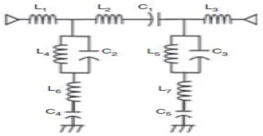
Fig. 1: Equivalent circuit of a Proposed UWB filter
A. Filter Analysis
A bandpass filter is designed with the following specifications: Centre frequency of 4.25 GHz and fractional bandwidth of 59%. The filter was designed on Taconic RF substrate with details shown in Table 1.
Table I: Substrate Details
To get the signal coupled to the other lines they have to be kept closer to each other intentionally. But, when they are kept closer unintentionally to minimize the area and to get a compact structure, it still provides coupling and results in unwanted effects.
Fig.3: Cross section of a transmission line and coupled lines
However, if the traces can be placed close to each other, the area needed could be reduced which makes the filter compact and required one. In order to make the filter layout compact, meandering of the resonator is carried out. This approach leads to a filter size of 13.7 mm x 9.2 mm. This structure is illustrated in Fig.4.
Parameters Substrate
Material Taconic RF35
Dielectric constant 3.5
Substrate thickness 0.76 mm
Fig.4: Layout of UWB band pass filter using meandered lines and resonators
The simulation was carried out using a commercially available EM tool (Advanced Design System). The final layout of the proposed filter, including the physical dimensions, is shown in Figure. 5.
Fig.5: Layout of proposed band pass filter
The two open-circuited resonators are meandered to reduce the circuit size. The optimised parameters of the filter are: L1 = 13.2 mm, L2 = 9.7 mm, L3 = 6.1 mm, L4 = 8 mm, L5 = 9.7 mm, L6 = 2.5 mm, L7 = 5.1 mm,
L8 = 2.7 mm, L9 = 1.1 mm, W1 =2 mm, W2 = 1 mm, W3 = 1 mm, S = 0.5 mm. The 3D view of the proposed
Fig. 6: Isometric view – 3D view
III.
SIMULATION
RESULTS
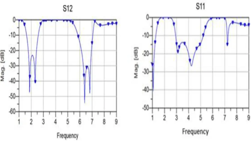
The simulated results of a typical bandpass filter centered at 4.25 GHz are shown in figure 7. The insertion loss is about 0.1 dB and the return loss is about -15 dB. The designed filter is capable of rejecting the WLAN frequencies (2.4GHz and 5.8GHz) in order to avoid interference.
Fig. 7: S12 and S11 Response using meandered lines and resonators
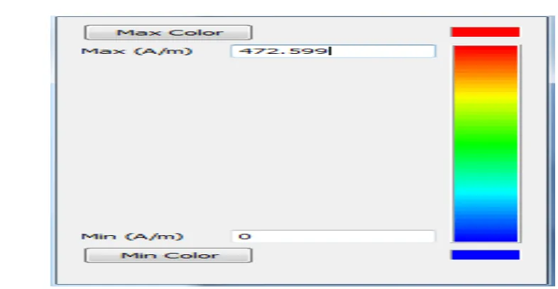
Fig. 8: Colour Bar for Average current distribution
Fig .8.1: (a) Average Current Distribution at 4 GHz (b) Average Current Distribution at 6 GHz
IV.
APPLICATION
OF
UWB
FILTERS
Filters are used in diffierent applications such as radio and television broadcasting, mobile communications, satellite communications, traffic radar, air traffic radar, automotive radar and synthetic aperture radar. In many applications. UWB filters are used to reduce harmonics and help in designing mixers, power amplifiers and voltage controlled oscillators. These are also used in removing the DC offsets and removal of low-frequency noise. UWB filters also help in separating different frequency bands like diplexers and multiplexers.
V.
CONCLUSION
pass filter design,‟ IEEE Microw. Wirel.Compon.Lett., 2010, 20, (6), pp. 322–324
[5]. Shaman, H., and Hong, J.-S.: „Input and output cross-coupled wideband band pass filter,‟ IEEE Trans. Microw. Theory Tech., 55, (12), pp.2562–2568,2007.
[6]. Lee, H.M, “Direct synthesis of transmission-line elliptic bandpass Filters”, IEEE MTT-S Int. Microwave Symp. Dig., Baltimore, MD, pp. 1–4,USA, 2011.
[7]. K. Rabbi, L. Athukorala, C. Panagamuwa, J.C. Vardaxoglou and D. Budimir, “Compact UWB bandpass filter with reconfigurable notched band”, ELECTRONICS LETTERS, Vol. 49 No. 11. [8]. Fu-Chang Chen, Jie-Ming Qiu, Zhi-Han Chen and Quig-Xin Chu, “Low Insertion Loss wideband Band
pass Filter with six transmission zeros,” IEEE Electronics Letters., vol.49 (7), 2013. [9]. Pozar D.M.: „Microwave engineering‟ (Wiley, 1998, 2nd edn.)