© 2019 JETIR May 2019, Volume 6, Issue 5 www.jetir.org (ISSN-2349-5162)
PMSG Based Wind Energy Conversion System
Containing Reactive Power Control Scheme
1
Ziyaulhaq Bokda,
2Prof.
Manish Pandya
1M. Tech Research Scholar, 2Associate Professor, PIET, Vadodara 1Parul Institute of Engineering & Technology,
1Parul University, Vadodara, India
Abstract: This paper shows the working of a reactive power management technique for network connected PMSG based wind power system with unification of WPCS to the grid-network through 3-phase AC-DC-AC converters PWM voltage source converters in order to organize volatile speed functioning of PMSG with independent reactive power support. This system is an irregular speed scheme which for PMSG. Control of the generation side converter works for control of active power or fetching best possible Power of the machine while controlling of the output side converter maintains the voltage at the DC link at constant value and it also supplies the control of reactive power to the grid. At the end, Simulink/MATLAB model run for MPPT control on machine side. Voltage control at DC-link and reactive power restrains on grid side. At last, the outputs define that the controllers are able to fetch maximum power and control the reactive power of wind generation under different wind and load conditions. Simulation was performed with a 2.68 kW DD-WT based wind energy generation system.
Index Terms- Direct Driven Permanent Magnet Synchronous Generator (DD-PMSG), Grid side converter (GSC), Machine side converter (MSC), Wind Turbine(WT), Wind Energy Conversion System (WECS), Back to back converter (BTB), Maximum Power Point Tracking (MPPT), Reactive power control, Variable speed wind turbine.
I.INTRODUCTION
Among the various resources of renewable energy, wind power sector achieved most rapidly growing sector in recent times. Wind generation system is a vital area to reducing carbon emissions. Currently, through gigantic growth in wind power generation, wind power effortlessly adapted to energy form by using of wind turbines. [1]. But, the existence of gearbox in WT that pairs the turbine to the PMSG makes difficulties. The gearbox often affected by significant problems, needs repairs and drops the total productivity of whole the system [2], [14].
PMSG has been utilized mostly in the wind power area because its benefits over others [3]. Monitored reactive power, half-scale converter and various ride through competencies are studied the prime benefit of this generation scheme [4]. Day by day, the progress in bulky wind power ability, larger the power concentration, necessity of better reliability and bad LVRT capacity of the half-scale converters, various kinds wind power schemes established.
The DD- PMSG is able to increase the reliability of wind power system. As it is beneficial to others, DD-PMSG met further interest in the current time [5]. it has additional benefits over other formations of wind energy production system like excessive power density, reduced losses, better productivity, low repairs rate there is no gearbox, slip rings and full-controlled power converters who enhances the grid capability. Direct drive functioning can be attained with noiseless operation.
Using PM in the generator rotor makes the influencing current supply through the stator needless for regular air-gap flux. The current that is in the stator essential for barely generating the torque in PMSG. Hence, for the similar output, the machine will work with better power factor and will be better over other generators.
Some Scholars are working to develop various schemes for MPPT control of PMSG so that best possible power can be transmitted to DC Link from the source of the system. Various kinds of regulation techniques like duty cycle scheme, optimum relationship-based method, look-up table for maximum speed of machine rotor, optimal control of the torque and power, optimal TSR, Perturb & Observe and peak climb searching control etc. suggested for optimum wind energy generation. To fetch the best possible output from flexible wind velocity operation in WECS is essential. The general control schemes of maximum power chasing needed to attain optimal wind power consumption.
The DD-PMSG, based wind power system contains a machine coupled directly to wind turbine. The machine stator coupled to the full scale AC-DC-AC converter and VSC is linked to the power grid/loads to acquire the amplitude and frequency necessities. Wind power system with BTB converters chosen nowadays, as the power converters fully delinked the generation from grid disturbances.
II.PMSGMODELANDCONTROL
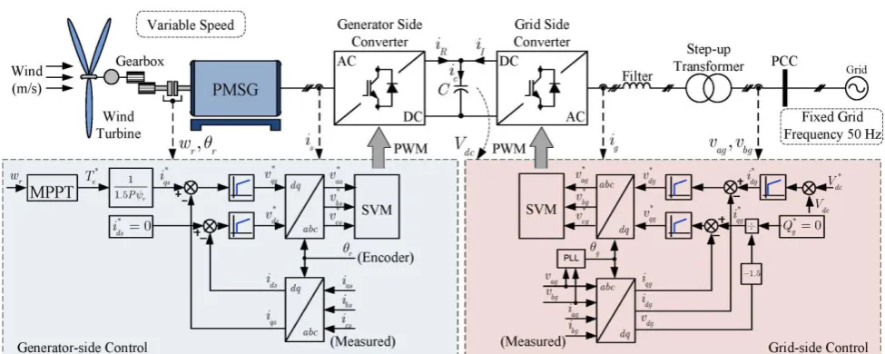
A voltage source converter based PMSG wind turbine have few parts i.e. a direct-driven WT, a PMSG, and converters as shown in Fig. 1 [7], [14]. In the WECS, the turbine draws wind power which supplied to the PMSG. A completely controlled
converter interfaced among generator and grid to decouple them. SPWM scheme applied for switching the BTB converters: a generator side converter, and a load side inverter, having voltage at dc link voltage amongst it [8], [9].
The generator control system has two segments: the PMSG and the WT part. At the PMSG side, BTB converters are regulated by the regular control theme. The generator side converter is regulated by means of speed adjustment to fetch the optimal power production from turbine.
Conventional Proportional and Integral control applied to produce torque reference. The GSC sustains the voltage at dc-link unvarying and maintain the reactive power. At the generation part, a speed controller and a torque controller applied. Here, at minimal wind flow velocity, the speed controller offers a power or a torque constant at the generator side controller founded over MPPT. The power controller rises or cuts the pitch angle of turbine blades for the purpose of protection of the WT over evaluated power at huge wind speed conditions [11], [21].
III.MODEL OF PMSG WIND TURBINE 3.1 Shaping the Wind Turbines
The WT power dragged by a turbine is stated by the following equation [14].
𝑃
𝑚= 0.5𝐶
𝑝(𝜆, β) 𝜌
𝑎𝑖𝑟𝐴
𝑏𝑙𝑎𝑑𝑒𝑣
3𝑤𝑖𝑛𝑑(1)
Here 𝑃𝑚 is mechanical power related to the power fetch from the wind by blades, 𝐶𝑝, is the power coefficient and 𝜌𝑎𝑖𝑟 is density air in kg/m3 which is about 1.225 kg/m3, 𝐴
𝑏𝑙𝑎𝑑𝑒 gives the covered area by blades of the rotor [m2] and 𝑣𝑤𝑖𝑛𝑑is the speed of wind (m/s).
The 𝐶𝑝 is a related with the pitch angle β and of the TSR (λ) . The TSR λ is the ratio of tip speed of blade and 𝑣𝑤𝑖𝑛𝑑 value, given by
𝜆 =
𝜔𝑚∙𝑅𝑣𝑤𝑖𝑛𝑑
(2)
In this Equation, R is the blade radius and 𝜔𝑚 is the rotor speed. The 𝐶𝑝 displays the power fetching efficiency of the WT. It is a nonlinear link to λ and the pitch angle. The max calculated value of power coefficient is 0.59, but practically it lies around 0.4 to 0.45. There are many equations for power coefficient in different literatures. One of them used to model Cp (λ, β) and based on the modelling the WT characteristics. The Cp (λ, β) expressed through TSR and the pitch angle.
λ 6 c λ 5 c e 4 c β 3 c λ 2 c 1 c λ, p C
(3)
And
,
1𝜆
=
1 𝜆+0.08𝛽
−
0.035
© 2019 JETIR May 2019, Volume 6, Issue 5 www.jetir.org (ISSN-2349-5162)
Figure 2 Cp by λ curve Figure 3 Turbine power vs speed characteristics
The values of constants c1 to c6 are defined as C1=0.5176, C2=116, C3=0.4, C4=5, C5=21 and C6=0.0068. The optimal power is calculated by the coefficient 𝐶𝑝 if wind speed 𝑣𝑤𝑖𝑛𝑑 is known. Generally, the 𝐶𝑝 is related with λ which expressed in equation (3).
The WT graphs of Pm to power coefficient and TSR and Turbine power by speed curves as shown in Fig. 2. And above statement describes the values of the 𝐶𝑝 constants. The WT power is found by the Cp and TSR for fixed value of the blade covered area, air density, and wind speed. The power conversion coefficient and the TSR depend on the aerodynamic curve of the WT. The optimum turbine power lies at a point of 𝜆𝑜𝑝𝑡 and 𝐶𝑝𝑚𝑎𝑥 as shown in Fig. 3.
3.2 Modeling of PMSG
The equations for voltage at stator transient using generator convention in the synchronous reference frame are,
(𝑉𝑉𝑑 𝑞) = −𝑅𝑠( 𝑖𝑑 𝑖𝑞) − 𝑑 𝑑𝑡( 𝜓𝑑 𝜓𝑞) + 𝜔𝑒( 0 −1
1 0 ) (
𝜓𝑑
𝜓𝑞) (5)
where 𝑅𝑠 is the resistance of stator winding, 𝑉𝑑,𝑉𝑞,𝑖𝑑,𝑖𝑞,𝜓𝑑 and 𝜓𝑞 are the stator voltages for direct and quadrature axis components, current of stator and flux of generator. If the rotor flux is aligned with d-axis then the stator flux linking shown follows,
(𝜓𝜓𝑑
𝑞) = (
𝜓𝑓
0) + (
𝐿𝑙𝑠+ 𝐿𝑑𝑚 0
0 𝐿𝑙𝑠+ 𝐿𝑞𝑚) (
𝑖𝑑
𝑖𝑞) (6)
Here 𝜓𝑓 gives flux linkage which is formed by the permanent magnet of PMSG, leakage inductance 𝐿𝑙𝑠, 𝐿𝑞𝑚 and 𝐿𝑑𝑚 are quadrature axis and direct axis mutual inductances. The electromagnetic torque equation is as below:
𝑇𝑒=
3
2𝑃(𝜓𝑑𝑖𝑞− 𝜓𝑞𝑖𝑑) = 3
2𝑃(𝜓𝑓𝑖𝑞+ (𝐿𝑑− 𝐿𝑞)𝑖𝑑𝑖𝑞) (7)
If P is the pair of pole of generator, 𝐿𝑑= 𝐿𝑙𝑠+ 𝐿𝑑𝑚 and 𝐿𝑞= 𝐿𝑙𝑠+ 𝐿𝑞𝑚. in steady-state, voltage equation for stator is as follows, (𝑉𝑉𝑑 𝑞) = ( 0 𝜔𝑒𝜓𝑓 ) + ( −𝑅𝑠 −𝜔𝑒𝐿𝑞 𝜔𝑒𝐿𝑑 −𝑅𝑠 ) (𝐼𝐼𝑑
𝑞) (8)
Direct axis and the quadrature axis steady-state currents are given by eqn. (9) and (10) from the eqn. (8).
𝐼𝑑= (𝑉𝑞− 𝜔𝑒𝜓𝑓)/(𝜔𝑒𝐿𝑑) (9)
𝐼𝑞 = −𝑉𝑑/𝜔𝑒𝐿𝑞 (10)
For, Non-salient pole generator, inductances of the direct and quadrature axis are same (𝐿𝑑= 𝐿𝑞= 𝐿𝑠). The Te of the PMSG is given by
𝑇𝑒=
3
2𝑃𝜓𝑓𝑖𝑞 (11)
It means that PMSG torque be upheld by controlling q-axis component of the stator. For the optimum output torque and best competence, current at the d-axis is taken zero.
IV.CONVENTIONAL CONTROL OF MSC
current and slower external hoop for torque/stator control. The quadrature axis loop is for WT power/torque regulation and the d-axis loop is for other control like optimum proficiency. The control method of inner circle is;
𝑉
𝑑= − (𝑅
𝑠𝑖
𝑑+ 𝐿
𝑑 𝑑𝑖𝑑𝑑𝑡
) −𝜔
𝑒𝐿
𝑞𝑖
𝑞 (12)𝑉
𝑞= − (𝑅
𝑠𝑖
𝑞+ 𝐿
𝑞 𝑑𝑖𝑞𝑑𝑡
) + 𝜔
𝑒𝐿
𝑑𝑖
𝑑+ 𝜔
𝑒𝜓
𝑓 (13)Figure 4 Vector control of MSC
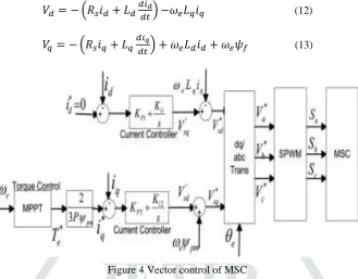
The 1st span of equations (12) and (13) shows that stator d-q axis currents maintained by regulating the direct and quadrature axis voltages, and the second part denotes the compensation terms. The block diagram of the control of machine side converter is shown in Fig. 4. The MPPT is applied to produce the reference generator power of electromagnetic torque based on generator speed. Below the speed of PMSG β is maintained to reference value zero and WT speed is moved in according to uneven wind speed like that the λ (TSR) is maximum. The base power is calculated from generator speed 𝜔𝑚.
The MPPT is applied from the 𝑃𝑡-𝜔𝑚 curve. Stator direct axis reference current is taken zero while stator q-axis reference current is estimated from base electromagnetic torque. The 𝑖∗
𝑑 and 𝑖∗𝑞 matched with measured 𝑖𝑑 and 𝑖𝑞 respectively which evaluate the error. Conventional PI controller is applied to overcome this error. Output of this PI controller is the expected direct and quadrature axis voltage 𝑉′
𝑑 and 𝑉′𝑞 respectively. After compensation, projected direct and quadrature axis base voltages 𝑉∗𝑑 and 𝑉∗𝑞 is transformed to abc frame and then SPWM applies switching to MSC. PI controllers has some problems like compensation terms required the generator parameters and rotor speed. plus, tough to balance the parameters and inadequate to handle the system nonlinearity.
V.CONVENTIONAL CONTROL OF GSC 5.1 GSC Modelling
The dc-link capacitor amongst machine side converter and load side converter, three-phase voltage source inverter work as the voltage at the PCC in the WPS shown in Fig. 1. The voltage stability through the grid filter is;
(
𝑉
∗ 𝐺𝑑
𝑉
∗𝐺𝑞
) = 𝑅
𝑓(
𝑖
𝐺𝑑𝑖
𝐺𝑞) + 𝐿
𝑓 𝑑 𝑑𝑡(
𝑖
𝐺𝑑𝑖
𝐺𝑞) + 𝜔
𝐺𝐿
𝑓(
−𝑖
𝐺𝑞𝑖
𝐺𝑑) + (
𝑉
𝑑𝑉
𝑞)
(14)Where 𝜔𝐺 is the grid frequency,𝑉𝑑, 𝑉𝑞, 𝑉∗𝐺𝑑 and 𝑉∗𝐺𝑞 are the VSI and PCC voltages, respectively, 𝑖𝐺𝑑 and 𝑖𝐺𝑞 are current components passing through VSI and grid, 𝐿𝑓 and 𝑅𝑓 are the inductance and resistance of filter[12][13].
In the PCC voltage frame. The rapid active and reactive powers on the load side are relative to the direct and quadrature axis current of the grid, and steady-state powers are relational to the direct and quadrature axis output voltages.
The instantaneous and steady-state powers equations are;
𝑝(𝑡) = 𝑉
𝑑𝑖
𝑑+ 𝑉
𝑞𝑖
𝑞= 𝑉
𝑑𝑖
𝑑 (15)𝑞(𝑡) = 𝑉
𝑞𝑖
𝑑− 𝑉
𝑑𝑖
𝑞= −𝑉
𝑑𝑖
𝑞 (16)𝑃 = 𝑉
𝑑𝑉
∗𝑞/𝑋
𝑓 (17)𝑄 = 𝑉
𝑑(𝑉
∗𝑑− 𝑉
𝑑)/ 𝑋
𝑓 (18)
5.2 GSC Control
© 2019 JETIR May 2019, Volume 6, Issue 5 www.jetir.org (ISSN-2349-5162)
𝑉
∗𝑑
= (𝑅
𝑓𝑖
𝑑+ 𝐿
𝑓 𝑑𝑖𝑑𝑑𝑡
) −𝜔
𝐺𝐿
𝑓𝑖
𝑞+ 𝑉
𝑑 (19)𝑉
∗𝑞= (𝑅
𝑓𝑖
𝑞+ 𝐿
𝑓 𝑑𝑖𝑞𝑑𝑡
) + 𝜔
𝐺𝐿
𝑓𝑖
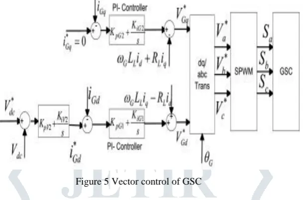
𝑑 (20)The first part of above eqn. (19) and (20) shows that stator direct and quadrature axis currents can be synchronized by regulating the d-axis and q-axis voltages, and the 2nd part of it denotes the compensation spans. The figure of the vector control of generator side controller is shown in Fig. 5.
Figure 5 Vector control of GSC
The load side converter is regulated based voltage based control to adjust the voltage at the dc-link and reactive power of the system. Grid quadrature axis base current set to be zero and direct axis base current is projected from the external loop of 𝑉𝑑𝑐. Reference 𝑉∗
𝑑𝑐 is compared with the found value of 𝑉𝑑𝑐 which produce the base 𝑖∗𝐺𝑑. projected base direct and quadrature axis currents 𝑖∗
𝐺𝑑 and 𝑖∗𝐺𝑞 compared with direct axis and quadrature axis currents 𝑖𝑑 and 𝑖𝑑 which are measured earlier L filter. Errors are input to PI controller which tweak the error. After compensation, projected direct and quadrature axis reference voltages 𝑉∗
𝐺𝑑 and 𝑉∗𝐺𝑞 is transformed to abc frame using rotor angle 𝜃𝐺 then SPWM generates the switching pulses of GSC.
5.3 DC-Link Voltage Control
For PMSG wind power system, the max. power fetched from wind has to be supplied to grid via dc-link capacitor and load side converter. The dc-link voltage control is key part for PMSG system as it is completely varying from DFIG system. Conventional control offers better performance and better dc-link voltage regulation. Thus, controlling of BTB converters can be decoupled by generator side controller for MPPT control and the load side controller for the voltage of the dc-link regulation so that power fetched from the wind can be moved to the grid with stable dc-link voltage.
5.4 Controlling Reactive Power
The load side converter works in reactive power control. In this scheme, quadrature axis base current is too originated from reactive power regulator. In the ac system voltage support control mode, quadrature axis base current is originated from voltage regulator on grid side. The load side converter creates the needed reactive power depending on how much voltage drop across the Filter and PCC. If the load side converter reaches to its physical restraints due to a maximum active power moved from the generator to the grid via load side converter, load side converter works in ideal state to control dc-link voltage in importance through necessity of reactive power to grid [18].
VI.DISCUSSIONS OF SIMULATION RESULTS
We have conducted various simulations the system in Matlab/Simulink with different values of parameters in order to examine stated control scheme. The PI controllers’ workability examined with various conditions. The WT and PMSG parameters in Table 1. we are controlling the dc-link voltage constantly at 340 V, the capacitance value at dc-link capacitor is about 1650 μF, and the switching frequency for the MSC and the GSC is 5 KHz, the grid side voltage is 220 V(rms)/50 Hz [18], [38].
6.1 Normal Grid Condition at Rated Speed
Table 1 Parameters of PMSG
Rated Power 2.68 [kW]
Voltage / Frequency 220 [V] / 60 [Hz]
Rated Flux 0.468 [Wb]
Rated Current 9.8 [A]
Torque Constant 1.72 [N.m/A]
Rated Speed 1200 [rpm]
Pole Pair 3
Moment of Inertia 0.00331 [Kg· m3]
Stator Resistance 0.49 [Ω]
Stator Inductance 5.35 [mH]
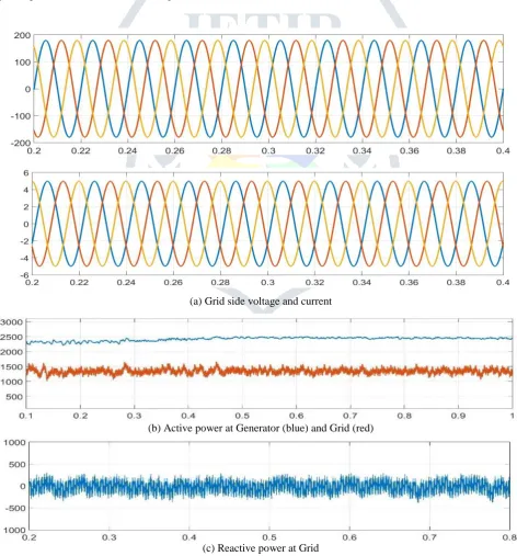
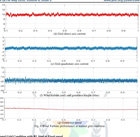
Fig. 6 shows the system operation at base wind speed of 15.5 m/s. Fig. 6 (a) displayed, grid voltage is 127 V (rms) and grid current is 6.96 A (rms). Generator power is 2.7 KW and grid power is 2.67 kW while reactive power on grid side is zero displayed in Fig.6. Grid direct axis current is 9.85 A, and quadrature axis current is zero, shown in Fig.6. Wind turbine and generator torques are 22 Nm and 22.4 Nm respectively, shown in Fig.6 and generator speed is 1200 rpm, shown in Fig.6. DC-link voltage is regulated at 340 V at rated wind speed.
(a) Grid side voltage and current
(b) Active power at Generator (blue) and Grid (red)
© 2019 JETIR May 2019, Volume 6, Issue 5 www.jetir.org (ISSN-2349-5162)
(d) Grid direct axis current
(e) Grid quadrature axis current
(f) Wind turbine (red) and generator torque (blue)
(g) Generator speed
Fig. 6 Wind Turbine performance at normal grid condition
6.2 Normal Grid Condition with RL load at Fixed speed
Fig. 7 shows the system operation at rated wind velocity of 15.5 m/s with active load of 1.2 kW and reactive load of 0.6 kVAr. Load voltage is 220V and load current is 4.81 A with p.f. of 0.9 lagging shown in Figure7(a).
Hence, the RL load connected next to the GSC and before the Grid. Thus, active & reactive powers are differing at load side converter and grid. Active power and reactive power flows subject to the load demand. Load side converter active power is about 2.67 kW and active power at grid side shows around 1.45 kW as the load of 1.2 kW is connected in between as shown in Fig. 7.
Due to the reactive power is controlled at GSC side for optimum active power transfer from generator to the grid and to acquire unity power factor control, required reactive power 0.5 kVAr to the load is from the grid in place of the load side converter, which shows in Fig. 7. Regulated dc-link voltage 340 V, Grid voltage of 127 V, and current of 4.2 A with unity power factor, Wind turbine and generator torque, generator speed and d-axis grid current are same as previous case.
(b) GSC (blue) and grid (red) active power
(c) GSC (blue) and grid (red) reactive power
(d)Voltage across dc-link Capacitor
(e) Inverter voltage and current with unity power factor
Fig. 7 Wind generation performance at normal grid condition with R-L load at rated wind speed 15.5 m/s.
6.3 RL load at Wind Speed 11.5 m/s
Fig. 8 shows the system performance at 11.5 m/s wind speed with 3.5 kW active and 1.5 kVAr reactive power load. Here, output of load side converter is 1.1 kW active power and the load needs 3 kW active and 1.5 kVAr reactive power. Fig. 8 shows, the 1.675 kW active and 1.5 kVAr reactive power is from the grid while 1 kW active and zero reactive power from load side converter.
© 2019 JETIR May 2019, Volume 6, Issue 5 www.jetir.org (ISSN-2349-5162)
(a) V and I at load with 0.89 lagging power factor
(b) Active power at GSC (blue) and grid (red)
(c) GSC (blue) and grid (red) reactive power
(d) GSC d-axis current
(e) Wind turbine (red) and generator torque (blue)
(f) Generator speed
(g) dc-link voltage
(h) Power coefficient (𝐶𝑝)
6.4 Constant Load and Varying Wind Speed
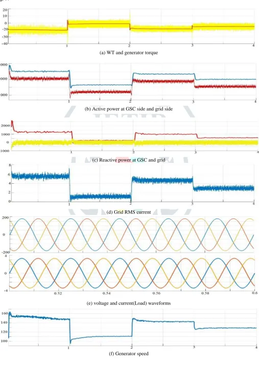
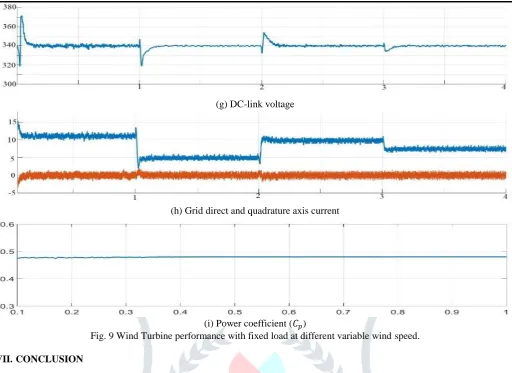
Fig. 9 shows the system operation at 17 m/s, 12 m/s, 15.5 m/s and 14 m/s of continuously changing wind speed with constant load 900 W. Wind turbine torque, generator torque, grid current, GSC active and reactive power, grid active and reactive power, load voltage, load current, generator speed, dc-link voltage, grid direct axis and quadrature axis current and Cp are shown from Fig. 9.
(a) WT and generator torque
(b) Active power at GSC side and grid side
(c) Reactive power at GSC and grid
(d) Grid RMS current
(e) voltage and current(Load) waveforms
© 2019 JETIR May 2019, Volume 6, Issue 5 www.jetir.org (ISSN-2349-5162)
(g) DC-link voltage
(h) Grid direct and quadrature axis current
(i) Power coefficient (𝐶𝑝)
Fig. 9 Wind Turbine performance with fixed load at different variable wind speed.
VII.CONCLUSION
This study has analyzed the conventional PI scheme of flexible speed DD-PMSG for grid assistance. This work shows how the control of generator side converter and load side converter modelled through the conventional voltage oriented control scheme and applied with the MPPT on machine side. Reactive power and dc-link voltage regulation on load side converter of a PMSG based wind power system.
Full work with various conditions verifies that the PMSG WPCS which is based on the conventional vector control method, can satisfy the PMSG WT system with better performance for fixed and flexible wind situations and also for varied load positions. The controller can optimize the output power of VSWT through various wind and load situations. The test outputs of the planned control strategy have proved outputs results for a 2.68 KW PMSG system with different load settings.
VIII.REFERENCES
[1] M. H. Qais, H. M. Hasnain, “Low voltage ride-through capability enhancement of grid-connected permanent-magnet
synchronous generator driven directly by variable speed wind turbine: a review” International Conference on Renewable Power Generation 2017.
[2] S K Gupta, R K Srivastava “LVRT Capability Evaluation of Variable-Flux PMSG based WECS”. IEEE Transportation
Electrification Conference, ITEC-India, 2017.
[3] Yunlu Guo, Hua Geng, Geng Yang, “LVRT Capability and Improved Control Scheme of PMSG-based WECS during
Asymmetrical Grid Faults” IEE Transections 2013
[4] Shrikant Mali, B. E. Kushare, “Fulfillment of Low Voltage Ride-Through Requirement of D-PMSG Based Wind Energy
Conversion System Using Generator-Rotor Inertia” IEEE 2015
[5] T. Ayodele, A. Jimoh, J. L. Munda “Challenges of Grid Integration of Wind Power on Power System Grid Integrity: A
Review” International Journal of Renewable Energy Research 2012.
[6] Hu Shuju, Xu honghua “Experimental Research on LVRT Capability of DFIG WECS during Grid Voltage Sags” IEEE
transaction.
[7] Shrikan Mali, B. E. Kushare “Fulfillment of Low Voltage Ride-Through Requirement of D-PMSG Based Wind Energy
Conversion System Using Generator-Rotor Inertia” IEEE Transactions 2015.
[8] Shrikant S Arma, Jaydeep s Lapu, Bhim Singh, “PMSG Based Grid Integrated Wind Energy Conversion System with
Controlled Power Injection” IEEE transection 2014.
[9] Chia-nan Wang, Khoa Sun Le, “Modelling of a PMSG Wind Turbine with Autonomous Control”, Mathematical Problems in Engineering · May 2014.
[10] Junfei Chen, Hongbin Wu, Ming Sun, Weinan Jiang, Liang Cai, and Caiyun Guo, “Modeling and Simulation of Directly
Driven Wind Turbine with Permanent-Magnet Synchronous Generator”, IEEE 2012.
[11] Rini Ann Jerin, Prabhakaran N, Thirumoorthy A. D., “A review on LVRT Capability in Wind Turbine of India and
Challanges in Implementation”
[12] Eung-Sang Kim, Byeong-Mun Song and Kwang Y. Lee, “Modeling and Analysis of a Grid-Connected Wind Energy Conversion System Using PSCAD/EMTDC”, IEEE 2010.
[13] Ming Yin, Gengyin Li, Ming Zhou, Chengyong Zhao, “Modeling of the Wind Turbine with a Permanentb Magnet
[14] A.G. Sanchez, M.G. Molina, A.M. Rizzato Lede, “Dynamic model of wind energy conversion systems with PMSG-based
variable-speed wind turbines for power system studies”, IJHE 2012.
[15] S. Benelghali, M.E.H. Benbouzid and J.F. Charpentier, “Comparison of PMSG and DFIG for Marine Current Turbine
Applications”, ICEM 2010.
[16] P Dey, Manoj Datta, Nuwantha Fernando, “Coordinated Control Technique of PMSG based Wind Energy Conversion
System during Repetitive Grid Fault”, IEEE 2018.
[17] N. S. Ting, Yusuf Yasa, Yakup Sahin, “Comparison of SVPWM, SPWM and HCC Control Techniques in Power Control of PMSG used in Wind Turbine Systems” IEEE 2015.S. Müller, M. Deicke, and R. W. De Doncker, “Doubly fed induction generator system for wind turbines,” IEEE Ind. Appl. Mag., vol. 8, no. 3, pp. 26-33, May 2002.
[18] Manish M Pandya, Deepa B. Karavat, “Reactive Power Control of Grid Integrated PMSG Wind Energy Generation”, Parul
University International Conference on Engineering & Technology (PiCET-2018): Smart Electrical, Feb. 2018.
[19] Comparison of direct-drive and geared generator concepts for wind turbines,” IEEE Trans. Energy Convers., vol. 3, no. 21, pp. 725–733, Sep. 2006.
[20] Iulian Munteanu, Antoneta Iulian, Bratcu Nicolaos, Antonio Cutululis, Emil Ceang, “Optimal control of wind energy
system,” Springer-Verlag London Limited, 2008.
[21] Gonzalo Abad, Jesus Lopez, Miguel A. Rodryguez, Luis Marroyo, Grzegorz Iwanski, “Doubly fed induction machine,
Modeling and control for wind energy generation,” Institute of Electrical and Electronics Engineers, Inc. 2011.
[22] J. Hui, A. Bakhshai, P.K. Jain, “An energy managemenr scheme with power plant capability and an adaptive maximum power point tracking for small standalone PMSG wind energy system,” IEEE Trans. Power Electron., 31(July (7) (2016) 4861-4875.
[23] Dao Zhou, Frede Blaabjerg, Toke Franke, Michael Tonnes, Mogens Lau, “Comparison of wind power converter reliability with low speed and medium speed PMSG,” IEEE Trans. Ind. Electron., 62 (October (10)) (2015) 6575-6584.
[24] A.M. De Broe, S. Drouilhet and V. Gevorgian, “A peak power tracker for small wind turbine in battery charging application,” IEEE Trans. Energy Convers., vol.14 no. 4, pp. 1630-1635, Dec. 1999.
[25] M. Chinchilla, S. Arnaltes, and J. C. Burgos, “Control of PMSG applied to variable-speed wind-energy systems connected to the grid,” IEEE Trans. Energy Convers., vol. 21 no. 1, pp. 130-135, Mar. 2006.
[26] W. Liu, L. Chen, J. Ou, and S. Cheng, “Simulation of PMSG wind-turbine system with sensorless control technology based
on model reference adaptive system,” in proc. Int. Conf. Elect. Mach. Syst. Beijing, China, 2011, pp. 1-3
[27] Singh, M., Khadkikar, V., “Grid synchronisation with harmonics and reactive power compensation capability of a permanent
magnet synchronous generator based variable speed wind energy conversion system,” IET Power Electron., 2011, 4, (1), pp. 122–130
[28] K. Bunjongjit, Y. Kumsuwan, “MATLAB/simulink modeling of stator current control of PMSG for grid-connected systems,”
Proc. Int. Elect. Enngg., congress 2014.
[29] J. Belhadj and X. Roboam, “Investigation of different methods to control a small variable-speed wind turbine with PMSM
drives,” J. Energy resources Technol., vol. 129, pp. 200–213, Sep. 2007.
[30] S. Li, T. A. Haskew, and Y. Hong, “PMSG maximum wind power extraction control using adaptive virtual lookup table
approach in direct-current vector control structure,” Int. J. Energy Res., vol. 35, no. 11, pp. 929–1022, Sep. 2011.
[31] S. Li, T. A. Haskew, and L. Xu, “Control of HVDC light systems using conventional and direct-current vector control
approaches,” IEEE Trans. Power Electron., vol. 25, no. 12, pp. 3106–3118, Dec. 2010.
[32] J. Matas, M. Castilla, J. M. Guerrero, L. Garcia de Vicuna, and J. Miret, “Feedback linearization of direct-drive synchronous
wind-turbines via a sliding mode approach,” IEEE Trans. Power Electron., vol. 23, no. 3, pp. 1093–1103, May 2008.
[33] S. Heier, Grid Integration of Wind Energy Conversion Systems, 2nd ed. New York: Wiley, 2006.
[34] A. Miller, E. Muljadi, and D. S. Zinger, “A variable speed wind turbine power control,” IEEE Trans. Energy Convers., vol. 12, no. 2, pp. 181–186, Jun. 1997.
[35] A. R. Bergen and V. Vittal, Power System Analysis, 2nd ed. Upper Saddle River, NJ: Prentice-Hall, 2000.
[36] J. Belhadj and X. Roboam, “Investigation of different methods to control a small variable-speed wind turbine with PMSM
drives,” J. Energy Resources Technol., vol. 129, pp. 200–213, Sep. 2007.
[37] G. Michalke, A.D. Hansen, T. Hartkopf, Control strategy of a variable speedwind turbine with multipole permanent magnet synchronous generator, in: Eur. Wind Energy Conf. Exhib., Milan, Italy, May 7–10, 2007.
[38] S. Li, T. A. Haskew, and L. Xu, “Conventional and novel control designs for direct driven PMSG wind turbines,” Electr. Power Syst. Res., vol. 80, no. 3, pp. 328–338, Mar. 2010.
[39] Y. Errami, and M. Ouassaid, “Modelling and control strategy of PMSG Based Variable Speed Wind Energy Conversion
System,” in Proc. ICMCS, 2011, pp. 1-6.
[40] H. Polinder, F. F. Avan der Pijl, and P. Tavner, “Comparison of direct-drive and geared generator concepts for wind turbines,” IEEE Trans. Energy Convers., vol. 21, no. 3, pp. 543–550, Sep. 2006.