A Study on Residual Compression Behavior of Structural Fiber
Reinforced Concrete Exposed to Moderate Temperature Using Digital
Image Correlation
G. Srikar, G. Anand, and S. Suriya Prakash*
(Received March 5, 2015, Accepted January 26, 2016, Published online February 19, 2016)
Abstract: Fire ranks high among the potential risks faced by most buildings and structures. A full understanding of temperature effects on fiber reinforced concrete is still lacking. This investigation focuses on the study of the residual compressive strength, stress strain behavior and surface cracking of structural polypropylene fiber-reinforced concrete subjected to temperatures up to 300C. A total of 48 cubes was cast with different fiber dosages and tested under compression after exposing to different temperatures. Concrete cubes with varying macro (structural) fiber dosages were exposed to different temperatures and tested to observe the stress–strain behavior. Digital image correlation, an advanced non-contacting method was used for measuring the strain. Trends in the relative residual strengths with respect to different fiber dosages indicate an improvement up to 15 % in the ultimate compressive strengths at all exposure temperatures. The stress–strain curves show an improvement in post peak behavior with increasing fiber dosage at all exposure temperatures considered in this study.
Keywords:structural polypropylene fibers, fiber dosage, digital image correlation (DIC), residual compressive strength, post-peak behavior.
1. Introduction
Fiber reinforced concrete (FRC) is a concrete mix con-taining water, cement, fine and coarse aggregates and dis-continuous fibers. The addition of fibers to concrete has been shown to enhance the toughness of concrete. There are many kinds of fibers, both metallic and polymeric, which have been used in concrete to improve specific engineering properties of the concrete. A concrete beam containing metallic/synthetic fibers suffers damage by gradual development of single or multiple cracks with increasing deflection, but retains some degree of structural integrity and post-crack resistance even under considerable deflection (Bentur and Mindess1990). A similar beam without fibers fails suddenly at a small deflec-tion by separating it into two pieces.
Synthetic fibers have attracted attention in the recent years for reinforcing cementitious materials. Polypropylene fibers belong to the category of synthetic fibers and are available in two different forms: (a) monofilaments and (b) fibrillated. Monofilament fibers are single strand of fibers having uni-form cross-sectional area. Fibrillated fibers are manufactured in the form of films or tapes that are slit in such a way that they have a net like physical structure. Polypropylene fibers
are also categorized as micro-synthetic or macro-synthetic (structural) fibers. Micro-synthetic fibers are typically 12 mm long and 18lm in diameter, whereas the macro ones are significantly larger with 40–50 mm lengths and 1.0–1.5 mm wide. Micro synthetic fibers are found to be effective in reducing crack formation at an early stage of the cast and in severe weather conditions (e.g. in dry climatic zones). In the recent years, the usage of macro synthetic (structural) fibers has significantly increased for reducing the usage of normal steel reinforcement.
Fire ranks high among the potential risks faced by most buildings and structures. Compressive strength of concrete decreases about a quarter of its room temperature strength within the range of 200–400C (Cheng et al. 2004). An assessment of the degree of deterioration of concrete after exposure to high temperatures can help engineers to decide whether it can be repaired or demolished. There is a need to fully understand the effects of elevated temperatures on con-crete. In fiber reinforced concrete (FRC), elevated temperature causes synthetic fibers to melt and thereby increasing the porosity in concrete. Increase in porosity result in the escape of vapor pressure and thereby lowers the risk of spalling when exposed to elevated temperatures. Moreover, influence of structural fiber reinforcement on residual properties of con-crete exposed to different temperatures is relatively not well understood. This paper aims to present the effects of moderate temperature exposure [up to 300C] on the compressive stress–strain behavior of concrete reinforced with structural polypropylene fibers. An experimental program was designed and carried out involving compressive load testing of 48
Department of Civil Engineering, Indian Institute of Technology, Hyderabad, India.
*Corresponding Author; E-mail: [email protected] CopyrightThe Author(s) 2016. This article is published with open access at Springerlink.com
International Journal of Concrete Structures and Materials Vol.10, No.1, pp.75–85, March 2016
concrete cubes with temperature exposure and fiber dosage as the test variables.
2. Literature Review
2.1 Behavior of FRC
Many kinds of fibers including metallic and polymeric is widely used in concrete for their advantages (Soroushian et al.1992; Song et al.2005; Alberti et al.2014). Previous research has shown that no single fiber-reinforced concrete has the perfect mechanical properties. There are several properties that a good reinforcing fiber must have which influence the mechanical behavior of fiber-reinforced con-crete like its tensile strength, ductility, high elastic modulus, elasticity, and Poisson’s ratio. Fibers must be much stronger than the concrete matrix in tension, since the load bearing area is much less than the matrix. The proportion of the load carried by the fiber depends directly upon the comparative elastic modulus of the fiber and concrete matrix. If the elastic modulus of the fibers is less than that of the concrete matrix, the fibers will contribute relatively little to the concrete behavior until after cracking.
Recently, many researchers have investigated the mechanical properties of the hybrid fiber-reinforced concrete (Mobasher and Li 1996; Alberti et al. 2014). Aslani and Nejadi (2013) explored the properties of self-compacting concrete (SCC) with fiber reinforcement. They developed a test program to understand the mechanical properties including compressive and splitting tensile strengths, moduli of elasticity and rupture, compressive stress–strain curve and energy dissipation under compression. They investigated four different SCC mixes including (i) plain SCC, (ii) steel, (iii) polypropylene and (iv) hybrid fiber reinforced SCC. Experimental investigation and analytical study were per-formed to develop a simple and rational mathematical model for the prediction of the mechanical properties which were found to be quite comparable with the test data.
2.2 Behavior of FRC Under Compression and Flexure
Compressive tests showed that the fibers in concrete had only a marginal effect on the compressive strength of con-crete (Olivito and Zuccarello 2010; Soulioti et al. 2011). However, studies on compression behavior of synthetic fiber reinforced concrete is very limited. Contradictory test results have been reported by different investigators regarding the effects of polypropylene fibers (micro fibers) on the com-pressive and flexural strengths of concrete. Differences in results may have been caused by the differences in matrix composition, polypropylene fiber type and volume fraction, and manufacturing conditions. Hughes and Fattuhi (1976) reported that compressive strength decreases, but flexural properties are improved with increasing synthetic fiber content. This is practical because a considerable part of the matrix is replaced with a weaker material. In addition, insufficient compaction due to reduced slump may be the reason for the decline in strength values (Soroushian et al.
1992). Ahmed and Imran (2006) reported that the com-pressive strength and tensile strength of concrete reinforced with polypropylene fibers are not significantly affected, if the fiber inclusion is limited to very low volume percentages. However, at higher fiber dosages, the compressive strength was found to be adversely affected.
Few studies in the past have reported that strength increases with respect to synthetic fiber dosage (Mindess and Vondran 1988; Song et al. 2005; Alberti et al.2014). The authors have observed that the improvements in compressive strength came principally from the fibers interacting with the advancing cracks. At increased compression loads, the fibrous concrete cylinders develops lateral tension due to Poisson’s effect, thus initiating cracks and advancing those cracks. The debonding at the fiber–matrix interface happens due to the tensile stresses perpendicular to the expected path of the advancing crack. As the advancing crack finally reaches the interface, the tip of the crack encountered a process of blunting because of the already present debonding crack. The blunting process reduces the crack-tip stress concentration, thus blocking the forward propagation of the crack and even diverting the path of the crack. The blunting, blocking, and even diverting of the crack allows the fibrous concrete cylinders to withstand additional compressive load and thereby increasing its compressive strength over the nonfibrous control concrete.
Mechanical properties including compressive and tensile strength of fiber-reinforced (both steel and synthetic) con-crete have been relatively studied well in the last decades (Barros and Figueiras 1999; Olivito and Zuccarello 2010; Soulioti et al.2011). Li (2002) found that the polypropylene fibers only marginally increased flexural tensile strength. However, after cracking, the fibers were found to greatly increase the ultimate strain, though the load carrying capacity is decreased. However, the fracture mechanisms and fracture energy of synthetic fiber-reinforced concrete is still a matter of interest. It is in fracture processes where the fibers absorb energy and provide ductility and toughness to the FRC. It is worth mentioning that most of the previous studies focused on fibrillated or micro fibers and not on structural/macro synthetic fibers used in this study. More-over, the information on temperature effects on structural fiber reinforced concrete is very scarce and this study attempts to improve the understanding in this area.
2.3 Temperature Effects on Concrete With and Without Fibers
changes lead to the decrement of the stiffness of concrete and increment in an irrecoverable deformation. Various investi-gations validate that depletion of strength and stiffness of concrete with increasing temperature, exposure time and thermal cycles (Poon 2004; Cheng et al. 2004; Noumowe 2005). It is observed that at approximately 100C, weight loss indicates water evaporation from micro pores. The dehydra-tion of ettringite (3CaOAl2O33CaSO4, 32H2O) occurs between 50 and 110C. At 200C, there is further dehydra-tion, which causes light weight loss. The weight lost at various moisture contents has been observed to be different until the local pore water and the chemically bound water are gone. Further weight loss is not perceptible at approximately 250–300C.
Poon (2004) investigated the effects of elevated tempera-tures on the compressive strength stress–strain relationship (stiffness) and energy absorption capacities (toughness) of high strength concretes with different mineral admixtures like metakaolin (MK), silica fume (SF), Fiber type (steel or Polypropylene) and fiber dosage. The authors reported that after exposure to 600–800C, there was 23–45 % retaining of compressive strength depending on the fiber dosage. However, they reported that losses in stiffness were much quicker than compressive strength and energy absorption. Poly-propylene (PP) fibers reduced energy absorption capacity of the concretes compared to steel fibers. Cheng et al. (2004) reported that compressive strength decreases about a quarter of its room temperature strength within the range of 100–400C whereas the actual depletion of strength was observed at higher temperature for fiber rein-forced ones. Noumowe (2005) studied the temperature ran-ges of the decomposition reactions using thermo-gravimetric analysis and differential scanning calorimetric analysis. They also reported that scanning electron microscopy results val-idated the increase in porosity with poly-propylene fiber reinforcement at high temperatures which may result in lowering of vapor pressure hence lowering the risk of spalling when exposed to elevated temperatures.
The fibers can also improve the residual properties of concrete after exposure to elevated temperatures which qualitatively indicates the degree of deterioration caused. An assessment of the degree of deterioration of concrete struc-ture after exposure to high temperastruc-tures can help engineers to decide whether a structure can be repaired rather than required to be demolished (Xiao and Falkner 2006). Hor-iguchi (2005) experimentally proved that the addition of polymeric or steel fibers alters the residual compressive strength of concrete. Specimens were heated at a rate of 10C/min up to 200 or 400C and held for 1 h at high temperature; they were then tested at room temperature. The author concluded that hybrid fibers (polypropylene and steel fibers) improve the residual compressive strength of high-strength concrete exposed to a temperature up to 400C. Orteu et al. (2007) used DIC for assessing the 3D orientation of the fibres on ruptured ceramic refractories to correlate the micro-mechanical model of fibre pullout with macro behavior under tension. Pain and Lamon (2005) used DIC for determining elastic moduli and Poisson coefficient of
thin silicon based joints. It is worth mentioning that full-field measurements have not been applied yet for understanding the residual stress strain behavior of synthetic fiber rein-forced concrete under compression and is the focus of this paper.
3. Research Significance
The literature review indicates that many studies in the past have investigated the behavior of concrete at high temperatures. There are only limited data on high tempera-ture properties PPFRC under compression in particular the stress–strain behavior. Moreover, there is considerable variations and discrepancies in the high temperature behavior of synthetic fiber reinforced concrete. It is worth mentioning that most of the previous studies focused on fibrillated or micro fibers and not on structural synthetic fibers used in this study. Therefore, the present study tries to contribute to valuable information on stress–strain behavior of structural fiber reinforced concrete under compression exposed to moderate temperature.
4. Experimental Program
4.1 Materials
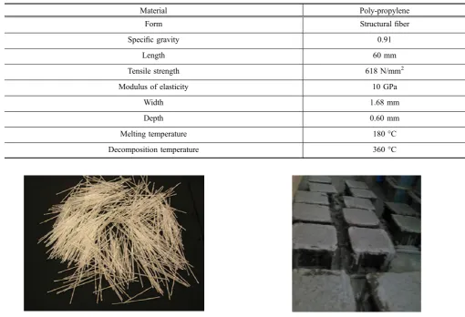
The cementitious materials used in this study are ordinary portland cement (OPC) grade 53, and fly ash. Crushed granite was used as coarse aggregate with nominal sizes of 12.5 and 20 mm. The specific gravity of the coarse aggregate was 2.63 in concrete mixtures, the 12.5 and 20 mm coarse aggregates were used in the proportion of 2:3. Natural river sand, of specific gravity 2.62 was used as fine aggregate. Structural polypropylene (PP) fibers with a length, width and thickness of 60, 1.68 and 0.60 mm respectively was used (Table1). Figure1shows the picture of structural PP fibers used in this study. This monofilament structural polypropylene fiber is commercially known as FibreTuffTM. The fibers are made of a modified polyolefin and have a modulus of elasticity of about 10 GPa and tensile strength between 550 and 640 MPa. The fibers are continually embossed surface anchorage mechanism to enhance bonding.
4.2 Mix Proportioning
contained no fiber. A detailed overview of the mix propor-tions in kg/m3is as follows: Water: 192; OPC: 298 Fly-ash: 127; River sand: 689; Fine aggregate (10 mm): 519; Coarse aggregate (20 mm): 519.
4.3 Specimen Preparation
The concrete mixes were prepared in a tilting drum type mixer. Both coarse and fine aggregate was weighed and placed into the concrete mixer moistened in advance and mixed for 3 min with the addition of saturation water. Thereafter, water was added with the addition of cement (together with fly ash) and mixed thoroughly for 3 min. Fibers were added finally and mixed for another 3 mins. For each mix, a total of 12 specimens comprising of cubes of 100 (length)9100 (breadth) 9100 mm (height) were cast in steel molds. Three samples for each fiber dosages of 0, 4, 5 and 6 kg/m3were tested after exposing at room tempera-ture (27C), 150, 200 and 300C respectively. The speci-mens, after removal from the steel molds at 1 day, were cured in water at 27C until the age of 28 days. Figure2 shows an image taken while casting the specimens.
4.4 Test Procedure
The cubes were tested under compression in this study. IS 456 2000 (2000) is typically used as standards for testing of cubes under compression. However, IS 456 (2000) does not have information related to displacement controlled testing
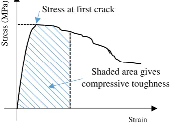
and therefore ASTM C39 (2004) was used as a reference for loading protocol. Cube specimens were tested in uni-axial compression using rigid steel plates on a servo-con-trolled compression testing machine using displacement control (Fig.3). After 28 days of curing, the fully saturated specimens were taken out and dried to saturated and surface dry status. Three specimens from each of the four mixes were grouped together and made into a batch. Each batch was heated in an electric oven to peak temperatures of 150, 200 and 300C at a definite temperature gradient of 2C/ min and the peak temperature was maintained for 1 h approximately. The diagrammatic representation of the temperature load is shown in Fig.4. The heated specimens were then cooled to room temperature and made ready for the compression testing. The specimens were then coated with a white paint as a primer on which a speckle pattern is created in order to obtain the strain values based on DIC technique. Displacement and load were measured through an external data acquisition system (DAQ). DIC measure-ments were used to calculate the strain corresponding to applied load (Fig.3a). The effectiveness of fiber rein-forcement is measured in terms of its energy dissipation capacity. It is also called as toughness index. Compressive toughness index (CTI) is defined as area under the stress– strain curves under compression, which is the energy absorbed prior to complete failure of specimen as shown in Fig.5.
Table 1 Specifications for structural polypropylene fibers.
Material Poly-propylene
Form Structural fiber
Specific gravity 0.91
Length 60 mm
Tensile strength 618 N/mm2 Modulus of elasticity 10 GPa
Width 1.68 mm
Depth 0.60 mm
Melting temperature 180C Decomposition temperature 360C
4.5 Digital Image Correlation
The digital image correlation (DIC) is an optical-numerical full-field surface displacement measurement method. It is based on a comparison between two images of the specimen coated by a random speckle pattern in the undeformed and in the deformed state (Sutton et al. 2009). Its special merits encompass non-contact measurement, simple optical setup, no special preparation of specimens and no special illumi-nation. The basic principle of the DIC method is to search for the maximum correlation between small zones (sub
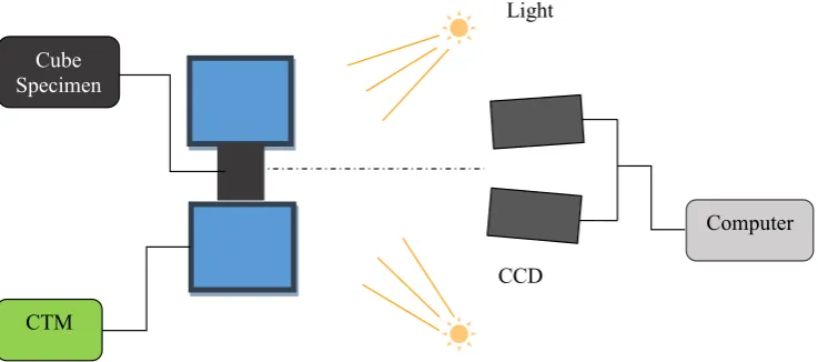
windows) of the specimen in the undeformed and deformed states, as illustrated in Fig.6. From a given image-matching rule, the displacement field at different positions in the analysis region can be computed. The simplest image-matching procedure is the cross-correlation, which provides the in-plane displacement fields u xð ;yÞ and v xð ;yÞ by matching different zones of the two images (See Eq. (1)). Experimental setup of a 3D DIC system is shown in Fig.7.
C uð ;vÞ ¼
Pm i¼1
Pm j¼1 f xi;yj
f
g x0
i;y0j
g
h i
ffiffiffiffiffiffiffiffiffiffiffiffiffiffiffiffiffiffiffiffiffiffiffiffiffiffiffiffiffiffiffiffiffiffiffiffiffiffiffiffiffiffiffiffiffiffiffiffiffiffiffi Pm
i¼1 Pm
j¼1f xi;yj
f
2
q ffiffiffiffiffiffiffiffiffiffiffiffiffiffiffiffiffiffiffiffiffiffiffiffiffiffiffiffiffiffiffiffiffiffiffiffiffiffiffiffiffiffiffiffiffiffiffiffiffiffiffiffiffiffiP m
j¼1 Pm
j¼1 g x0i;y0j
g
h i2
r
ð1Þ
whereC(u,v) is correlation coefficient which is function of translations ‘u’ and ‘v’. The coordinates or grid points (xi, yj) and (xi0,yj0)are related by the translations that occur between the two images. If the deformation is small and perpendicular to the optical axis of the camera, then the relation between (xiy) and (x0, y0) can be approximated by a 2D transformation given in Eqs. (2) and (3).
x0¼xþu0þ ou oxdxþ
ou
oydy ð2Þ
y0¼yþv0þ ov oxdxþ
ov
oydy ð3Þ
Here, u0and v0are translations of the center of the sub-image in the X and Y directions, respectively. The distances from the center of the sub-image to the point (x, y) are denoted bydxanddy. Thus, the correlation coefficientC(u,v) is a function of displacement components (u, v) and displacement gradients. In Eq.1, f(x, y) is the pixel intensity or the gray scale value at a point (x, y) in the original image andg(x, y) is the gray scale value at a point (x,y) in the translated imagef andgare mean values of the intensity matricesf andg, respectively.
Optical full-field measurement techniques such as reflec-tion photo elasticity, Moire´ interferometry, holographic and speckle interferometry, grid method and DIC are found very promising for the experimental stress/strain analysis of
a
b
1
4
Fig. 3 Test setup for compression testing of cubes.aDIC setup for strain measurement.bCompression testing machine.1. CTM machine.2. Controller.3. Camera.4. Light source. 5. DIC software.
Fig. 4 Temperature loading gradient.
Stress (MPa)
Strain Stress at first crack
Shaded area gives compressive toughness
materials and structures (Rastogi2000; Surrel2004; Gre´diac 2004; Robert et al.2007). All the interferometric techniques require stringent system stability and are very sensitive to vibration. However, DIC technique is easy to use, involves simple optics, less sensitive to vibration, no heavy surface preparation, reliable and it can be applied on any class of material. Moreover, it is truly a whole field noncontact measurement method. For above reasons, DIC is now becoming more popular and most widely employed for surface displacement and strain measurement in experi-mental mechanics.
Although the interferometric metrologies for deformation measurements are able to provide high-sensitivity and real-time representation of the deformation field through live fringes, they do have some inherent limitations. In particular, they are very sensitive to vibration and in situ measurement could always pose a problem. Also, the measurement results are often presented in the form of fringe patterns, therefore additional fringe and phase analysis techniques are required to recover the desired physical quantities from the fringe pat-terns. Since the recording process is generally nonlinear, resulting in difficulties in extracting partial fringe positions with high accuracy. But in the case of DIC one needs only two images: first one is reference and later acquired at deformed state relatively. Using these two images applying the corre-lation or doing pattern matching straight away one can get displacement field. It is an added advantage while doing these kind of in situ measurements especially during continuous loading. One has to do numerical differentiation of the
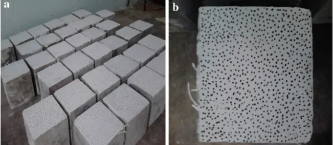
displacement field to get the strain field and it involves many intermediate steps. When a specimen is loaded its surface image deforms accordingly. Two different images represent different loading stages, one is the initial reference image and another is the deformed image. Calculating the transformation parameters for images under different loading conditions, both the displacement vector and deformation for each facet can be determined. In order to make the specimens reveal unique image patterns to apply correlation matching, usually black paint is lightly sprayed on white painted surfaces of the specimens. Figure8a, b shows all the pre-processed test specimens and typical speckle pattern respectively.
A Servo controlled hydraulic compression testing machine was used in this study. Testing was done in a displacement controlled mode at a slow rate of 0.01 mm/s. Artificial random speckle pattern over the specimen surface is gener-ated manually. The experimental setup comprises of a DIC system from Correlations Solutions, Inc. It consists of a grasshopper CCD camera (Point Crey-Grass-5055M-C) having a spatial resolution of 244892048 pixel. Two LED light sources are used to get an adequate image contrast. The camera was mounted on a tripod in front of the specimen (Fig.3) and was connected to a laptop for image acquisition. Ten images per second are grabbed using VIC Snap software from Correlated Solutions Inc. Post-processing of captured images was carried out using VIC-2D software from Cor-related Solutions Inc. Both the image acquisition and load cell output are synchronized using a National Instrument (NI) data acquisition card (DAC).
Fig. 6 Schematic diagram of the deformation relation.aUndeformed state,bdeformed state.
CTM
Cube Specimen
Light
Computer
CCD
The specimens were coated with a random speckle pattern to monitor the in plane surface strains. The load and the displacement data were recorded throughout the testing. The load on the specimens was continuously increased until it dropped to 30 % of the peak load. The error in DIC mea-surement could arise due to many sources such as illumi-nation variations, quality of the acquisition system, camera lens distortion, image noise, or it could be due to the error associated with the implementation of correlation algorithm like subset size, step size, strain window size, sub-pixel optimization algorithm, and sub-pixel intensity interpolation scheme. However, there are several parameters like subset size, step size and strain window size, which can influence the accuracy of measurements. The effect of some of these parameters has been investigated by carrying out a sensi-tivity analysis. The resolution of region of interest (ROI) is kept at 1199224 pixels corresponding to 10.5 mm 9 19.5 mm on physical scale. The spatial resolution is 11.35 pixel/mm. The average speckle size is 2.8 pixels. A subset size of 37937 pixels along with a step size of 7 pixels is chosen for performing the DIC post-processing. Once the strain computation is completed, the average value of each strain component from every strain map corre-sponding to each image grabbed during the test is extracted to generate the complete stress–strain curve.
5. Results and Discussion
5.1 Residual Compressive Stress–Strain
Behaviour
Compressive tests on each mix was carried out between 50 and 55 days from the day of casting. The obtained results are presented in Table2. The strain values are obtained from the DIC and the loading values are obtained from the load cell values of the compression testing machine. Vic-2D software was used to correlate the strain measurements. Fiber inclu-sions of all types increased the compressive strength only marginally. Higher compressive strength was obtained for a specimen with higher fiber dosage (6 kg/m3), whereas the lowest value was obtained in control specimen. Previous studies by authors (Rasheed and Prakash2015) on cellular lightweight concrete have indicated that the fiber dosage of
about 4–5 kg/m3is the optimum dosage beyond which there is not much strength increase. However, with an increase in temperature there is a decrease in the peak compressive strength. Decay in strength was not significant for specimens subjected to 150C. This indicated that fibers were not affected as they did not reach their glass transition temper-ature of 160C. At higher temperature (300C), strength decay was observed, indicating that there was no contribu-tion from fibers. Slight color change from grey to pale white has occurred to the specimens subjected to 200 and 300C indicating the initiation of chemical reactions with in the concrete matrix. However, the change in chemical reactions cannot be captured as there was no thermocouple in the center of the concrete samples. However, the interior of the sample is expected to experience a lower temperature and a part of the fibers could still be intact and could contribute to the residual strength.
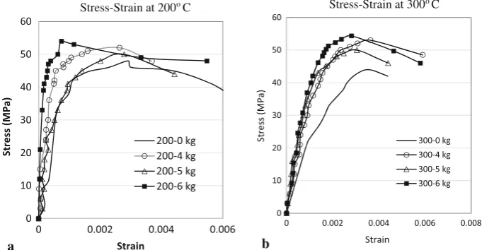
Stress–strain plots of compressive load testing of the specimens exposed to different temperatures are shown in Figs.9 and 10. Out of three samples tested, test result of sample which replicated the average behavior is used for comparison of behavior with respect to different temperature and fiber dosages. It is worth mentioning that small levels of inconsistency in the stress–strain behavior between samples was observed and could be due to smaller size (100 mm) of the cubes considered in this study. Due to smaller size of specimen, displacement transducers were not used and only DIC results were used for calculating the strains. Figures9 and 10 shows the pattern of the stress–strain curves for different temperature exposures. It is observed that with an increase in the fiber dosage, there is a slight increase in the compressive strength at room temperature conditions (Fig.9a). The improvements in strength is mainly due to the interaction of fibers with the advancing internal cracks under compression.
Concrete develops lateral tension at higher compressive loading due to Poisson’s effect, thus initiating cracks at micro levels. These cracks keep growing with increase in applied load. As the advancing crack approaches the fiber, the debonding at the fiber–matrix interface occurs due to the tensile stresses perpendicular to the expected path of the advancing crack. The blunting process reduces the crack-tip stress concentration, thus blocking the forward propagation
of the crack and even diverting the path of the crack. The blunting, blocking, and even diverting of the crack allows the fiber reinforced concrete to withstand additional com-pressive load, thus upgrading its comcom-pressive strength over the control specimen with no fibers.
Compressive strength of structural fiber reinforced speci-men were higher for concrete cubes tested at high
temperature (Fig.10). With an increase in fiber dosage, there is a slight improvement in the initial stiffness and post peak stiffness at all temperatures (Figs.9 and 10). This may be attributed to the pseudo autoclaving that is happening during the test procedure. Addition of fibers helps to reduce post-peak degradation in stiffness with increase in the fiber dosage. After heating, below 300C, the fibers have an
Table 2 Average peak compressive strength and compressive toughness index (CTI).
Fiber dosage (kg/m3) Property Room temperature 150C 200C 300C 0 Strength (MPa) 55.2 (0.7) 54.2 (1.2) 48.6 (2.4) 42.3 (1.4)
CTI (910-3) 5.3 (0. 08) 4.3 (0. 05) 4.1 (0. 1) 4.3 (0. 05) 4 Strength (MPa) 55.7 (1.8) 53.3 (1.6) 52.4 (0.7) 48.7 (2.1)
CTI (910-3
) 10.3 (0. 06) 8.4 (0. 05) 7.6 (0. 04) 6.8 (0. 04) 5 Strength (MPa) 56.8 (1.4) 55.1 (1.8) 54.3 (1.2) 50.4 (2.3)
CTI (910-3) 14.2 (0. 03) 10.2 (0. 09) 9.4 (0. 07) 8.7 (0. 06) 6 Strength (MPa) 57.5 (0.9) 56.2 (2.2) 55.4 (2.1) 51.3 (3.1)
CTI(910-3) 18.3 (0. 02) 14.2 (0. 06) 11.8 (0. 08) 9.4 (0. 09) The values in the parenthesis indicate standard deviation.
0 10 20 30 40 50 60
0 0.002 0.004 0.006
Stress (MPa)
Strain Stress-Strain at Room
Temperature
0- 0kg 0- 4kg 0- 5kg 0- 6kg
0 10 20 30 40 50 60
0 0.002 0.004 0.006
Stress ( MPa)
Strain
Stress-Strain at 150oC
150-0 kg 150-4 kg 150-5 kg 150-6 kg
Fig. 9 aStress versus strain at room temperature for different fiber dosages.bStress versus strain at 150C for different fiber dosages.
a b
0 10 20 30 40 50 60
Stress (MPa)
Strain
Stress-Strain at 200oC
200-0 kg 200-4 kg 200-5 kg 200-6 kg
0 10 20 30 40 50 60
0 0.002 0.004 0.006 0 0.002 0.004 0.006 0.008
Stress (MPa)
Strain
Stress-Strain at 300oC
300-0 kg 300-4 kg 300-5 kg 300-6 kg
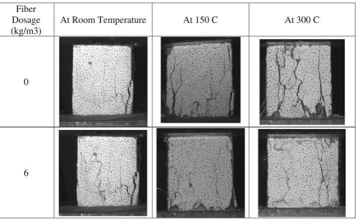
uncracking effect by allowing the dissipation of fluid over-pressure in the matrix. The fiber samples have greater stiff-ness compared to that of the non-fibred ones with an increasing gap until a temperature of 300C. Up to 300C considered in the study, macro-polypropylene reinforced cubes gives a pseudo-ductile behavior with an improved strength, stiffness and toughness than specimen without fibers. Thus, the safety of concrete structures submitted to temperature is increased. By melting at about 200C the polypropylene fibers are considered to create a porosity which allows a limitation of the pressure due to the evapo-ration of water treatment and thus a limitation of cracking. Therefore, the spalling of concrete was not observed for all specimens considered in this study. Moreover, the fiber decomposition temperature was about 360C and the fibers were effective in restraining the cracking with reduced efficiency until temperature of 300C. The typical failure modes of cubes with different fiber dosages at room tem-perature and at 300C is shown in Fig.11. Fiber reinforced specimen exhibited more distributed cracking at room tem-perature as well as at 300C.
The effect of fiber dosages at different temperatures on failure mode is shown in Fig.12. The effect of temperature exposure is shown in Fig.12a for specimen with no fibers and in Fig.12b for specimen with high fiber dosage of 6 kg/ m3. Figure12a shows that both the strength and stiffness is reduced for specimen exposed to a temperature of 300C. Moreover, the strain corresponding to peak stress also increased indicating the loss of stiffness. It can be inferred that the addition of high fiber dosage (6 kg/m3) helped to recover the stiffness lost at all temperature exposures (Fig.12b) when compared to specimen with no fibers. Residual strength increased due to addition of fibers at all temperatures.
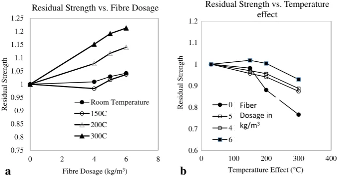
Variation of residual strength after temperature exposure with respect to fiber dosage is presented in Fig.13a. The efficiency of fibers in restoring the strength loss is higher at
higher temperature. Almost 25 % strength was restored by 6 kg/m3fiber dosage for at temperature exposure of 300C. Variation of residual strength with respect to temperature for different fiber dosage is explained in Fig.13b. Higher dosage of fibers is found to restore the strength and stiffness loss at all temperature exposure though the beneficial effect is more pronounced at higher temperature exposure. Due to time and resource constraints, the current research was confined to compressive stress–strain behavior on cube specimens exposed to moderate temperature levels up to 300C. Future research shall focus on the influence of fiber reinforcement on flexural strength, tensile strength, fresh concrete rheology and shrinkage cracking and residual properties which are more representative of fire-accidents. Idea of hybrid reinforcements with carbon and steel fibers at various dosages can also be explored.
6. Conclusions
Structural polypropylene fibers evaluated in the test pro-gram shows a good potential for improving the post-peak residual strength and toughness for temperature exposures up to 300C. Though the fibers started melting about 200C, it partially helped in reducing the drop of load resistance soon-after cracking and contributed to improving the post peak behavior at all temperature exposures. The cross sections of the failed specimen was examined and even distribution of fibers across the cross section was noted. Based on the limited test results, the following conclusions can be derived:
• There is a marginal increase in the compressive strength at room temperature with an increase in the fiber dosage. However, this increase in strength reduced at higher fiber dosages. The trend holds up even at high temperatures exposure up to 300 C.
Fiber Dosage (kg/m3)
At Room Temperature At 150 C At 300 C
0
6
• Compressive strength reduced up to 22 and 13 % for temperature exposure of 300 and 200C respectively. There is no strength decrease for a temperature exposure of 150C. Stiffness reduced more than strength at temperatures higher than 200C.
• The compressive strength and stiffness was recovered with increase in fiber dosage at all temperature expo-sures. Moreover, addition of macro fibers is found to reduce post-peak degradation in stiffness with increase in the fiber dosage.
• Compressive toughness was calculated as ratio of area under stress–strain curve of concrete to compressive strength. Compressive toughness increased significantly with respect to fiber dosage both at room temperature and at higher temperatures.
• DIC technology was successfully employed to strain measurement for concrete exposed to moderate temper-atures. Stress–strain curves were established from the strain measurements for all the tested specimen. DIC can
be used to study the damage mechanisms of concrete under compression with and without fiber reinforcement.
Open Access
This article is distributed under the terms of the Creative Commons Attribution 4.0 International License (http://creativecommons.org/licenses/by/4.0/), which per-mits unrestricted use, distribution, and reproduction in any medium, provided you give appropriate credit to the original author(s) and the source, provide a link to the Creative Commons license, and indicate if changes were made.
References
Ahmed, S., & Imran, A. (2006). A study on properties of polypropylene fiber reinforced concrete. In:Proceedings of
a
b
0 10 20 30 40 50 60
0 0.005 0.01 0.015
Stress (MPa)
Strain 0 Kg/m3
0- 0kg 150-0 kg 200-0 kg 300-0 kg
0 10 20 30 40 50 60
0 0.004 0.008
Stress (MPa)
Strain 6 kg/m3
0- 6kg 150-6 kg 200-6 kg 300-6 kg
Fig. 12 aStress versus strain with no fibers for different temperature exposure. b Stress versus strain with 6 kg/m3fibers for different temperature exposure.
0.75 0.8 0.85 0.9 0.95 1 1.05 1.1 1.15 1.2 1.25
0 2 4 6 8
Residual Strength
Fibre Dosage (kg/m3)
Residual Strength vs. Fibre Dosage
Room Temperature
150C
200C
300C
0.6 0.7 0.8 0.9 1 1.1 1.2
0 100 200 300 400
Residual Strength
Temperatture Effect (°C)
Residual Strength vs. Temperature effect
0 kg/m3
5 kg/m3
4 kg/m3
6 kg/m3 Fiber Dosage in kg/m3
a b
the 31st conference on Our World in Concrete & Struc-tures, Singapore.
Alberti, M. G., Enfedaque, A., & Ga´lvez, J. C. (2014). On the mechanical properties and fracture behavior of polyolefin fiber-reinforced self-compacting concrete. Construction and Building Materials, 55, 274–288.
Aslani, F., & Nejadi, S. (2013). Self-compacting concrete incorporating steel and polypropylene fibers: Compressive and tensile strengths, moduli of elasticity and rupture, compressive stress–strain curve, and energy dissipated under compression. Composites Part B Engineering, 53, 121–133.
ASTM C 39/C39 M-04. (2004). Standard test method for compressive strength of cylindrical concrete specimens. West Conshohocken, PA: Annual Book ASTM Standards. Barros, J. A., & Figueiras, J. A. (1999). Flexural behavior of SFRC: Testing and modeling.Journal of Materials in Civil Engineering, 11(4), 331–339.
Bentur, A., & Mindess, S. (1990).Fiber reinforced cementitious composites. London, UK: Elsevier.
Cheng, F. P., Kodur, V. K. R., & Wang, T. C. (2004). Stress-strain curves for high strength concrete at elevated tem-peratures.Journal of Materials in Civil Engineering, 16(1), 84–90.
Gre´diac, M. (2004). The use of full-field measurement methods in composite material characterization: interest and limita-tions.Composites Part A, 2004(35), 751–761.
Horiguchi, T. (2005). Combination of synthetic and steel fibres reinforcement for fire resistance of high strength concrete. In: MichaelP (Ed.) Proceedings of Central European Congress on Concrete Engineering, 8–9 September 2005, Graz, pp. 59–64.
Hughes, B. P., & Fattuhi, N. I. (1976). Improving the toughness of high strength cement paste with fiber reinforcement. Composite, 7(4), 185–188.
IS 10262. (2009).Concrete mix-properotioning guidelines. New Delhi: Buerau of Indian Standards.
IS: 456. (2000).Plain and reinforced concrete-code of practice (fourth revision). New Delhi, India: Bureau of Indian Standards.
Li, V. (2002). Large volume, high-performance applications of fibers in civil engineering. Journal of Applied Polymer Science, 83, 660–686.
Mindess, S., & Vondran, G. (1988). Properties of concrete reinforced with fibrillated polypropylene fibres under impact loading. Cement and Concrete Research, 18(1), 109–115.
Mobasher, B., & Li, C. Y. (1996). Mechanical properties of hybrid cement-based composites. ACI Materials Journal, 93(3), 284–293.
Noumowe, A. (2005). Mechanical properties and microstructure of high strength concrete containing polypropylene fibres
exposed to temperatures up to 200C.Cement and Con-crete Research, 35(11), 2192–2198.
Olivito, R. S., & Zuccarello, F. A. (2010). An experimental study on the tensile strength of steel fiber reinforced con-crete.Composites Part B Engineering, 41(3), 246–255. Orteu, J.-J., Cutard, T., Garcia, D., Cailleux, E., & Robert, L.
(2007). Application of stereovision to the mechanical characterisation of ceramic refractories reinforced with metallic fibres.Strain, 43(2), 1–13.
Poon, C. (2004). Performance concrete subjected to elevated temperatures. Cement and Concrete Research, 34(12), 2215–2222.
Puyo-Pain, M., & Lamon, J. (2005). Determination of elastic moduli and Poisson coefficient of thin silicon-based joint using digital image correlation. Proceedings of the 29th International Conference on advanced Ceramics and Composites, 2005, Cocoa Beach, FL.
Rasheed, M. A., & Prakash, S. S. (2015). Mechanical behavior of hybrid fiber reinforced cellular light weight concrete for structural applications of masonry. Journal of Building Materials and Construction, Elsevier, 98, 631–640. doi: 10.1016/j.conbuildmat.2015.08.137.
Rastogi, K. P. (2000).Photomechanics, topics in applied phy-sics. New York, NY: Springer.2000.
Robert, L., Nazaret, F., Cutard, T., & Orteu, J. J. (2007). Use of 3-D digital image correlation to characterize the mechanical behavior of a fiber reinforced refractory castable. Experi-mental Mechanics, 47(6), 761–773.
Song, P. S., Hwang, S., & Sheu, B. C. (2005). Strength prop-erties of nylon-and polypropylene-fiber-reinforced con-cretes.Cement and Concrete Research, 35(8), 1546–1550. Soroushian, P., Khan, A., & Hsu, J. W. (1992). Mechanical properties of concrete materials reinforced with polypropy-lene or polyethypolypropy-lene fibers. ACI Materials Journal, 89(6), 535–540.
Soulioti, D. V., Barkoula, N. M., Paipetis, A., & Matikas, T. E. (2011). Effects of fibre geometry and volume fraction on the flexural behaviour of steel-fibre reinforced concrete. Strain, 47(S1), 535–541.
Surrel, Y. (2004). Full-field optical methods for mechanical engineering: essential concepts to find one’s way. 2nd International Conference on Composites Testing and Model Identification, 2004, Bristol, UK.
Sutton, M., Orteu, J. J., & Schreier, H. W. (2009).Image cor-relation for shape and deformation measurements, basic concepts, theory and applications. New York, NY: Springer.