RESEARCH ARTICLE
Evaluation of effects caused by individual
differences in human shape that affect the safe
utilization of wearable robots
Yuma Sakai
†, Yasuhiro Akiyama
*†, Yoji Yamada and Shogo Okamoto
Abstract
When using a wearable robot, the interaction force applied to the area of contact may cause skin injuries over time. Therefore, validating the contact safety of wearable robots is important for their practical application. Because previ‑ ous studies indicated that the repetitive share stress of the wearable robots increased the risk of blister generation, analysis of stress distribution, which is affected by the contact state, was viewed as very important. However, the effect of variability of the shape of the human body on the shear stress applied to the contact area is rarely analyzed, even though uneven contact between human tissue and the robotic cuff can cause stress concentration. In this study, a system for safety verification and validation of the robotic cuff was developed, and the interaction force exerted on the contact area of a variably shaped human tissue dummy when rubbed by a robotic cuff was measured. As a result, the maximum interaction force occurred when the robotic cuff moved over the convex part of the surface. Furthermore, the magnitude of the interaction force corresponded to the gradient. Thus, the shear stress increased by approximately 10% as the height of the iliac spine, which originally mimicked the anterior superior iliac spine, changed by 1 mm. This variability suggests that the stress concentration caused by the unevenness of human tissue plays an important role in the risk of blister.
Keywords: Wearable robot, Contact safety, Indevidual difference, Skin shape, Stress concentration
© The Author(s) 2018. This article is distributed under the terms of the Creative Commons Attribution 4.0 International License (http://creat iveco mmons .org/licen ses/by/4.0/), which permits unrestricted use, distribution, and reproduction in any medium, provided you give appropriate credit to the original author(s) and the source, provide a link to the Creative Commons license, and indicate if changes were made.
Background
Recently, the use of wearable robots has been on the increase in society. For example, the usage of such robots has expanded from rehabilitation in hospitals [1] to daily living assistance in society [2, 3]. Accordingly, the safe usage of such robots is now being discussed with several manufacturers proposing safety test methods for their wearable robots [4, 5]. Further, the international stand-ard IS0-13482:2014 [6], which was enacted for the safe usage of personal care robots, also determines the safety requirements and the safety test methods.
Because a wearable robot is directly attached to the human body and exerts assistive torque and force through the contact area, regardless of the part to which
it is attached [7–10], the contact safety of the wearable robot has to be considered carefully. In particular, blister generation around the contact area is a major concern from the viewpoint of contact safety because skin blisters occur under repetitive rubbing [11, 12]. To assess the risk of blister generation, it is important to estimate the inter-action force at the contact area because the magnitude of the shear force critically affects the endurance time of blister generation [13, 14]. Thus, in previous studies, the interaction force exerted at the contact area of the upper-limb [15] and the lower-upper-limb [16] during human–robot interaction was measured.
To examine the contact safety, meaning by estimat-ing the risk of blister generation at the contact surface between human skin surface and a cuff of a physical assistant robot, we previously proposed the safety test process shown in Fig. 1. In this process, first, the rela-tive motion between the robotic cuff and human skin and the interaction force exerted at the contact area
Open Access
of the robotic cuff is measured [17, 18]. Then, the rela-tive motion and interaction force are reproduced by a 6-degree of freedom manipulator on dummy tis-sue [19]. The risk of blister generation when using a wearable robot is then assessed by turning the shear force applied to the dummy tissue into a threshold curve of the safety [14], which is drawn as the relation-ship between the shear force and endurance time.
However, the interaction force, which strongly affects blister generation, does not become an even distribu-tion because of the unevenness of the shape of the con-tact area. In particular, the surface shape and physical parameters such as stiffness of the human body vary among individuals [20, 21] because of the variance of musculoskeletal frame and amount of fat. However, the effect of such contact area unevenness was not consid-ered sufficiently. Because such uneven contact causes stress concentration owing to the distribution of the form resistance and friction force [22], the risk of blis-ter generation under uneven contact increases com-pared to even contact. Thus, estimation of the effect of variance of the surface shape of the human body on the shear force applied to the contact area is necessary for accurate assessment of the risk of blister generation due to human–robot interaction.
To measure the shear force exerted during the sur-face rubbing motion on various sursur-face shapes, a device whose surface shape could be deformed to a certain extent was developed. Further, the surface deformabil-ity of the mechanism used for this device was validated by our group [23]. However, changes in the reaction force exerted on the contact surface caused by differ-ences in contact surface shape were not measured and evaluated. Consequently, by rubbing the surface gen-erated by the device using a manipulator, as shown in Fig. 2, the effect of surface unevenness, which differs among individuals, on the shear force was determined in this study. First, the design of the surface deforma-tion device was described. Then, after evaluadeforma-tion of the physical parameters of the device, the surface shapes, which consist of the baseline shape obtained from an
actual human and shapes that slightly differ from the baseline shape, were determined. Then, the shear force exerted on the robotic cuff was measured via a rub-bing test using this device and the manipulator. This is the newly developed system which was designed to experimentally test and evaluate the effect of the shape of robotic cuff and skin surface on the contact force for the safety verification and validation of the robotic cuff. Thus, this study constitutes the first step in the evalu-ation of the effect of individual differences in people’s shapes on the safety design of wearable robots.
Three‑dimensional (3D) skin‑shape reproduction system
Skin‑shape reproduction device
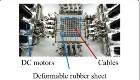
A 3D skin-shape reproduction device, shown in Fig. 3, was previously developed [23]. It consists of 18 DC motors (RE30, Maxon Motor, Switzerland), 18 cables aligned in a grid, and a silicon rubber sheet. Shape repro-duction proceeds as follows: First, the deformable rub-ber sheet is inflated by air injected from the bottom of the deformable area, with inflation of the rubber sheet restricted by adding tension to each cable by winding them up using the motors. A variety of surface shapes can be reproduced by adjusting the length of each cable. In our previous study, it was confirmed that this device can reproduce a variety of deformation patterns [23].
Fig. 1 Wounds risk evaluation process [19] Fig. 2 Safety test with variable shape dummy
Shape reproduction process
Skin-shape reproduction is achieved via the process shown in Fig. 4. First, an objective shape, which corre-sponds to the deformation part of the human dummy, is obtained. Next, the length of each cable is calculated as the length of the pathways, which connect the ends of each cable, on the surface of the objective shape. The calculated lengths become the target value of each cable. Then, after initial pressure and pretension are applied to the device, the tension of the cables is optimized to achieve the target length.
Validity of generated surface shape and elasticity as a human dummy
Reproduction of human pelvis
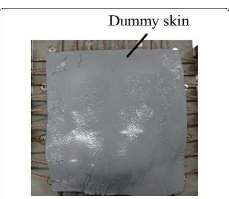
The validity of the surface shape of the device was tested by comparing the surface shape of the device and the tar-get shape obtained from a human. In this study, the part around the anterior superior iliac spine (ASIS), in which the bone is pointed, as shown in Fig. 5, was set to the target shape. Fig. 6 shows the reproduction area and the reference coordinates. The reproduction area is defined as the area surrounded by the red line considering the wound risk and the configuration or the general wearable robot. An example of the shape reproduction is shown in Fig. 7. The figure shows dummy skin made from urethane gel, which mimics the characteristics of human tissue, fixed onto a rubber sheet. Thus, the bumps of the surface
of the membrane formed by cables does not affect the surface shape of the device. The values for the mechanical parameters of the device were set as displayed in Table 1. The size of the surface and the distances between cables were designed to set in a convex of the human body.
Fig. 4 Skin‑shape reproduction process
Fig. 5 Example of human shape (pelvis) [24]
Fig. 6 Human shape reproduction area and coordinates
Confirmation of shape reproducibility
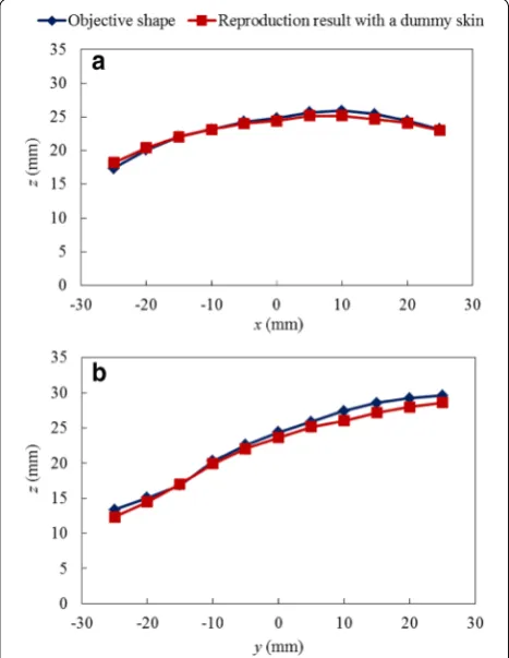
For the validation check of the shape reproduced using the device, the displacement and curvature of the device and target shape were compared in Figs. 8 and 9. The shape of the device was measured using a 3D scanner. In the figures, the comparison was conducted at y =
5 mm and x = 5 mm, where the curvature was largest. The graphs show that the device reproduced the feature of the target shape-in this case, the local bulge. Thus, in this study, the reproduced shape was determined as the baseline shape. Then, shapes slightly deformed from the baseline shape were used to evaluate the effect of the dif-ference of unevenness.
Elasticity of the deformed surface
Because the device comprised the musculoskeletal sys-tem and surface tissue of a human, the deformed surface has to reproduce the mechanical properties of human bone, muscle, and fat. Thus, the elasticity in the nor-mal direction and the shear modulus of the device were measured.
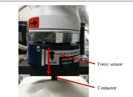
The elasticity in the normal direction was measured using the manipulator shown in Fig. 10. In this method, the contactor attached to the robotic cuff was pushed into the reproduced body. Then, the reaction force applied to the contactor was measured using a force sen-sor. In this experiment, the area of the contactor was 64 mm2 and the indentation force was measured up to a depth of 5 mm. As a result, the normal stress per inden-tation depth was calculated as 64.0 kPa/mm. Although
Dummy skin thickness 3.0 mm
Deformation area (x‑direction) 90 mm
Deformation area (y‑direction) 90 mm
Number of cables (x‑direction) 9
Number of cables (y‑direction) 9
Interval of cables 10 mm
Fig. 8 Displacement comparison results. a Displacement comparison (y = 5), b displacement comparison (x = 5)
Fig. 9 Curvature comparison results. a Curvature comparison (y = 5),
the elasticity in the normal direction around ASIS was not reported previously, the rigidity of the relaxed muscle with a large deformation was estimated at approximately 5.5 kPa/mm using the strain–stress diagram [25]. This suggested that the device was much stiffer than the soft tissue of a human and was closer to that of the part with the thin tissue supported by bone.
The transverse elasticity was also measured, as shown in Fig. 11. In this experiment, the robotic cuff was moved along the shear direction using the manipulator, which was preloaded to avoid slippage. The reaction force in the shear direction was measured with a force sensor. The area of the contactor was approximately 1750 mm2 and the deformation in the shear direction was up to 5 mm. The shear modulus was calculated by dividing the shear stress by the shear strain. The shear strain was calculated by dividing the motion distance of the cuff by the thick-ness of the deformable part of the device. The shear mod-ulus of the device, 7.48 kPa, was relatively close to that of human muscle, 5.40 kPa [26].
Effect of surface shape variability on interaction force
Evaluation process using the surface deformation device The evaluation of the effect of surface shape variability on the interaction force exerted during rubbing motions was conducted using the surface deformation device and the manipulator. As mentioned above, the baseline shape was designed from the 3D shape data around ASIS, acquired from a human. Then, surface shapes with slightly differ-ent gradidiffer-ents from the baseline shape, were designed from the baseline shape. The interaction force when the robotic cuff rubbed these surfaces using the manipulator was measured and compared to each other.
Design of the surface shape variance
It was hypothesized that the shear force on human skin increases when the cuff is over the convex because of larger form resistance and friction. In this study, three shapes, plotted in Fig. 12, were used to evaluate the effect of shape variance. These shapes were designed by modi-fying the ASIS ( x=5 mm and y= −10 mm) part of the baseline shape to increase or decrease its height by ±
1 mm, as shown in Fig. 12.
Experimental protocol
Because the interaction force exerted when rubbing on the uneven surface is affected by the normal force of the robotic cuff, the normal force of the manipula-tor was controlled to 20 N, which was the value exerted at the cuff when using a wearable robot in the previous study [17]. The surface of the robotic cuff was covered by a 40 mm × 40 mm × 15 mm sponge sheet, determined by considering the softness of the cuff used in commer-cial wearable robots. In this study, initially, the center of the robotic cuff was set at x=5 mm and the front edge was set at y= −15 mm. Then, the robotic cuff rubbed the surface along the y-direction, keeping the force in the z-direction constant, as shown in Fig. 13. During
Fig. 10 Measurment of the elasticity in normal direction of the reproduced shape
Fig. 11 Transverse modulus evaluation of the reproduced shape
the rubbing motion, the position of the robotic cuff and interaction force exerted on it was measured. This pro-cess was repeated 10 times for each condition.
Result of experiment
The recorded shear force on the different surface shapes is shown in Fig. 14. This result suggests that the interac-tion force in the shear direcinterac-tion increases with gradient. As hypothesized, this is probably caused by the increase of the form resistance as the gradient increases. Conse-quently, the interaction forces increase when the robotic cuff moved over the convex part of the surface.
The maximum shear forces and stresses observed in the experiments are shown in Table 2. The maximum shear stress changed approximately 10–20% even when the height changed 1 mm, as shown in Fig. 12.
Discussion
Relationship between surface shape and interaction force The exerted shear force shown in Fig. 14 and Table 2 sug-gests that there is a relationship between the pattern of unevenness and the interaction force. First, the interac-tion forces among the different surface shapes did not differ until around y= −8 mm, although the shape under the robotic cuff differed, as shown in Fig. 12. This was probably because the effect of the variance of the surface shape was absorbed by the deformation of the sponge of the robotic cuff. The shear modulus may also have
contributed to this easing. Then, the interaction force started to show the difference among gradient values, as stated above.
When the front edge of the robotic cuff reached approximately y=5 mm, the increase rate of the inter-action force started to decline. In this phase, the partial contact of the robotic cuff, a part of which separated from the surface of the device, was observed. Because the nor-mal force of the robotic cuff is controlled to a constant value, the robotic cuff moved upward when getting over the convex. Finally, the interaction force of the baseline shape and large gradient shape started to decrease after y=10 mm. Although the shear force did not increase, the partial contact probably causes stress concentration, which could not be observed even using this measure-ment system.
Because the target of this study was to identify the increase of the wounds risk caused by the variance of sur-face shape when using the wearable robot, some features of the contact state between the robot and human, such as the shape and stiffness of the robotic cuff, viscoelastic-ity of the wearer’s tissue, and the loading pattern of the robotic cuff on the surface, were simplified. Thus, more precise experimentation and analysis is required for prac-tical validation testing of the wearable robot. However, the necessity of considering the surface shape and its var-iance based on the human were expounded in this study.
Fig. 13 The rubbing motion using the manipulator
Fig. 14 Interaction force pattern in the shear direction
Table 2 Maximum shear forces and stresses in the experiments
Shape Maximum shear force
(N) Maximum shear stress (kPa)
Gradient (large) 23.5 14.7
Actual human shape 21.7 13.6
Effect of surface shape variance from the viewpoint of contact safety
When evaluating the risk that appears after several expo-sures to the hazard, the method using the threshold curve is commonly used. By using the threshold curve, the endurance time, which is the threshold time of accept-able risk, can be estimated under specific loading condi-tions. Thus, using the curve that evaluates the wounds risk caused by continuous rubbing [27], the endurance time under various surface shapes was estimated and compared.
The shear force exerted in rubbing motions increases with the normal force. According to previous study [17], the normal force exerted when using a wearable robot seldom exceeded 50 N. Thus, in this section, consider-ing the severe condition when usconsider-ing the wearable robot, a rubbing motion under 50 N of normal force was assumed. In addition, because of the limitation of the specification of the device, it was difficult to keep the surface shape under such a large compression force. Thus, the shear force under the normal force of 50 N was estimated by increasing the pattern of the interaction force observed in the experiment mentioned above proportionally.
The estimated maximum shear stress and the endur-ance time under such a condition area displayed in Fig. 15 and Table 3. The risk curve displayed here was obtained from the rubbing test using porcine skin and human skin [27]. These results suggest that the endur-ance time significantly changes even when the surface shape changes only slightly. In addition, the risk curve used in this study did not include the effect of local stress concentration. As mentioned above, it suggests that the stress concentration occurs over the large convex. More-over, the existence of stress concentration was verified by visualizing the pressure distribution on the surface of the device. A tactile sensor sheet (I-SCAN, Nitta Cor-poration, Japan), which could measure the normal force
exerted on square cells lined on the surface, was used. By putting this flexible sheet on the uneven surface, the concentration of normal force was roughly observed via a rubbing test. The observed force concentration made the endurance time short, as shown in the risk curve.
For the safety design of the cuff of the wearable robot, the increase and concentration of shear force around the convex will cause a problem. Thus, it seems better to use maximum pressure instead of mean value when evaluat-ing the contact force under the robotic cuff. Furthermore, the shape of robotic cuff should probably be designed to decrease the pressure exerted around the body convex. One option is to support the interaction force with a flat area of the body surface. In addition, the contact between flat cuff and body convex such as the situation of this study was not suitable from the view of contact safety. Thus, the area of robotic cuff, which contacts the body convex, should have sufficient indentation to avoid force concentration. However, it should be noted that the index to evaluate the body convex, which could be used to esti-mate the range of individuality, was not determined yet.
Conclusion
The effect of surface shape variance of the human body on the interaction force at the contact area when using a wearable robot was estimated in this study. For this purpose, a device that can mimic the unevenness and variance of the human shape, was developed. Then, the performance of the device was confirmed by compar-ing the characteristics of the device to that of an actual human. Because of the greater unevenness and individu-ality of the surface shape, the experiment, which mim-icked the contact between the human body and the cuff of the wearable robot, targeted the ASIS of the human. The result of the rubbing test using the device and the robotic cuff attached to the manipulator suggests that the interaction force applied to the surface changed approx-imately 10% as the height at the iliac spine changed
±1 mm. Furthermore, this difference probably affects the endurance time, which is an index of the contact safety, significantly under the severe condition. Thus, this study suggests that considering the individual difference in the
Fig. 15 Threshold curve for blister generation [27]
Table 3 Change of safety condition caused by the change of shapes under the 50 N indentation force
Shape Maximum shear
stress (kPa) Endurance time (s)
Gradient (large) 36.8 453
Actual human shape 33.9 676
Acknowledgements
This study is based on the results of research and development of Japan Agency for Medical Research and Development (Project to Promote the Development and Introduction of Robotic Devices for Nursing Care).
Competing interests
The authors declare that they have no competing interests.
Publisher’s Note
Springer Nature remains neutral with regard to jurisdictional claims in pub‑ lished maps and institutional affiliations.
Received: 20 April 2018 Accepted: 24 August 2018
References
1. Lo HS, Xie SQ (2012) Exoskeleton robots for upper‑limb rehabilitation: state of the art and future prospects. Med Eng Phys 34(3):261–268 2. Mohammed S, Amirat Y, Rifai H (2012) Lower‑limb movement assistance
through wearable robots: state of the art and challenges. Adv Robot 26(1–2):1–22
3. Yu H, Choi IS, Han K‑L, Choi JY, Chung G, Suh J (2015) Development of a stand‑alone powered exoskeleton robot suit in steel manufacturing. ISIJ Int 55(12):2609–2617
4. Nabeshima C, Kawamoto H, Sankai Y (2011) Typical risks and protective measures of wearable walking assistant robots. In: System integration (SII), 2011 IEEE/SICE international symposium on, pp 914–919 5. Nabeshima C, Kawamoto H, Sankai Y (2012) Strength testing machines
for wearable walking assistant robots based on risk assessment of robot suit hal. In: Robotics and automation (ICRA), 2012 IEEE international conference on, pp 2743–2748
6. ISO (2014) I.S.O.: Robots and robotic devices—safety requirements for personal care robots. ISO, Geneva
7. Yan T, Cempini M, Oddo CM, Vitiello N (2015) Review of assistive strate‑ gies in powered lower‑limb orthoses and exoskeletons. Robot Auton Syst 64:120–136
8. Chen B, Ma H, Qin L‑Y, Gao F, Chan K‑M, Law S‑W, Qin L, Liao W‑H (2016) Recent developments and challenges of lower extremity exoskeletons. J Orthop Transl 5:26–37
9. Del‑Ama AJ, Koutsou AD, Moreno JC, De‑Los‑Reyes A, Gil‑Agudo Á, Pons JL (2012) Review of hybrid exoskeletons to restore gait following spinal cord injury. J Rehabil Res Dev 49(4):497–514
of a novel test method for skin safety verification of physical assistant robots. In: Rehabilitation robotics (ICORR), 2015 IEEE international confer‑ ence on, pp 319–324
15. Lenzi T, Vitiello N, De Rossi SMM, Persichetti A, Giovacchini F, Roccella S, Vecchi F, Carrozza MC (2011) Measuring human–robot interaction on wearable robots: a distributed approach. Mechatronics 21(6):1123–1131 16. Akiyama Y, Yamada Y, Ito K, Oda S, Okamoto S, Hara S (2012) Test method
for contact safety assessment of a wearable robot‑analysis of load caused by a misalignment of the knee joint. In: RO‑MAN, 2012 IEEE, pp 539–544 17. Akiyama Y, Okamoto S, Yamada Y, Ishiguro K (2016) Measurement of con‑
tact behavior including slippage of cuff when using wearable physical assistant robot. IEEE Trans Neural Syst Rehab Eng 24(7):784–793 18. Akiyama Y, Yamada Y, Okamoto S (2015) Interaction forces beneath cuffs
of physical assistant robots and their motion‑based estimation. Adv Robot 29(20):1315–1329
19. Yoshida K, Yamada Y, Akiyama Y, Hara S, Okamoto S (2015) Development of a safety validation test equipment for severity estimation of wounds caused by physical assistant robot. In: Proceedings of the RSJ/SICE/ JSME 20th robotics symposia, Karuizawa, Nagano, Japan, pp 483–488 (in Japanese)
20. Azouz ZB, Rioux M, Shu C, Lepage R (2004) Analysis of human shape variation using volumetric techniques. In: Proceedings of international conference on computer animation and social agents, pp 197–206 21. Aso M, Yamada Y, Yoshida K, Akiyama Y, Ito Y (2013) Evaluation of the
mechanical characteristics of human thighs for developing complex dummy tissues. In: Robotics and biomimetics (ROBIO), 2013 IEEE interna‑ tional conference on, pp 1450–1455. IEEE
22. Carbone G, Lorenz B, Persson B, Wohlers A (2009) Contact mechanics and rubber friction for randomly rough surfaces with anisotropic statistical properties. Eur Phys J E 29(3):275–284
23. Sakai Y, Akiyama Y, Yamada Y, Okamoto S (2018) A three‑dimensional skin‑ shape reproduction mechanism for evaluating the risk of wounds when using a wearable robot. SICE J Control Meas Syst Integr 11(2):128–135 24. Human body shape database 2004–2006. Research Institute of Human
Engineering for Quality life. https ://www.hql.jp/datab ase/cat/size/size2 004(in Japanese)
25. Isogai K, Okamoto S, Yamada Y, Ayabe R, Ohtawa K (2015) Skin‑fat‑muscle urethane model for palpation for muscle disorders. In: System integration (SII), 2015 IEEE/SICE international symposium on, pp 960–964
26. Gennisson J‑L, Deffieux T, Macé E, Montaldo G, Fink M, Tanter M (2010) Viscoelastic and anisotropic mechanical properties of in vivo muscle tissue assessed by supersonic shear imaging. Ultrasound Med Biol 36(5):789–801

![Fig. 15 Threshold curve for blister generation [27]](https://thumb-us.123doks.com/thumbv2/123dok_us/887158.1586126/7.595.57.292.551.698/fig-threshold-curve-for-blister-generation.webp)
