RESEARCH ARTICLE
Modeling and control of electroadhesion
force in DC voltage
Taku Nakamura
*and Akio Yamamoto
Abstract
In this paper, a new model for electroadhesion between two surface-insulated plates under DC electric field is pre-sented and control of dynamic responses of electroadhesion force is discussed. Under DC electric field, even if the voltage difference between the plates is constant, electroadhesion force increases or decreases over time depend-ing on the insulatdepend-ing materials. The increase had been explained by Johnsen–Rahbek (JR) model, but the decrease had not been focused or modeled by physically meaningful way. In addition, the previous models did not explicitly consider the mechanical behaviors of the electrodes, although the mechanical behaviors considerably affect the response. In this work, we introduced a new model that combines both electrical and mechanical behaviors. The elec-trical part, which is based on JR model, explained the force decrease under DC field, in addition to the force increase that had been explained using JR model. The mechanical part was represented by a combination of a spring and a damper. Numerical simulations using the model successfully reproduced characteristics behaviors of electroadhesion force, which include force decay under constant voltages and relatively smaller initial force. Using the inverse model, we carried out experiments to control dynamic responses of electroadhesion force, which successfully controlled force responses against pulse voltages. Through the experiments, we also showed the importance of the neutraliza-tion of surface charges for obtaining reproducible responses.
Keywords: Electrostatic adhesion, Bilayer dielectric, Interface charge, Johnsen–Rahbek effect, Built-in sensor, Haptic display
© The Author(s) 2017. This article is distributed under the terms of the Creative Commons Attribution 4.0 International License (http://creativecommons.org/licenses/by/4.0/), which permits unrestricted use, distribution, and reproduction in any medium, provided you give appropriate credit to the original author(s) and the source, provide a link to the Creative Commons license, and indicate if changes were made.
Background
Two surfaces having different electrical potentials stick
to each other by electrostatic force, which is called
elec-troadhesion. The electroadhesion has been utilized for various applications. The early application is electrostatic
chucks for handling silicon wafers [1, 2] or glass
sub-strates in IC or LCD production lines. Recently, the appli-cation areas of the electroadhesion have been expanding to robotics and haptics. In robotics field, researchers have proposed unique applications such as
wall/ceiling-attach-ment for drones [3], soft grippers [4], and wall-climbing
robots [5–9], as the electroadhesion can be realized with
a simpler and lighter devices compared to other adhesion
methods [5, 6, 10]. For those robotic applications,
inter-digital electrodes have been preferred due to its adhesion
capability to dielectric surfaces. The behavior of inter-digital electrodes in the context of electroadhesion has
recently been studied extensively [8, 11, 12].
Electroad-hesion has also been applied to surface haptic displays
[13–18], in which electroadhesion modulates friction on
a transparent electrode that covers an LCD surface, to create haptic effects. In those haptic applications, planar electrodes have been preferred, rather than inter-digital electrodes.
In these relatively new application fields, especially in the field of haptics, control of dynamic responses of electroadhesion force is required. To facilitate dynamic response control, an electric model that can describe the internal electric effect needs to be developed. In the con-ventional electrostatic chucks for wafer handling, elec-troadhesion force gradually increases under a DC voltage, which is called Johnsen–Rahbek (JR) effect. This JR effect is due to the conductivity of the surface insulators. The resulting electroadhesion force grows considerably large,
Open Access
*Correspondence: [email protected]
much larger than typical electrostatic attraction force cal-culated using the text-book parallel plate model. Wata-nabe et al. developed an electric model to describe JR
effect [19], which has been extensively utilized in
analyz-ing the conventional electrostatic chucks [20, 21].
On the other hand, studies in the field of haptics reported that their electroadhesion force decreases
under a constant DC voltage applications [13, 16, 22]. In
those studies, less conductive materials are used as sur-face insulators, whereas electrostatic chucks intention-ally add some conductivity to the insulating materials. To explain the decreases, those studies tried to develop different electric models. However, although those mod-els successfully reproduced the force decrease, they do not explain the electroadhesion phenomena in a physi-cally meaningful way. In addition, electroadhesion often involves mechanical responses of the electrodes. There-fore, electric model alone is not enough; an electro-mechanical combined model is required for dynamic response control.
Although fast and accurate control of electroadhesion force, especially under DC voltages, is imperative in the field of haptics and robotics, it has been a challenging issue, due to the lack of reasonable models. In this paper, we propose an electro-mechanical model for electroad-hesion and demonstrate dynamic control of electroadhe-sion force using the inverse of the proposed model. The electric part of the proposed model is based on JR model. In this work, we have analyzed the JR model developed by Watanabe to show that it can also explain the force decreases observed in haptic studies. One of the reasons that the previous studies failed to model the electroad-hesion would be unstable behaviors of electroadelectroad-hesion device. This paper points out that the unstable behaviors originate in the initial electric charges on the surface of the electroadhesion device. Our experiments have shown that stable behaviors are obtained by removing the ini-tial surface charges. Finally, we have demonstrated that dynamic response of the electroadhesion can be con-trolled based on the proposed electro-mechanical model.
The structure of this paper is as follows. “Related
work” reviews issues on modeling and control of
elec-troadhesion. “Electroadhesion model” introduces an
electro-mechanical combined model. “Control of
elec-troadhesion” demonstrates the force control based on the
model. “Discussion” denotes limitations of the model and
the experiments. “Conclusion” summarizes this paper.
Related work
The simplest model for electroadhesion is the parallel-plate-capacitor model. Assuming a pair of electrodes insulated by one or more dielectrics, the model expresses
electroadhesion force Fe as
where ε0 is the absolute permittivity of vacuum, A is the
area of the electrode, and V, dˆ are the voltage
differ-ence and the equivalent gap between the electrodes. This model is often used for simple estimation of the
adhe-sion force [23]. However, it is only valid in a steady state
of AC voltage condition. Therefore, previous studies that required electroadhesion force control often resorted to AC voltages, instead of using DC (or low frequency AC)
voltages, such that they can rely on this simple model [14,
16].
Due to mechanical and electrical responses, the actual generated force changes dynamically. The mechanical response is caused by elastic deformation of asperity in
surface roughness [21] and macroscopic deformation of
the electrodes/insulators [17]. In the previous study, the
authors showed that the mechanical responses can be compensated by estimating the equivalent gap by using a built-in sensor that measures the capacitance of the
paired plates [18].
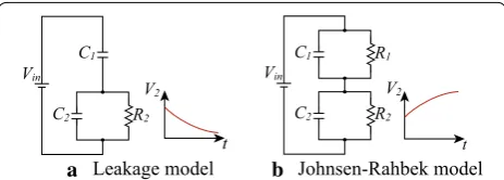
Regarding the electrical response, two different
mod-els have been mainly studied. One is leakage model [24,
25] that can explain decrease of electroadhesion force
observed in haptic studies [13, 16, 22]. In the leakage
model, the paired electrodes have two dielectrics and one of them has a leak resistance as shown in the
equiva-lent circuit of Fig. 1a. By focusing on the voltage across
the leakage-side dielectrics (V2), the model can explain
the force decrease. Although the model can reproduce the experimentally observed force variations, corre-spondence between the model and the actual setup, or the physical background of the model, remains rather unclear compared to JR model explained in the next.
The other model is JR model. Since its first report
in [26], the increase of the force has been explained by
charge accumulation at the borders of the microscopic air gap. When the dielectrics between the paired electrodes have conductivity, charges are accumulated and held by the gap, resulting to the force increase. This model
is expressed as the equivalent circuit in Fig. 1b [19–21],
which consists of an air-gap and conductive dielectric (1) Fe=
1 2ε0A
V
ˆ
d 2
,
C1
R2 C2
Vin
Leakage model
V2
R2 C2
R1 C1
Vin
V2
t t
Johnsen-Rahbek model
a b
layers. The air gap is also assumed to have conductivity corresponding to the contact resistance. By calculating the adhesion force from the voltage across the air gap, the model can explain the force increase. However, our observations in our previous studies indicated that the responses of electroadhesion force cannot be perfectly explained with these electrical models alone; mechanical behavior needs to be taken into account.
Electroadhesion model Concept
In this work, we propose an electro-mechanical model for electroadhesion, with a special focus on force decreasing type. Although, the previous studies have tried to explain the force decrease by the leakage model, this work adopts JR model as it has better physical background.
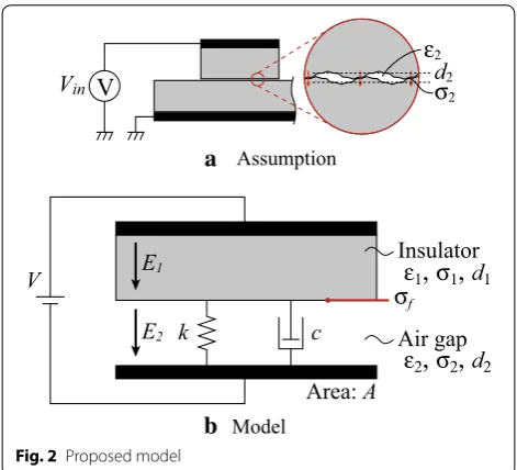
In Fig. 2a, our assumption for the air gap is illustrated.
A basic electroadhesion mechanism consists of a pair of surface-insulated electrodes. The insulators are a die-lectric material but has a slight edie-lectrical conductivity. Between the contact surfaces, there is an air gap due to surface roughness and macroscopic deformation of the electrodes. This air gap behaves like a dielectric material having a slight electrical conductivity since charge relaxa-tion occurs between the contact surfaces.
Based on the assumption, this work models the troadhesion mechanism as a bilayer dielectric with
elec-tric loss as shown in Fig 2b. The two insulators on actual
setups are summarized into one insulating layer in this model for simplification. The model shares the same
concept with the JR model developed by Watanabe [19].
However, our model includes the mechanical aspect
represented by the spring (spring constant: k) and the
damper (damping constant: c), as shown in Fig 2b. To
facilitate the combination with the mechanical aspect,
our model focuses on electric field, E, whereas
Watan-abe’s JR model focuses on voltages.
The model consists of two dielectric layers: insula-tion layer and air-gap layer. Each layer, referred by index
i (i=1 insulation layer, 2 air-gap layer), has a uniform
absolute permittivity εi, electrical conductivity σi, and
thickness di. From the difference of the conductivity,
interface charge σf accumulates at their interface, and
thus the electric field of each layer, Ei, changes over time.
Electroadhesion force, Fe, can be derived from the
Max-well stress of the air gap as
where A is the area of the electrode. For ease of
analy-sis, distortion of electric field at the edge of the plate is ignored.
Differential equation
First, we analyze the model under a constant gap, to ver-ify that electric behavior of the model can describe the decrease of the electroadhesion force; the spring and the damper representing mechanical responses are ignored at this step. First, a differential equation for the electric field of the air gap is derived. Charge conservation at the interface provides
where Ji is the current density in each dielectric.
Assum-ing Ohm’s law, J =σE, the above equation becomes
The boundary condition is expressed as
where V is the applied voltage. From Eqs. (4) and (5), the
differential equation for E2 is derived as
A symmetric equation can be derived for E1.
DC behavior
Assuming that V =V0 is applied during t≥0 and there
is no initial charge at t=0, Eq. (6) is solved as
(2)
Fe= 1
2ε2A E2(t) 2,
(3)
J1−J2= − ∂
∂t(ε1E1−ε2E2),
(4)
σ1E1−σ2E2= − d
dt(ε1E1−ε2E2).
(5)
V =E1d1+E2d2,
(6) (ε1d2+ε2d1)dE2
dt +(σ1d2+σ2d1)E2=σ1V+ε1 dV
dt. Assumption
Model
ε1
,
σ1,
d1ε2
,
σ2,
d2σf
Area: A
k c
E1
E2
V
Vinε2 σ2
d2
V Insulator
Air gap
a
where τ is the time constant denoted as
Equation (7) consists of two terms: incremental term
related to the conductivities and decremental term related to the permittivity. When the former term is dominant, the resulting behavior becomes JR effect, where electroadhesion force gradually increases. On con-trary, if the latter term becomes dominant, this model should be able to describe the force decreasing phenom-enon reported in haptic studies.
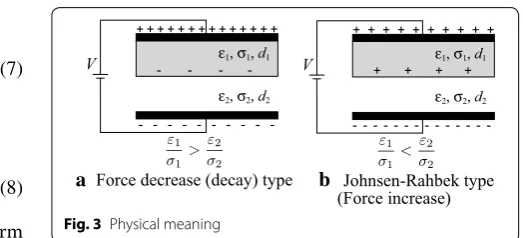
The condition that defines the dominant term, can be obtained by calculating the interface charges. The
inter-face charges, σf(t), are calculated as
Depending on the sign of the numerator of the right-hand side of the equation, the interface charges become either
negative or positive, as shown in Fig. 3 (the figure depicts
V0>0 condition). When the interface charges are
nega-tive, the field of the air gap, E2(t), decreases, which results in
decrease of electroadhesion force, and vice versa. Therefore, the conditions for the two responses can be expressed as:
It should be noted that the response considerably depends on the initial interface charges. If there are
ini-tial charges, σf �=0, at t=0, the electric field changes as
This clearly shows that the response of electroadhesion force, especially the second term, depends on the ini-tial charge. It does not simply change the force response when voltage is applied. It also changes the response at voltage cut-off. When the voltage is turned off, the inter-face charges accumulated during the voltage application
will cause residual adhesion force, as V =0 does not
result in zero field in the equation. Such residual force is well-known in Johnsen–Rahbek-type electrostatic chuck
[20] and also observed in haptic devices [16, 22].
(7)
E2(t)= σ1
σ1d2+σ2d1V0
1−e−tτ
+ ε1
ε1d2+ε2d1V0e
−τt,
(8)
τ = ε1d2+ε2d1
σ1d2+σ2d1
.
(9) σf(t)= −ε1E1(t)+ε2E2(t)
= σ1ε2−σ2ε1
σ1d2+σ2d1V0
1−e−τt
. (10)
Force decrease:�ε1σ1 > ε2σ2
�
,
Force increase(JR effect): � ε1 σ1 < ε2 σ2 � . (11) E2(t)=
σ1 σ1d2+σ2d1
V0
1−e−τt
+ ε1V0+σf(0)d1
ε1d2+ε2d1 e−τt.
AC behavior
When AC voltage, V =V0sinωt, is applied and its
fre-quency satisfies ω≫ 1τ, the electric field becomes
which means interface charge does not accumulate in the AC case. As a result, the adhesion force is calculated as
This adhesion force equals to that calculated using the
parallel plate model, Eq. (1), as ε2=ε0.
Numerical simulation with mechanical response
In the actual systems, the air gap between the two plates fluctuates due to microscopic and/or macroscopic defor-mation of the electrodes. If the electroadhesion force changes rapidly, air damping by squeeze effect would also affect. In the proposed model, those gap variation is rep-resented by the spring and the damper. The electroadhe-sion force compresses the air gap supported by the spring
and the damper, and changes the air gap length, d2, in the
model.
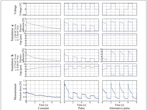
The total response of the proposed model was
numeri-cally simulated as shown in Fig. 4, in comparison with the
experimentally measured results which were obtained in
the same setup as in [16]. It should be noted that the
sim-ulation results show the electroadhesion force whereas the experimental results show the friction force caused by electroadhesion. In the simulation, the electrical part
was simulated using Eq. (6), and the mechanical part was
simulated as a simple linear mass-spring-damper system. The simulation (a) utilized a high spring constant such that mechanical response can be ignored. On contrary, simulation (b) utilized a softer spring such that mechani-cal aspect becomes clear. Both simulation results success-fully reproduced the force decay during constant voltage applications. However, simulation (a) failed to reproduce the initial response for the alternative pulse condition. (12) E2(t)≈ ε1
ε1d2+ε2d1V0 sinωt,
(13)
Fe=
1
2ε2A E2(t)
2= A
2ε2
d1
ε1 + d2
ε2 2V
2 V ε1, σ1, d1
ε2, σ2, d2
+ -+ -+ -+ -+ -+ -+ -+ -+ -+ -+ -+ -+ -+
V ε1, σ1, d1
ε2, σ2, d2
+ -+ + + + + + + + + + + + + Johnsen-Rahbek type (Force increase) Force decrease (decay) type
a b
In the experiment, the response to the initial pulse was much smaller than the second and later responses. This was clearly reproduced in simulation (b). In the begin-ning, the gap was still large and the resulting force was small. However, during the first response, charges accu-mulated at the interface created large force at the sec-ond and later pulses. These results show the validity of the proposed model, as well as the benefit to combine mechanical response into JR model.
Control of electroadhesion Concept
To control the electroadhesion force based on the pro-posed model, we need to derive the inverse model. First,
the target field E is obtained as the inverse model of Eq. (2).
(14)
E =
2
ε2A
Fe
Then, the voltage that should be applied is obtained by
solving Eq. (6). The Laplace transform of Eq. (6) is given
as
where E(s) and V(s) are Laplace transform of E2(t) and
V(t), respectively. By solving this equation in terms of
V(s), we obtain
Now, we need to think about the gap d2. The gap is
hid-den and is normally in the order of micro meters, which can be hardly measured by using typical gap sensors. Therefore, when we apply this model to actual systems,
we estimate the gap d2 from the capacitance between
two electrodes. As the relation between the gap and the capacitance is
(15) {(ε1d2+ε2d1)s+(σ1d2+σ2d1)}E(s)=(ε1s+σ1)V(s)
(16)
V(s)= (ε1d2+ε2d1)s+(σ1d2+σ2d1) ε1s+σ1
E(s). 0
1 2
Electro- adhesion [N
]
0 2 4 6 8 10
Gap
[
µ
m]
Simulation
Simulation
Measuremen
t
-300 0 300
Voltage [V
]
0 2 1 3 4
Electro- adhesion [N
]
0 2 4 6 8 10
Gap
[
µ
m]
Time [s] 8
0 2 4 6
Time [s] 8
0 2 4 6
0 2 4 6 8 10
Time [s] 8
0 2 4 6
Voltag
e
Constant Pulse Alternative pulse
0 0.3 0.6 0.9 1.2 1.5
Friction force [N
]
c
: 5.7
x10
3 N
s/
m
k
: 8.0
x10
5 N/
m
c
: 2.0
x10
4 N
s/
m
k
: 1.0
x10
7 N/
m
a
b
Fig. 4 Comparison of simulations (a, b) with friction force measurements. Simulation parameters are ε1:3.1×ε0F/m,ε2:1.0×ε0F/m,
the gap, d2, can be estimated from the measured capaci-tance as
By substituting the estimated d2 into Eq. (16), we can
obtain the reference voltage that should reproduce the given force. It should be noted that, in this proposed con-trol method, the spring and the damper in the electroadhe-sion model are not required, as the gap change is directly estimated by the gap sensor.
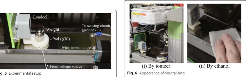
Experimental setup
In order to measure electroadhesion force continuously, indirect measurements through friction change were
con-ducted. The measurement setup is shown in Fig. 5. The
setup, which is basically the same as the one used in [18],
consists of a voltage source, a pad, a motorized stage, a built-in gap (capacitance) sensor, and a loadcell for evalu-ation. The pad (30 mm in diameter and 7 mm in thick-ness), which was fabricated using a 3D printer, was made of ABS resin. The bottom surface of the pad was covered by a
1-mm-thick silicone rubber sheet and then by a 9-µm-thick
PET (polyethylene terephthalate) sheet. The PET sheet had a deposited aluminum layer on its top surface (it should be noted that the bottom surface of the PET sheet touched the stage, which means the aluminum electrode was cov-ered by an insulating PET layer). The stage was a metal plate (stainless steel) whose top surface was covered by an
adhesive PET sheet (Kimoto, PA-8X, 8 µm in thickness) for
insulation. While a voltage for electroadhesion was applied between the pad electrode and the stage, the pad was hori-zontally pushed against the loadcell by the motorized stage, such that the loadcell could measure friction change as the electroadhesion response. The built-in sensor estimated the gap fluctuation through capacitance measurement.
(17)
C= A
d1 ε1 +
d2 ε2 ,
(18) d2=ε2
A C −
d1
ε1
Neutralizing method
In preliminary measurements, we found that the responses of the electroadhesion force was not stable. This would be due to the initial surface charges, as explained in the model. To obtain reproducible results, the initial charges must be neutralized before the experiments.
For neutralization, we tested four different protocols. The
first two protocols utilized an ionizer, as shown in Fig. 6(i).
The ionizer (SUNX, ER-F12) was arranged above the setup and was activated for 2 min for protocol (a), and 15 min for (b). In the protocol (c), we combined the ionizer and etha-nol. After neutralizing surface charges using the ionizer, we gently wiped the surface using a cleaning paper (OZU co., BEMCOT PS-2) impregnated with ethanol as shown
in Fig. 6(ii). The protocol (d) only utilized a cleaning paper
with ethanol; we rubbed the surface by the cleaning paper. The results of force measurement to confirm the effect
of the neutralizations are shown in Fig. 7. The surface of
the setup has been neutralized by the four protocols, four times each. After the neutralization, voltage was applied and electroadhesion force was measured by moving the stage. The protocols (a), (b), and (d) showed unstable responses; the force variations are different among trials. In the protocol (c), on contrary, the force response was sta-ble; it showed the same curve for four trials. Although it is not shown in the figure, we also tested gentle wipe using a cleaning paper with ethanol (without using ionizer) that also showed unstable responses. These results show that the combination of an ionizer and cleaning paper with eth-anol can effectively remove the surface charges.
In these results, protocol (d) showed larger fric-tion force than other protocols. This would be probably because ethanol affected the surface treatment of the film. This suggests that the use of ethanol should be mini-mized to prevent surface damage.
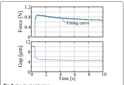
Calibration
After neutralizing the surface charge, a step response of the friction force against a step voltage input was
Loadcell
Pad (φ30) Weight
Motorized stage
From voltage source
To sensing circuit (ground)
Fig. 5 Experimental setup
(i) By ionizer (ii) By ethanol
measured on the stage moving at a constant speed (4 mm/s). The gap variation was measured at the same time
using the gap sensor. The results are shown in Fig. 8.
From these plots, conductivities, σ1,σ2 and friction index
µ were manually obtained, such that the model could
produce the obtained force variation under the meas-ured gap variation. The relative permittivity of the air was assumed to be 1.0, whereas that of the insulating film was set as 3.1, which is a typical value for PET film.
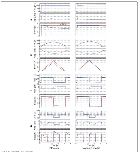
Control of dynamic response
Using the calibrated parameters, force control experiments have been carried out. The temperature was between 18 and 26 °C and relative humidity was between 15 and 30%.
The results are shown in Fig. 9. The two columns show two
different control methods. The first control method on the left column, which is denoted as “PP model”, utilized the
parallel-plate capacitance model as described in Eq. (1).
In this method, the gap was assumed constant and the
applied voltage was determined by solving Eq. (1) under
a constant gap. In the other method on the right column, which is referred to as “Proposed model”, the gap was
esti-mated from the gap (capacitance) sensor [18] and the
volt-age was obtained by using Eqs. (14) and (16).
In plots (a) and (b), the force decay that appeared in PP model was successfully compensated by using the proposed model. As shown in plot (c), PP model showed residual force after cutting off the voltage. On the other hand, in the proposed model, the voltage was not totally cut but was kept at some small value, which resulted in zero residual force. In plot (d), responses against polar-ity-alternating pulses are shown. Although the proposed model showed far improved responses compared to the conventional PP model, the response against the negative pulse showed some deviation. This would be because the
model parameters (σi) were identified for a positive
volt-age. For better force control, a better parameter identifi-cation method needs to be investigated.
Discussions
The model proposed in this paper did not consider the relative motion of the electrodes, although the
elec-trodes were moving during the experiments. In [27], it
has been reported that the electrode motion affected the adhesion force. Since their electrodes were inter-digital electrodes, their results cannot immediately apply to our system. However, their results suggest that the adhesion force would change also in our system. In our system, if the electrodes relatively move, the charges at their
inter-face, σf, would virtually reduce, as the facing areas will
be continuously changing. In other words, the charges accumulated on the stage surface will be left behind
0 2 4 6 8 10
0 0.4 0.8 1.2 1.6
Friction [N
]
Time [s] 0 2 4Time [s]6 8 10
. n i m 5 1 r e z i n o I .
n i m 2 r e z i n o I
a
b
c
Ionizer 3 min. + Ethanol (wipe) Ethanol (rub)d
#1(-350V) #2(-350V) #3(+350V) #4(+350V)0 2 4 6 8 10
0 0.6 1.2 1.8
Friction [N]
Time [s] 0 2 4Time [s]6 8 10
Fig. 7 Results of neutralizing
0 0.4 0.8 1.2
Force [N
]
Fitting curve
0 2 4 6 8 10
Time [s] 0
4 8 12
Gap
[
µ
m]
as the pad moves. The newly facing part does not have accumulated charge, which virtually decreases the
inter-face charge, σf.
In the experiments of this work, this effect was negli-gible, as the parameter identification and control experi-ments were all carried out at the same speed. However, to
cope with various motion speeds, the model needs some modifications such that it can account for the virtual charge decrease due to the relative motions.
The voltages used in the experiments were limited to
±500 V, and most of the measurements were carried out
at around 300–400 V. This voltage range is typical (or PP model Proposed model
0 0.4 0.8 1.2
Force [N]
0 0.4 0.8 1.2 1.6
Force [N]
0 0.4 0.8 1.2
Force [N
]
0 0.4 0.8 1.2
Force [N
]
0 200 400
Volt. [V
]
4 8 12
Gap
[
µ
m]
0 200 400
Volt. [V
]
4 8 12
Gap
[
µ
m]
0 200 400
Volt. [V]
4 8 12
Gap
[
µ
m]
0 -400 400
Volt. [V
]
4 8 12
Gap
[
µ
m]
0 2 4 6 8 10
Time [s]
0 2 4 6 8 10
Time [s]
a
b
c
d
Target
slightly higher) for haptic applications. For robotic appli-cations, however, much higher voltages, such as several kilo volts, are often utilized. It has been experimentally shown that the electroadhesion force does not follow the
square relationship in such a higher voltage range [8].
Therefore, it should be verified in future work if the pro-posed model is valid in higher voltage ranges.
It has also been known that humidity affects the
per-formance of electroadhesion [28, 29]. This would be
because the humidity affects the conductivity of the air gap (and the surface insulator). In the proposed model, if we assume very high conductivity for the air gap, the resulting electroadhesion force vanishes instantly, which
corresponds to the observation in [28]. Such an aspect of
the proposed model also needs to be further investigated in future work.
Conclusion
This paper proposed an electro-mechanical combined model for electroadhesion, which consists of an insulator and an air gap, and realized electroadhesion force con-trol in DC voltage, which was found difficult in the pre-vious studies. The electrical part of the model is based on the JR model, in which interface charges accumulate under a DC voltage. By considering the sign of the surface charges, the model can explain force decrease, which has been observed in haptic device applications. The mechani-cal part simulates fluctuation of the air gap, which affects the dynamic response, since the force magnitude and the time constant depend on the gap. The numerical simula-tions using the combined model successfully reproduced the characteristic behaviors of electroadhesion force. It was also shown that the initial response of the electroadhe-sion force can be reproduced only when mechanical part is actively involved. Using the inverse of the proposed model, as well as a built-in capacitive-type gap sensor, experiments to control dynamic force response were carried out. The experimental results verified that the proposed method can suppress errors due to characteristic behaviors of elec-troadhesion. This work also revealed the importance of surface-charge neutralization for reproducible responses of electroadhesion. These knowledges would contribute to better understanding and controlling of electroadhesion systems, especially for haptic and robotic applications. Authors’ contributions
TN contributed to the modeling, analysis, experiments, and drafting of the manuscript. AY took part in the modeling, interpretation of data, and revising of the manuscript. Both authors read and approved the final manuscript.
Acknowledgements Not applicable.
Competing interests
Both authors declare that they have no competing interests.
Availability of data and materials
The datasets supporting the conclusions of this article are included within the article.
Funding
This work was supported in part by Grant-in-Aid for JSPS Fellows (No. 269272) and Grand-in-Aid for Scientific Research (B) (No. 26280069) from JSPS, Japan.
Publisher’s Note
Springer Nature remains neutral with regard to jurisdictional claims in pub-lished maps and institutional affiliations.
Received: 9 April 2017 Accepted: 6 June 2017
References
1. Wardly GA (1973) Electrostatic wafer chuck for electron beam microfabri-cation. Rev Sci Instrum 44(10):1506–1509
2. McGinty GK (1976) Semiconductor device manufacture. US Patent 3,993,509
3. Graule MA, Chirarattananon P, Fuller SB, Jafferis NT, Ma KY, Spenko M, Kornbluh R, Wood RJ (2016) Perching and takeoff of a robotic insect on overhangs using switchable electrostatic adhesion. Science 352(6288):978–982. doi:10.1126/science.aaf1092
4. Shintake J, Rosset S, Schubert B, Floreano D, Shea H (2016) Versatile soft grippers with intrinsic electroadhesion based on multifunctional polymer actuators. Adv Mater 28(2):231–238
5. Yamamoto A, Nakashima T, Higuchi T (2007) Wall climbing mechanisms using electrostatic attraction generated by flexible electrodes. In: IEEE international symposium on micro-nano mechatronics and human sci-ence, 2007. MHS’07. pp 389–394
6. Prahlad H, Pelrine R, Stanford S, Marlow J, Kornbluh R (2008) Electroadhe-sive robots—wall climbing robots enabled by a novel, robust, and electri-cally controllable adhesion technology. In: IEEE international conference on robotics and automation, 2008. ICRA 2008. pp 3028–3033
7. Wang H, Yamamoto A, Higuchi T (2014) A crawler climbing robot inte-grating electroadhesion and electrostatic actuation. Int J Adv Robot Syst 11:191
8. Koh KH, Sreekumar M, Ponnambalam SG (2014) Experimental investiga-tion of the effect of the driving voltage of an electroadhesion actuator. Materials 7:4963–4981
9. Mao J-B, Qin L, Zhang W-X, Xie L, Wang Y (2015) Modeling and analysis of electrostatic adhesion force for climbing robot on dielectric wall materi-als. Eur Phys J Appl Phys 69(1):11003
10. Guo J, Justham L, Jackson M, Parkin R (2015) A concept selection method for designing climbing robots. Key Eng Mater 649:22–29
11. Chen R, Huang Y, Tang Q (2017) An analytical model for electro-static adhesive dynamics on dielectric sustrates. J Adhes Sci Technol 31(11):1229–1250
12. Bamber T, Guo J, Singh J, Bigharaz M, Petzing J, Bingham PA, Justham L, Penders J, Jackson M (2017) Visualization methods for understand-ing the dynamic electroadhesion phenomenon. J Phys D Appl Phys 50:205304
13. Yamamoto A, Nagasawa S, Yamamoto H, Higuchi T (2006) Electrostatic tactile display with thin film slider and its application to tactile telepre-sentation systems. IEEE Trans Vis Comput Graph 12(2):168–177 14. Bau O, Poupyrev I, Israr A, Harrison C (2010) Teslatouch: electrovibration
for touch surfaces. In: Proceedings of the 23rd annual ACM symposium on user interface software and technology. UIST ’10. pp 283–292 15. Linjama J, Mäkinen V (2009) E-sense screen: novel haptic display with
capacitive electrosensory interface. Presented at HAID 09, 4th workshop for Haptic and audio interaction design, Dresden, Germany
17. Nakamura T, Yamamoto A (2016) A multi-user surface visuo-haptic dis-play using electrostatic frcition modulation and capacitive-type position sensing. Trans Haptics 9(3):311–322
18. Nakamura T, Yamamoto A (2016) Interaction force estimation on a built-in position sensor for an electrostatic visuo-haptic display. ROBOMECH J 3(11):1–11
19. Watanabe T, Kitabayashi T, Nakayama C (1993) Relationship between electrical resistivity and electrostatic force of alumina electrostatic chuck. Jpn J Appl Phys 32(2R):864
20. Kanno S, Usui T (2003) Generation mechanism of residual clamping force in a bipolar electrostatic chuck. J Vac Sci Technol B 21(6):2371–2377 21. Kanno S, Kato K, Yoshioka K, Nishino R, Tsubone T (2006) Prediction of
clamping pressure in a Johnsen–Rahbek-type electrostatic chuck based on circuit simulation. J Vac Sci Technol B 24(1):216–223
22. Giraud F, Amberg M, Lemaire-Semail B (2013) Merging two tactile stimulation principles: electrovibration and squeeze film effect. In: World haptics conference (WHC), 2013. pp 199–203
23. Strong RM, Troxel DE (1970) An electrotactile display. IEEE Trans Man Mach Syst 11(1):72–79
24. Meyer DJ, Peshkin MA, Colgate JE (2013) Fingertip friction modulation due to electrostatic attraction. In: World haptics conference (WHC), 2013. pp 43–48
25. Vezzoli E, Amberg M, Giraud F, Lemaire-Semail B (2014) Electrovibration modeling analysis. In: Haptics: neuroscience, devices, modeling, and applications. Springer, Berlin, pp 369–376
26. Johnsen A, Rahbek K (1923) A physical phonomenon and its applications to telegraphy, telephony, etc. J Inst Electr Eng 61(320):713–725 27. Chen R, Huang Y, Tang Q, Bai L (2016) Modelling and analysis of the
electrostatic adhesion performance considering a rotary disturbance between the electrode panel and the attachment substrate. J Adhes Sci Technol 30(21):2301–2315
28. Tang H, Beebe DJ (1998) A microfabricated electrostatic haptic display for persons with visual impairments. IEEE Trans Rehabil Eng 6(3):241–248 29. Guo J, Bamber T, Chamberlain M, Justham L, Jackson M (2016)