1
Article2
Design,
F
abrication and
A
nalysis of
T
hreshold-
V
alue
3
J
udging
M
echanism in MEMS Safety and Arming
4
D
evice
Dakui Wang 1, Wenzhong Lou 1, Yue Feng 1, * and Fufu Wang 2
5
1 National Key Laboratory of Electro-Mechanics Engineering and Control, School of Mechanical-electronic
6
Engineering, Beijing Institute of technology, Beijing 100081, China; [email protected] (D.-K.W.);
7
[email protected] (W.-Z.L.); [email protected] (Y. F.)
8
2 Technology and Engineering Center for Space Utilization, Chinese Academy of Sciences, Beijing 100081,
9
China; [email protected]
10
* Correspondence: [email protected]; Tel.: +86-18310169212
11
12
13
Abstract: In order to meet the military requirements of the fuze, such as precision strike, efficient
14
mutilates ability and low collateral damages, the microminiaturization is an inevitable trend of
15
secure system. Based on the silicon-based MEMS S&A device designed by our term, the design
16
principles of each module and fabrication process are introduced. The average fracture strength
17
and Young's modulus of the silicon are 726MPa and 175GPa from the tensile test, respectively.
18
From Hopkinson impact experiment, we can get the threshold-value judging mechanism being
19
safety under the impact overload of 20526g, and this value is much more than the standard of the
20
drop overload 12000g; the arming value under the centrifugal overload obtained from theory,
21
simulation and experiment is at the range of 28200g and 32000g, it shows that the threshold-value
22
judging mechanism can be arming compared with the value 35951g of design principle. Therefore,
23
the threshold-value judging mechanism can meet the design requirements of overload.
24
Furthermore, the relationship of fracture threshold-values obtained by different theories is found
25
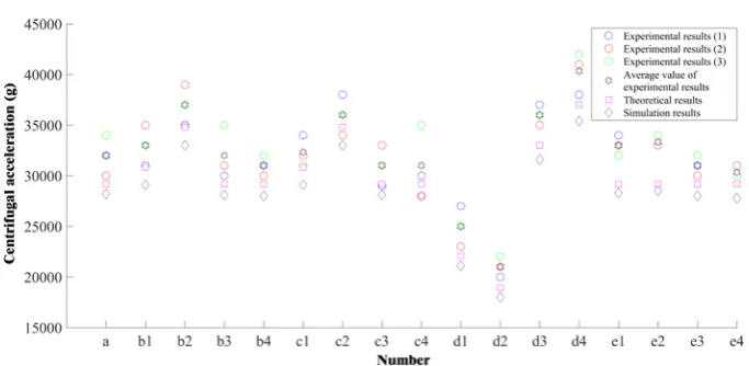
out through parametric design method, as shown in Figure 14, it provides the theory evidence to
26
the follow parametric design.
27
28
Keywords: MEMS S&A device; threshold-value judging mechanism; fabrication process; tensiletest; theoretical, simulation and experimental analysis; parametric design method
29
30
1. Introduction
31
MEMS is a relatively new and fast-growing field in microelectronics [1-3]. MEMS is commonly
32
used as actuators, sensors, and radio frequency and micro fluidic components, as well as
33
bio-composites, with a wide variety of applications in health care, automotive, and military
34
industries. It is expected that the market for MEMS will grow to over $30B by 2050 [4-7].
35
Weapons are mainly mechanical equipment based on the mechanical processing technology in
36
twentieth century, and are quickly into the intelligent, information and miniaturization in
37
twenty-first century [8-10]. The application of MEMS technology is inevitable trend of the
38
development of modern weapons and equipment. With the application of weapon is more widely,
39
fuze as a function module of the weapon, and the function of fuze is more than ever [11]. In order to
40
place more modules in the fuze, it is needed to apply the MEMS technology on the Safety and
41
Arming device, which is the key mechanism about ensuring the safety in handling transportation
42
and storage, meanwhile, it is the reliable arming with the launch overload in fuze [19-21].
MEMS S&A device have obvious advantages compared to the traditional S&A device, such as
44
small size, light weight and low cost [15-18]. The MEMS S&A device can make more space, place
45
more functional modules and decrease the charge, and then improve the accuracy of ammunition,
46
combat power and cost-effectiveness ratio.
47
At present, there are two routes of the miniaturization for the MEMS S&A device [19-21]. One
48
of routes is non-silicon-based route and the other one is silicon-based route. Non-silicon-based route
49
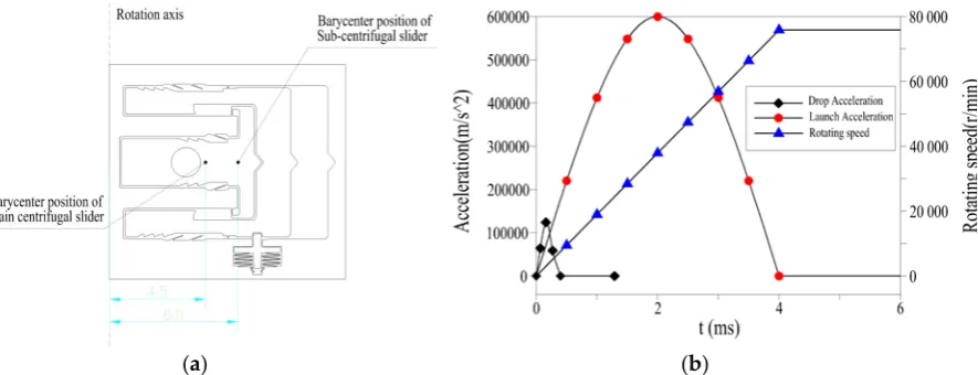
is mainly based on nickel and copper materials with the LIGA or UV-LIAG process, one of the
50
advantages is that it is widely chosen material and can obtain the structure with higher depth and
51
width. One of the disadvantages is that it cannot be integrated processing, and needs
52
micro-assembly tasks. Silicon-based route is mainly based on silicon material with the DRIE or SOI
53
process, the advantages are the process has a good compatibility with the traditional
54
microelectronics process, which can achieve integration of processing and realize the
55
miniaturization. Its disadvantages are that the impact of silicon material is relatively poor [22-24].
56
Silicon-based route is the development direction of the future MEMS S&A device [25-28]. The
57
process of the Silicon-based route can be integrated with microelectronics, and make the S&A device
58
become an independent chip module, and other modules are integrated together to achieve the
59
conception of 'fuze on chip' [29-31]. Aiming at the conception of 'fuze on chip', our term puts
60
forward a silicon-based MEMS S&A device innovatively. At the same time, the mechanical
61
environment sensing layer is fabricated periodically [32-34]. Furthermore, the various modules of
62
the mechanical environment sensing layer should be experimented and simulated.
63
A few works have been carried out for detailed analysis of the mechanical environment sensing
64
layer in MEMS S&A device. This paper aims to verify the feasibility of the designed threshold-value
65
judging mechanism in MEMS S&A device. First, the simplified threshold-value judging mechanism
66
is fabricated and the mechanical properties of silicon materials are tested. Next, the safety of the
67
threshold-value judging mechanism under the drop overload of service processing is confirmed
68
through the Hopkinson impact experiment. Then, the theoretical and simulation models of the
69
threshold-value judging mechanism are established, which the influence of the centrifugal force and
70
the parameters for the threshold-value connection units are parametric studied based on the
71
established models. Finally, the experimental results are presented, and the corresponding
72
theoretical and simulation models are verified quantitatively. The research can provide fundamental
73
knowledge for optimizing model parameters.
74
2. Design and fabrication
75
2.1. Design principles
76
The monolithic structure of silicon-based MEMS S&A device, which our term designed, is
77
shown in Figure 1. The overall size of the silicon-based MEMS S&A device is 11mm×10mm×0.5mm.
78
The MEMS S&A device is mainly used for rotating ammunition, and it is mainly divided into two
79
parts, one is the circuit control layer and the other is mechanical environment sensing layer. The
80
overall size of the circuit control layer is 11mm×10mm×0.1mm, and its function is to realize remote
81
arming and detonate booster explosive. The circuit control layer is mainly composed of a frame, an
82
electrothermal actuator component, a moving slider which is bonded to the main centrifugal slider
83
of the mechanical environment sensing layer at the bottom and a silicon semiconductor bridge is
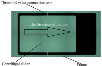
84
used for detonating booster explosive. The overall size of the mechanical environment sensing layer
85
is 11mm×10mm×0.4mm, it is mainly composed of a frame, a inertial safety device, a sub-centrifugal
86
slider, a main centrifugal slider, an impact release mechanism, a threshold-value judging mechanism
87
and a locking mechanism, as shown in Figure 1.
88
The design principles of silicon-based MEMS S&A device are as follows. The inertial safety
89
device and other mechanisms of the mechanical environment sensing layer cannot achieve arming
90
under the condition of extreme drop overload in service processing; under the condition of launch
91
overload (recoil overload and centrifugal force), the inertial safety device, the threshold-value
92
judging mechanism and the impact release mechanism can realize arming in this order. The arming
process of the mechanical environment sensing layer is as follows. Firstly, the slider of the inertial
94
safety device under the recoil overload overcomes the elasticity of the recoil MEMS spring, next
95
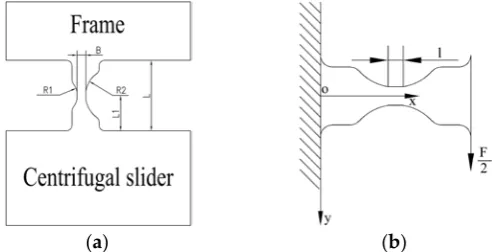
slides to the bottom and is locked at the bottom by the recoil locking mechanism. Then, under the
96
centrifugal force, the connection nodes of the threshold-value judging mechanism fracture, the
97
sub-centrifugal slider move in the direction of the centrifugal force and impact the connection nodes
98
of the impact release mechanism, thus release the main centrifugal slider, At the same time, the
99
sub-centrifugal slider is limited to a predetermined position by a locking mechanism; the main
100
centrifugal slider continues to move in the direction of the centrifugal force under the centrifugal
101
force, finally, it is limited to a predetermined position by a locking mechanism. At this time, the
102
detonation transmission hole is aligned with the electric detonator and the booster pellet, the MEMS
103
S&A device is in readiness. In addition, the barycenter position of the main centrifugal slider and the
104
sub-centrifugal slider, as well as the position of rotation axis for the projectile is shown in Figure 2.
105
The maximum recoil overload, the launching overload pulse width and the maximum rotating
106
speed corresponding to different caliber ammunitions, as described in Table 1. In this study, using
107
35mm caliber ammunition as design criteria, then the overload curve of service processing and
108
launch overload curve, as Figure 2 is shown.
109
(a) (b)
Figure 1. (a) The designed MEMS S&A device; (b) Mechanical environment sensing layer
110
(a) (b)
Figure 2. (a) Barycenter position of the main centrifugal slider and the sub-centrifugal slider, as well
111
as the position of rotation axis for the projectile; (b) The overload curve of service processing and
112
luanch overload curve
113
Table 1. The launch environment of different caliber ammunitions.
114
Ammunition
caliber (mm) Maximum recoil overload (g) pulse width (ms) Launch overload Maximum rotating speed (r/min)
25 59734 4 82286
35 59500 4 73918
130 20000 13 10000
2.2. Fabrication process
115
At present, the mechanical environment sensing layer has been fabricated by bulk silicon
116
processing and bonding technologies. It is mainly composed of a silicon-based mechanical
117
environment sensing layer and the BCB bonded glasses on the upper and the lower sides. Figure 3.
118
shows the micro fabrication process of the mechanical environment sensing layer. The detailed
119
processing technique of the mechanical environment sensing layer is as follows.
120
(a)Wafer preparation. Using silicon wafer as the substrate, the resistivity of the silicon wafer is
121
2~4Ω.cm, and the size is 4 inches;
122
(b)Physical vapor deposition (PVD). Sputtered aluminum layer on the back ;
123
(c)Physical vapor deposition (PVD). Sputtered aluminum layer on the front ;
124
(d)Structural lithography. Graphical fabrication of the structure ;
125
(e)Aluminum corrosion. Graphical fabrication of the front aluminum layer, and the composite
126
mask is formed with the photoresist ;
127
(f)Deep reactive ion etching (DRIE). Graphical fabrication of the silicon wafer (see the Figure
128
4.) ;
129
(g)Photoresist removal. Thoroughly clean the surface of silicon wafer by using concentrated
130
sulfuric acid and hydrogen peroxide ;
131
(h)Wafer preparation. Using glass wafer as the substrate ;
132
(i)BCB lithography. Graphical fabrication of BCB ;
133
(j)BCB bonding. The graphical BCB is bonded to the back of the graphical silicon wafer;
134
(k)Wafer preparation. Using glass wafer as the substrate ;
135
(l)BCB lithography. Graphical fabrication of BCB ;
136
(m)BCB bonding. The graphical BCB is bonded to the front of the graphical silicon wafer, then
137
the three-layer structure of glass-silicon-glass is formed ;
138
(n)Wafer dicing. The whole three-layer structure is divided into multiple independent units.
139
140
(a) (b) (c)
(d) (e) (f)
(g) (h) (i)
(j) (k) (l)
(m) (n)
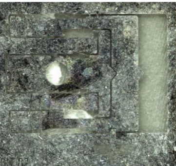
Figure 3. Fabrication process of the mechanical environment sensing layer. (a) Wafer preparation; (b)
141
PVD Al 2um; (c) PVD Al 2000A;(d) Structural lithography;(e) Aluminum corrosion; (f) DRIE; (g)
142
Photoresist removal; (h) Wafer preparation; (i) BCB lithography; (j) BCB bonding; (k) Wafer
143
Figure 4.
Structure of the mechanical environment sensing layer before BCB bonding
145
3. Tests of mechanical properties for silicon materials
146
The tensile test of the micro sample can be carried out by the micro force tensile testing machine
147
(see Figure 5.), and then we can get the mechanical properties of silicon materials. The device is a
148
horizontal tensile testing machine, it can be used to carry out micro force tensile test for various
149
materials and devices, and the equipment is mainly composed of horizontal frame, force sensor,
150
displacement sensor, air supply component, computer control system, fixed stage and so on.
151
152
Figure 5.Schematic view of the testing equipment
153
The micro sample is mounted on the two mechanical fixtures of the loading unit. When the
154
computer sends the commands which is a specific waveform signal to the controller, the signal can
155
be transmitted to the moving end of the loading unit, and drive the moving end of the loading unit
156
to move, then mechanical test of micro specimen is carried out. In this study, the micro samples are
157
taken from the same batch of silicon wafers used in fabrication process. The cross sections of the
158
tested micro sample are 0.3×0.1mm, 0.4×0.1mm, 0.5×0.1mm and 0.6×0.1mm, respectively; the lengths
159
of the tested micro sample are 1.5mm and 2.4mm, respectively. The cross sections and the lengths of
160
the micro sample are freely combined, and 8 groups of tests are carried out. One of the stress-strain
161
curves of the micro sample during micro force tensile test is shown in Figure 6. Therefore, according
162
to the stress-strain curves of the micro sample, we can get the young's modulus and fracture strength
163
of the silicon. Computing the average of the 8 groups of test results, we can get the average young's
164
modulus of the silicon material is E=175GPa, and average fracture strength is σs=726Mpa.
165
Figure 6. The stress-strain curve of the micro sample
167
4. Simulation, theory and experiment
168
In this paper, the threshold-value judging mechanism is taken as the research object. Based on
169
the theory analysis, simulation analysis and experimental analysis, the response characteristics and
170
the fracture mechanisms of the threshold-value judging mechanism are studied under the overload.
171
In order to improve the design efficiency and shorten the research period, the threshold-value
172
judging mechanism is simplified reasonably, according to the actual situation. The simplified
173
threshold-value judging mechanism is fabricated, its main components are the centrifugal slider,
174
threshold-value connection units and frame, as shown in Figure 7. The role of the threshold-value
175
judging mechanism is as follows. In the usual state of service processing, when the ammunition
176
accidentally falls or rolls , the centrifugal slider can be kept in the original position because of the
177
constraint of the threshold-value connection units in the threshold judging mechanism. Thereby, it
178
can ensure the safety of the MEMS S&A device when the inertial safety device arming unexpected.
179
In the process of launching, the centrifugal slider of the threshold-value connection units leads to the
180
fracture failure under the centrifugal force, and the centrifugal slider starts to move, thereupon, it
181
can ensure the reliability of the MEMS S&A device.
182
183
Figure 7.The fabricated threshold-value judging mechanism
184
4.1. Theory analysis
185
The threshold-value judging mechanism is a symmetric structure as shown in Figure 8. When
186
the threshold-value judging mechanism is subjected to centrifugal acceleration overload, we can
187
carry out the force analysis on one side of the structure.
188
Assuming that the centrifugal acceleration overload is
a
, then the centrifugal force of the189
centrifugal slider suffered is
190
ma
=
F
. (1)The weak link of the threshold-value judging mechanism is the threshold-value connection
191
units. Therefore, the complex stress problem of the threshold-value judging mechanism can be
simplified to the stress problem of the threshold-value connection units. Thereinto, the force of a
193
threshold-value connection unit suffered is
194
2
2
F
/=
F
=
ma
. (2)Assuming that the size of the threshold-value connection units designed actually is shown in
195
Figure 8, the minimum cross section of the threshold-value connection unit is actually a uniform
196
beam because of the limitation of fabrication process. The stress analysis of the threshold-value
197
connection unit is shown in Figure 8.
198
199
(a) (b)
Figure 8. (a) The parameters of the threshold-value connection unit; (b) The parameters and the
200
stress analysis of the threshold-value connection unit.
201
Wherein, the span of the beam is
L
,L
1
is the distance between the center of the circle arc and202
the root of the beam, the width of the minimum section of the beam is
B
, the thickness of the model203
is
H
, and the length of the uniform beam at the minimum section affected by the two circle arc204
radius
R
1
andR
2
isl
.205
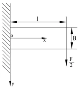
It is a plane stress problem of a cantilever beam with variable cross section, according to the
206
Figure 9. Ignoring the volume force, and assuming that the width of the beam at different sections is
207
( )
x
B
, thus the differential equation of the stress component of the threshold-value connection unit208
is as follows.
209
(
)
=
+
∂
∂
+
∂
∂
=
∂
∂
+
∂
∂
=
∂
∂
+
∂
∂
0
0
0
2 2 2 2 y x xy y xy xy
x
x
y
y
x
σ
σ
τ
σ
τ
σ
. (3)
The boundary conditions are as follows.
210
( ) ( )( )
=
=
±
=
=
=
=
=
=
=
∫
−0
,
0
:
2
1
2
,
0
:
0
,
0
:
0
2 2 xy y x B x B xy xx
B
y
F
dy
l
x
v
u
x
τ
σ
τ
σ
. (4)We can get the Eq.5 by the Eq.3 and theEq.4.
(
)
( )
−
=
=
−
−
=
2 24
4
0
2
y
x
B
I
F
y
I
x
L
F
z xy y z xτ
σ
σ
. (5)
Wherein ,
z
I
is the moment of inertia of the threshold-value connection unit. Because the cross212
section is rectangular, we can get the formula as follows.
213
( )
12
3x
HB
I
z=
. (6)By designing, the threshold-value judging mechanism is a symmetric structure and the
214
centrifugal slider suffers almost all of the force. Moreover, the span of the centrifugal slider is much
215
larger than the span of the threshold-value connection unit, therefore, the shear stress of the beam
216
with variable cross section plays a leading role.
217
( )
−
=
2 24
4
y
x
B
I
F
z xyτ
. (7)We can get the Eq.8 by takingEq.6 into Eq.7.
218
( )
( )
−
=
2 2 34
4
3
y
x
B
x
B
F
xyτ
. (8)If we want to explore the weak point of the variable cross-section beam, it needs to get the
219
maximum value of
τ
xy. Becausex
andy
are the independent unknowns, wheny
=
0
, we can220
take the maximum value of
τ
xy.221
( )
x
HB
F
xy4
3
=
τ
. (9)Therefore, we can take the maximum value of
τ
xy as long as theB
( )
x
takes the minimum222
value for this variable cross-section beam.
223
Therefore, the maximum shear stress is as follows.
224
HB
ma
xy4
3
=
τ
. (10)Furthermore, the minimum cross section of the threshold-value connection unit is actually a
225
uniform beam with width of B and length of l because of the limitation of fabrication process.
226
According to the knowledge of mechanics of materials, the bending stress of the threshold-value
227
connection unit is mainly suffered by the uniform beam. In addition, the width of the uniform beam
228
is much less than the width of the other beam in the threshold-value connection unit, so the force
229
analysis of the uniform beam can be simplified to the force analysis of the cantilever beam, as shown
230
in Figure 9.
Figure 9. Mechanics analysis of the uniform beam.
232
The stress analysis of the cantilever beam is almost the same as that of the variable cross-section
233
beam, we won't explore it here. The expression of the bending stress of the uniform beam is as
234
follows.
235
2
3
HB
mal
x
=
σ
. (11)As is stated above, the average fracture strength of the silicon material is
σ
s=
726MPa
. Thus,236
we can obtain the expression of the maximum resultant stress for the minimum cross section by
237
combining
τ
xyandσ
x, and the expression of the resultant stress is shown in Eq.12.238
726MPa
σ
2 2x
s
=
σ
+
τ
xy=
. (12)According to the design,
L
=
0
.
13
mm
=
1
.
3
×
10
−4m
B
=
0
.
015
mm
=
1
.
5
×
10
−5m
,239
m
mm
H
=
0
.
4
=
4
×
10
−4 ,l
=
0
.
013
mm
=
1
.
3
×
10
−5m
, the centrifugal slider mass240
Kg
m
=
5
.
2
×
10
−6 . Thus, we can get the below result.241
2 5
/
10
×
2.9162
a
=
m
s
. (13)Therefore, when the threshold-value judging mechanism is subjected to the acceleration
242
overload of 29162g, the weak links of the threshold-value connection units occur fracture failure.
243
In addition, the distance between the barycenter of the sub-centrifugal slider and the rotation
244
axis of the projectile is
r
=
6
mm
, as can be seen in Figure 2. When the rotation angular velocity of245
the projectile is
ω
, the centrifugal acceleration of the centrifugal slidera
0can be calculated by the246
following formula.
247
2 0
a
=
r
ω
. (13)It is known that the maximum rotating speed of the projectile is 73918r/min, then from above
248
formula we can obtain that the maximum centrifugal acceleration of the centrifugal slider is
249
2 max
0 359508 /
a = m s .
250
Through above analysis and discussion, we can get the result of
a
max0>
a
, so in theory, the251
threshold-value judging mechanism which our term designed can realize reliable arming under the
252
centrifugal overload of the 35mm caliber launching ammunition.
253
4.1. Experimental and simulation analysis
254
The experiment schemes are mainly to achieve the dynamic response characteristics of the
255
threshold-value judging mechanism under the drop overload of service processing and the
256
centrifugal overload of the launching ammunition, as shown in Table 2.
Table 2.
The experiment schemes and the verification contents.
258
Experiment schemes Verification contents
Hopkinson impact
experiment Fracture performance of the threshold-value judging mechanism under the drop overload High speed centrifugal
experiment Fracture performance of the threshold-value judging mechanism under the centrifugal overload
259
According to the characteristics of small size and light weight of the MEMS S&A device, our
260
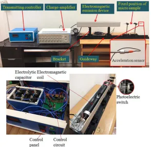
term has designed and built a set of magnetic resistance Hopkinson impact system which has the
261
advantage of adjustable threshold-value, good repeatability and high precision (see Figure 10). The
262
system generates the overload by using the electromagnetic emission device which launches bullet
263
to impact the compressed bar, the impact overload can be up to 45000g, and the experiment
264
frequency is several minutes each time. In addition, in order to meet the requirements of fast
265
experiment of MEMS S&A device, we designed the installation and fixing mechanism of the micro
266
sample according to the content of this experiment, as shown in Figure 11.
267
The working principle of the magnetic resistance Hopkinson impact system is as follows.
268
According to the required overload value, the corresponding charge is added to the electrolytic
269
capacitor, and then connect the electrolytic capacitor to the electromagnetic coil. When the control
270
circuit is identified as a working state, the electrolytic capacitor is instantly discharged to generate a
271
strong current flowing through the electromagnetic coil. A strong magnetic field which is parallel to
272
the coil is generated in the electromagnetic coil, at the same time,the bullet in the electromagnetic
273
emission device is magnetized and then the bullet is ejected. When the bullet is flying out of the
274
electromagnetic emission device, the bullet drives the photoelectric switch to disconnect
275
electromagnetic coil, and finally the bullet impacts the compressed bar which is equipped with
276
micro sample and acceleration sensor.
277
278
Figure 11. The installation and fixing mechanism of the micro sample.
280
As can be seen from Figure 2, the overload peak is 12000g for the drop overload. The impact
281
experiment is carried out on the threshold-value judging mechanism by using the magnetic
282
resistance Hopkinson impact system as shown in Figure 11. In addition, in order to demonstrate
283
whether the design safety margin of the threshold-value judging mechanism is sufficient, the
284
overload peak set between 12000g and 21000g. The motion direction of centrifugal slider under the
285
impact acceleration is shown in Figure 7, and the experiment results are shown in table 3.
286
Table 3. The Hopkinson impact experiment results.
287
Number voltage (V) Charging Peak value (g) Acceleration width (μs) Pulse situation Fracture
1 72 (Single-stage) 14113 50 NO
2 82 (Single-stage) 16155 50 NO
3 91 (Single-stage) 18231 50 NO
4 99 (Single-stage) 20526 50 NO
From the above table, we can see that the threshold-value judging mechanism cannot occur
288
fracture failure when the acceleration peak value is 20526g. Because of the overload peak is 12000g
289
for the drop overload, the designed threshold-value judging mechanism can meet the design
290
requirements of MEMS S&A device and has sufficient design safety margin.
291
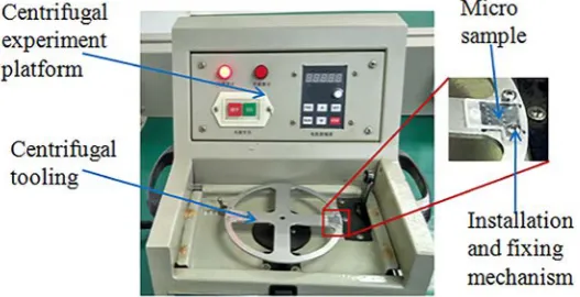
In the case of the threshold-value judging mechanism under the centrifugal overload of the
292
launching ammunition, centrifugal experiments are carried out by using a centrifugal tooling as
293
shown in Fig 12. The maximum rotating speed of the centrifuge is 20000r/min, and the eccentricity of
294
the micro sample is 100. Thus, the maximum centrifugal overload of micro sample is up to 43865g.
295
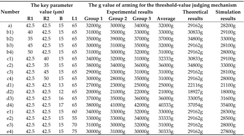
We carried out the parameter design of the threshold-value connection units, and the fabricated
296
threshold-value judging mechanism as shown in Figure 13. We take the centrifugal acceleration of
297
10000g as the initial value and 1000g as step length, and explored the fatigue limit for fracture of the
298
threshold-value connection units as shown in Table 4.
299
The finite element models (see Figure 13) are established by using HyperMesh for the
301
parameterized threshold-value connection units as shown in Table 4. At the same time, according to
302
the theoretical analysis results, we take the centrifugal acceleration of 29000g as the initial value and
303
100g as step length, explore the fatigue limit for fracture of the threshold-value connection units as
304
shown in Table 4.
305
Through theoretical analysis, simulation analysis and experimental study, we can get the
306
results as shown in Table 4 and Figure 14.
307
(a) (b)
Figure 13. (a) Principle prototypes of threshold-value judging mechanism; (b) Finite element models
308
of threshold-value judging mechanism.
309
Table 4. The key parameter values of different threshold-value connection units and the
310
corresponding g values of arming for the threshold-value judging mechanism
311
Number
The key parameter value (μm)
The g value of arming for the threshold-value judging mechanism Experimental results Theoretical
results Simulation results R1 R2 B L1 Group 1 Group 2 Group 3 Average
Figure 14. The g values of arming forparameterized threshold-value judging mechanism.
312
According to Table 4 and Figure 14, the conclusions we obtained is as follows.
313
(1) Through the results of theory, simulation and experiment, we can know that the fracture
314
threshold-value of the threshold-value judging mechanism is 29162g, 28200g and 32000g,
315
respectively, all of which are much less than 35951g of the design principle. The threshold-value
316
judging mechanism meets design requirements of MEMS S&A device.
317
(2) In the same fabrication batch and same design parameters of the threshold-value judging
318
mechanism, there is a larger discreteness in the g values of arming. this conclusion illustrates that the
319
certain discreteness exists in the mechanical properties of silicon material. Therefore, the certain
320
discreteness should be taken into account at the design process.
321
(3) The study shows the theoretical results are higher than the simulation results. The reason is
322
the effect on the structural strength from the structure parameters, such as L1, is ignored and the
323
theoretical calculation is static method.
324
(4) The average experimental results in the study are higher than the theoretical results. This
325
situation is caused by the friction and gas damping existed in micro samples.
326
(5) The theoretical results, the simulation results and the experimental results have a high
327
consistency. The conclusion illustrate we can carry out initial optimization design through the
328
theoretical method.
329
5. Conclusions
330
According to a MEMS S&A device designed by our term, this paper introduces its design
331
principle and fabrication process. At the same time, we also illustrate the design requirements of
332
modules in MEMS S&A device. Taking the threshold-value judging mechanism as the study object,
333
this paper aims to verify the feasibility of the designed threshold-value judging mechanism in
334
MEMS S&A device. The simplified threshold-value judging mechanism is fabricated and the
335
mechanical properties of silicon materials are tested. From the tensile tests, we obtain that the
336
average fracture strength and Young's modulus of silicon are 726Mpa and 175GPa,
337
respectively.Through using the theoretical method, simulation method and experimental method to
338
study the the fracture mechanism of the threshold-value judging mechanism under the drop
339
overload of service processing and the centrifugal overload of the launching ammunition. From
340
Hopkinson impact experiment, we can get that the threshold-value judging mechanism is safety
341
under the impact overload of 20526g, this value is much more than the standard of the drop
342
overload 12000g; the arming value under the centrifugal overload obtained from theory, simulation
343
and experiment is at the range of 28200g and 32000g, it shows that the threshold-value judging
344
mechanism can be arming compared with the value 35951g of design principle. Therefore, it can
345
confirm the threshold-value judging mechanism meets design requirements. The relationship of
346
fracture threshold-values obtained by different methods is found out through parametric design
method, as shown in Figure 14, the research can provide fundamental knowledge for optimizing
348
model parameters.
349
Acknowledgments: The research is supported by the State Key Laboratory of Mechatronics Engineering and
350
Control and sponsored by National Project (No. Z092014B001 and No. B3320132011).
351
Author Contributions:W.-Z.L. conceived the problem and designed the solution; F.-F.W. and Y.F. designed
352
the experiments; C.-S.C. performed the experiments; F.-F.W. and D.-K.W. analyzed the data; D.-K.W. wrote the
353
paper.
354
Conflicts of Interest:The authors declare no conflict of interest.
355
References
356
1. Onkar, K.; Sujay, G.; Ankush, H. Safety and Arming Mechanism (SAM) for Mortar Fuze.International
357
Journal for Scientific Research & Development. 2015, 3,637-639.
358
2. Fan, G.x.; Li, J.H. Design and Analysis of MEMS Linear Phased Array. Micromachines. 2016, 7, 8;
359
doi:10.3390/mi7010008.
360
3. Shaeffer, D.K. MEMS inertial sensors: a tutorial overview. IEEE Commun. Mag. 2013, 51, 100-109.
361
4. Han, K.; Deng, Z.L.; Guo, X.B. Design and Analysis of a Silicon-Based Pattern Reconfigurable Antenna
362
Employing an Active Element Pattern Method. Micromachines. 2017, 8, 11; doi:10.3390/mi8010011.
363
5. Wang, Y.; Lou, W.Z.; Feng, Y. High impact dynamic simulation of planar S-form micro-spring. Key Eng.
364
Mater. 2013, 562, 1107-1110.
365
6. Jeong, B.W.; Kim, M.O. Development of MEMS Multi-Mode Electrostatic Energy Harvester Based on the
366
SOI Process. Micromachines. 2017, 8, 51; doi:10.3390/mi8020051.
367
7. Ozdogan, M.; Towfighian, S. Nonlinear Dynamic Behavior of a Bi-Axial Torsional MEMS Mirror with
368
Sidewall Electrodes. Micromachines. 2016, 7, 42; doi:10.3390/mi7030042.
369
8. Deng, Z.L.; Guo, X.B. Design, Analysis, and Verification of Ka-Band Pattern Reconfigurable Patch
370
Antenna Using RF MEMS Switches. Micromachines. 2016, 7, 144; doi:10.3390/mi7080144.
371
9. Jiang, X.H.; Yin, Q.; Tian, Y. Study on MEMS initiators. Initiat Pyrotech. 2009, 6, 11-13.
372
10. Pezous, H.; Rossi, C.; Sanchez, M. Fabrication, assembly and tests of a MEMS-based safe, arm and fire
373
device. Journal of Physics and Chemistry of Solids. 2010, 71, 75-79.
374
11. Wang, S.W.; Hao, Y.P.; Zhang, D.Z. The comprehensive analysis of MEMS-based fuze safety and arming
375
device. Detect Control. 2006, 28, 55-58.
376
12. Hélène, P.; Carole, R.; Marjorie, S. Integration of MEMS based safe arm and fire device. Sensors &
377
Actuators A Physical. 2010, 159,157-167.
378
13. Feng, P.Z.; Zhu, J.N.; Wu, Z.L. Analysis of US typical MEMS fuze safety & arming device. Detect Control.
379
2007, 29, 26-30.
380
14. Pezous, H.; Rossi, C.; Sanchez, M. Fabrication, assembly and tests of a MEMS-based safe, arm and fire
381
device. Phys Chem Solids. 2010, 71, 75-79.
382
15. Robinson, C.H. Ultra-miniature, monolithic, mechanical safety-and- arming (S&A) device for projected
383
munitions. USP: 6064013, 2001.
384
16. Li, X.; Zhao, Y.; Hu, T. Design of a large displacement thermal actuator with a cascaded V-beam
385
amplification for MEMS safety-and-arming devices. Microsystem Technologies. 2015, 21, 2367-2374.
386
17. Bao, B.; Yan, N.; Geng, W. Simulation and experiment investigation on structural design and
387
reinforcement of pyrotechnical sliding micro-actuators. Analog Integrated Circuits and Signal Processing,
388
2016, 88, 1-11.
389
18. Cochran, K.R.; Fan, L.; DeVoe, C.L. Moving reflector type micro optical switch for high-power transfer in a
390
MEMS-based safety and arming system. Journal of Micromechanics and Microengineering. 2003, 14,
391
138-146.
392
19. He, G. Micro-mechanical safety mechanism based on MEMS technology theory and application. Thesis,
393
Beijing Institute of technology, Beijing, 2006.
394
20. Zhou, Z.J.; Nie, W.R.; Wan, X.F. Study on Parameters of MEMS Planar Zigzag Slot for Fuze. Key
395
Engineering Materials. 2014, 609, 813-818.
396
21. Feng, Y.; Hagiwara, K.; Iguchi, Y. Trench-filled Cellular Parylene Electret for Piezoelectric Transducer.
397
22. Peng, S.W.; Shih, P.J.; Dai, C.L. Manufacturing and Characterization of a Thermoelectric Energy Harvester
399
Using the CMOS-MEMS Technology. Micromachines. 2015, 6, 1560–1568; doi:10.3390/mi6101439.
400
23. Lin, C.Y.; Hsu, C.C.; Dai, C.L. Fabrication of a Micromachined Capacitive Switch Using the CMOS-MEMS
401
Technology. Micromachines. 2015, 6, 1645–1654; doi:10.3390/mi6111447.
402
24. Ozdemir, S.; Akhtar. S. Measuring the Quality Factor in MEMS Devices. Micromachines. 2015, 6,
403
1935–1945; doi:10.3390/mi6121466.
404
25. Zhao, Y.L.; Hu, T.J.; Li, X.Y. Design and Characterization of a Large Displacement Electro-Thermal
405
Actuator for a New Kind of Safety-and-Arming Device. Energy Harvesting & Systems. 2015, 2, 143-148.
406
26. Jiang, B.; Qi, X.L.; Zhao, Z.N. Key Technologies Research of MEMS Pressure Sensor for Fuze. J. Applied
407
Mechanics and Materials. 2014, 472,242-246.
408
27. One, k.R.; Sung, S.K.; Jae, W.B. Simplified Parametric Study on M125 Booster Mechanism and its
409
Application for Determining the Characteristic Constant of Arming Distance. Journal of the KIMST. 2015,
410
18,409-414.
411
28. Bao, B.; Yan, N.; Geng, W. Simulation and experiment investigation on structural design and
412
reinforcement of pyrotechnical sliding micro-actuators. Analog Integrated Circuits and Signal Processing.
413
2016, 88(3):1-11.
414
29. Liu, J.K.; Qi X.L.; Jia, J. Study on the Reliability Problem of MEMS Fuze Mechanism. Advanced Materials
415
Research. 2012, 628, 72-77.
416
30. Jakob, G.; Per, D.; Helge, K. Use of conductive adhesive for MEMS interconnection in ammunition fuze
417
applications. Journal of Micro/Nanolithography, MEMS, and MOEMS. 2010, 9, 1-10.
418
31. XIE, R.Z.; Ren, X.M. Research on design and firing performance of Si-based detonator. Defence
419
Technology. 2014, 10, 34-39.
420
32. Wang, F.F.; Lou W.Z. The Parametric Analysis of the Lock-Releasing Mechanism in MEMS Safety and
421
Arming Device. Key Engineering Materials. 2015,645, 986-989.
422
33. Wang, F.F.; Lou, W.Z.; Feng, Y. Fracture Mechanism of Movable Part in Micro-electro-mechanical Systems
423
Device Based on Empirical Electron Theory. Micro & Nano Letters. 2016, 11, 29-33.
424
34. Wang, F.F.; Lou, W.Z.; Wang, Y. Design and Analysis of a Novel Locking Mechanism of MEMS Safety and
425
Arming Device. Key Engineering Materials. 2014,609, 856-859.
426