ORIGINAL ARTICLE
Concept and development of a steel–
bamboo SI (skeleton–infill) system:
experimental and theoretical analysis
Qingfang Lv, Yi Ding and Ye Liu
*Abstract
A steel–bamboo SI (skeleton–infill) system with steel frame as the skeleton and bamboo box as the filler is proposed, which realizes the requirements of building assembly and sustainable development. As a first step in studying the seismic behavior of the steel–bamboo SI (skeleton–infill) system, a simplified plane steel frame–bamboo infilled wall structure is tested under low-cycle reversed loading in this paper. The deformation mode, failure mode, hysteretic behavior and energy dissipation performance of the system are discussed. The test showed that the steel frame and the bamboo infilled wall were well connected and could work together. Then, the formulas for calculating the lateral stiffness of the system and the axial stiffness of the equivalent diagonal brace which replaced the infilled wall are obtained by theoretical analysis. The error between theoretical calculation and test results was about 1.3%, which proved the correctness of the proposed formula.
Keywords: Steel–bamboo skeleton–infill system, Hysteretic behavior, Lateral stiffness, Equivalent diagonal brace
© The Author(s) 2019. This article is distributed under the terms of the Creative Commons Attribution 4.0 International License (http://creat iveco mmons .org/licen ses/by/4.0/), which permits unrestricted use, distribution, and reproduction in any medium, provided you give appropriate credit to the original author(s) and the source, provide a link to the Creative Commons license, and indicate if changes were made.
Introduction
In recent years, the bamboo has replaced wood as a new type of material and suddenly becomes very popular. After being processed, modern engineering materials [1] such as bamboo veneer, laminated bamboo [2] and bam-boo scrimber [3] which are able to be applied in housing can be produced. The bamboo house has good seismic performance and can resist the magnitude 7 earthquake in India and the magnitude 7.8 earthquake in Hyogo of Japan [4]. After the major earthquake in Wenchuan (China) on May 12, 2008, the bamboo anti-seismic liv-ing rooms were designed and constructed by one of the authors [5]. In addition, the engineering bamboo can be used in bridge construction. Hunan University has built the world’s first 10-m-long bamboo bridge in Lei yang City, Hunan Province (China). It was officially opened to traffic in December 2007 and is still in use today [6]. However, due to the small elastic modulus of bamboo, the stiffness of bamboo structure is insufficient, and the
performance of bamboo in different directions is quite different [7]; hence, it is necessary to consider the need for combining bamboo with other materials. The effect of the FRP (fiber-reinforced polymer), reinforcement, con-crete and thin-walled steel on the bamboo structure was studied by many scholars. A novel FRP–bamboo–con-crete composite beam was proposed by Wei et al. [8]. The test result showed that the load-carrying capacity and stiffness of this structure were greatly improved when compared with ordinary bamboo beam. Later, Wei et al. [9] investigated FRP sheet-reinforced bamboo beams and found the mechanical properties were good. The strength and stiffness of reinforcement–bamboo scrimber beam have also been greatly improved [10].
In addition, many countries have further researches on steel–bamboo composite structures. The traditional steel–bamboo composite structures are made of cold-formed thin-walled steel and bamboo plywood with adhesives and self-tapping screws [11]. The bending test of the I-section beam bonded by cold-formed thin-walled steel and bamboo plywood laths shows that the steel–bamboo composite structural beam has good per-formance [12]. Monotonic and cyclic loading tests of
Open Access
*Correspondence: [email protected]
cold-formed steel frame shear walls sheathed with ply-bamboo panels as shown in Fig. 1a by Gao et al. [13] also indicate that the combination of steel and bamboo is rea-sonable. However, the current steel–bamboo composite structures are mainly bonded components of steel and bamboo, so the coupling effect between them should be considered. The mechanical mechanism of steel–bam-boo composite structure is relatively complicated, and it is difficult to design and manufacture. In order to design and use steel–bamboo composite structure more con-veniently, the skeleton–infill (SI) system is proposed in this paper. The SI system can be divided into two parts: the skeleton S and the filler body I. The skeleton part includes load-bearing structure, and the filler body can be flexibly changed which includes interior wall, deco-ration, and so on. The two parts are designed separately. The SI system was proposed based on the SAR (Sticht-ing Architecten Research) theory which was put forward by Dutch scholar Habraken [14], and the SI residential system was developed vigorously in countries such as the Netherlands and Japan [15]. After that, China also introduced the SAR theory of Holland and applied it in brick-concrete structure. Later, based on learning from SAR theory, the Jinan City Housing Industrialization Development Center studied the CSI (China skeleton infill) system suitable for China’s national conditions, and CSI housing can extend the housing life to 200 years [16]. The SI system has carried out many successful practices in many countries, and it has many advantages such as save construction water, save land and recycle building materials [17]. Therefore, this paper considers the appli-cation of green bamboo structure to the SI system, which can better play the characteristics of sustainable devel-opment, so it is necessary to study the steel–bamboo SI system.
Conceptual design
At present, steel frames and concrete boxes are used in most SI systems, but the concrete is a non-renewable resource and using concrete can produce lots of pollu-tions [18]. The concrete has a large weight which makes it difficult to be lifted and transported, and it is easily dam-aged. Therefore, the bamboo has entered authors’ sight with its own advantages: lightweight, good mechani-cal properties and environmental friendliness [19, 20]. Moreover, both the bamboo structure and steel structure have the characteristics of easy assembly construction. Combining bamboo box and steel frame into steel–bam-boo SI system can better highlight the building industri-alization characteristics of SI system.
In this paper, a new SI structural system consisting of steel–frame skeleton and bamboo-box infills is proposed to satisfy requirements of the structural strength and stiffness in the multi-story buildings. In this new steel– bamboo SI system, the steel frame provides major struc-tural strength and stiffness, and bamboo box is used to integrate building functions and bear part of the load. The bamboo box is made of indoor decoration, kitchen equipment, toilet equipment and partition wall that can be assembled with steel frame on site, which meets the requirements of building industrialization and sustain-able development. Effective joint connection between bamboo box and steel frame is adopted. Compared with concrete box, the connection of the bamboo box is easier, and there is no wet work on site. Multiple seismic defense lines can also be formed through the connections which can increase the energy dissipation capacity of the struc-ture, so that the structure can better resist influence from earthquakes. Different building requirements can be met by adjusting the size of the steel frame and filling bam-boo box, and the internal device of bambam-boo box can be
a
b
BambooHold down Hold down
Cold-formed steel
panel Cold-formed steel
Self-drilling screw
produced according to different needs. Figure 1b shows the draft of the proposed steel–bamboo SI system.
Considering the symmetry of the structure in space and the test conditions, the steel–bamboo SI system is simplified to the plane model as shown in Fig. 2. This paper aims to explore the applicability of the combina-tion of the bamboo box and steel frame by carrying out the low-cycle reversed loading test on the plane steel– bamboo model.
Experimental study
Specimens construction
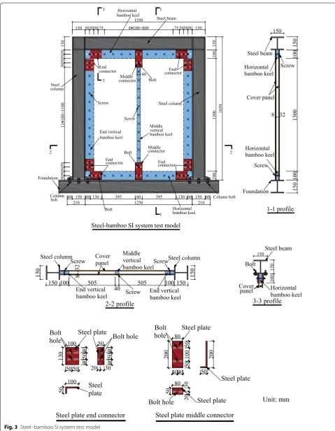
In this paper, the single-span one-story plane model of steel–bamboo SI system was investigated. Beams and columns of the steel frame are made of Q235-grade H-section steels, the elastic modulus of the steel is 2.1 × 10⁵ MPa and the yield strength is 235 MPa. The material used in the bamboo infilled wall is bamboo scrimber. The moisture content of the bamboo is about 9%, and the density is between 1.1 and 1.2 g/cm3. The bamboo infilled wall is made of horizontal bamboo keel, vertical bamboo keel and bamboo cover panel, which are connected by screws. The bamboo infilled
wall and the steel frame are bolted together by steel plate. The specific mechanical properties of bamboo scrimber, steel and screw are shown in Table 1. The specific specimen is shown in Fig. 3.
Steel frame (S)
The clear span of the steel frame is 1250 mm, and the height is 1650 mm. All beams and columns are HW150 × 150. The details of connections between beam and column and between column and foundation are shown in Fig. 4. The beam–column joint is referred to the Chinese code of constructional detail of multi-story and high-rise civil construction steel structure nodes 01SG519 [21]. The connection between column and beam is a steel plate which is welded on the column and bolted on the beam web, and the beam flange plate is also welded on the column. Six bolts are used to con-nect column and foundation in column base joint, and stiffener plate is welded on the column. All the bolts are 20 mm in diameter, and the strength grades of them are 8.8; the steel plates and stiffener plates are all 10-mm-thick Q235-grade steel plates.
Lateral load
Single-span one-story details
Connector details
Bolt Steel plate
Screw
Cover panel Bamboo keel
Fig. 2 Plane steel–bamboo model
Table 1 Mechanical properties of steel, bamboo and screw
Steel (Q235) Bamboo scrimber Screw
Elastic modulus
(MPa) Yield strength (MPa) Poisson ratio Elastic modulus (MPa) Shear modulus (MPa) Ultimate bending strength (kN) Initial stiffness (kN/mm)
Bolt
Column Column bolt
Horizontal bamboo keel 60 1550 13 00 Steel beam End
connector connectorEnd
Middle
connector Bolt
Horizontal
Bolt End
connector Endconnector
Middle connector Screw Screw End vertical bamboo keel Middle vertical bamboo keel Horizontal bamboo keel Horizontal bamboo keel Cover panel 1-1 profile 3 3
150 5050 7550 8 100=800 75
50 505050 150 50 50 11 100=110 0 50 50 50 50 50 15 0 15 0 10 0 100 165 0 60
150 130 395 80 395 130 60 150
1250 60 210 210 40 Steel beam Steel column bamboo keel 150 bolt Foundation 1 1 2 2 Screw 10 0 15 0 Foundation Screw 10 0 13 00
Steel-bamboo SI system test model
8 32
15
0
Steel column
Steel column Steel column
Steel beam
Bolt
Cover
panel Horizontalbamboo keel Cover panel Middle vertical bamboo keel End vertical bamboo keel End vertical bamboo keel
2-2 profile 3-3 profile
Screw Screw Screw 15 0 15 0
150 100 505
40 505 100 150
150 15 0 10 0 8 32 100 40 50 40 5050 130 50 40 50 40 20 30 100 50 80 50 10 0 50 20 0 20 0 50 80 30 20 50 4040
Steel plate end connector Steel plate middle connector
Steel plate
Bolt Bolt hole
hole Steel plate Steel plate Steel plate Steel plate Bolt hole
Bolt hole Unit: mm
Bamboo infilled wall (I)
The plane size of the bamboo infilled wall is 1250 mm × 1500 mm, and the thickness of the cover panel is 8 mm. The width of the horizontal bamboo keel and end-vertical bamboo keel is 100 mm, the width of the middle-vertical bamboo keel is 40 mm and both have thickness of 32 mm. The specific dimensions are shown in Table 2. The distribution of bolts and screws is shown
in Fig. 3. The connection between the keel and the cover panel is made of screws and bolts. Bolts with diameter of 12 mm are used at the joints and the spacing is 50 mm, and the others are connected by screws which have a diameter of 5 mm and a spacing of 100 mm.
Experimental device and loading method
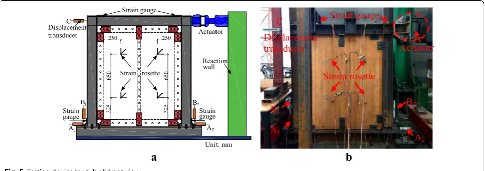
The test device diagram is shown in Fig. 5. The 100 t pseudo-static hydraulic servo actuator was used for the low-cycle reversed loading test. In this test, the bamboo infilled wall was connected to the steel beam foundation by bolts, and the steel beam foundation was anchored in the groove by ground anchor bolts. In order to prevent lateral instability of the specimens during loading, lateral braces were installed outside the plane of the steel beam. In order to analyze the properties of the steel–bamboo SI system, strain gauges were arranged at the column base and beam–column joints, and strain rosettes were arranged on the wall where the position avoids the stress concentration. Four displacement transducers were installed in the horizontal and vertical directions of the column bases to monitor the rigid body displacement, which are shown as A1, A2, B1, B2 in Fig. 5a. A displace-ment transducer was installed in the central line of steel beam away from the load end to measure the total lat-eral displacement, which is shown as C in Fig. 5a. The story displacement of the steel–bamboo SI system can be obtained by subtracting rigid body displacement from the total displacement. The strain and displacement were collected by DH3816N digital acquisition instrument.
In this test, a hybrid loading protocol of displacement control loading after force control loading is adopted. It can be divided into three stages: The first stage of load-ing is before the formal test and the pre-added force amplitude is 20 kN in order to check whether each 4
Column base rigid joint 4
4-4 profile
30
50
16
10
0
150
20
0
45
30
30
40
105 105
60 50
270 60 150 70
7
5-5 profile
30 40
30
hf
hf
Beam-column rigid joint 5 5
15
0
Steel column
Foundation Column bolt
Stiffener plate Steel Steel beam
Steel plate column Bolt
Column
bolt Steel column
Steel beam Bolt
Stiffener plate
hf
Unit: mm Fig. 4 Column base and beam–column connection
Table 2 Component dimensions
The l is length, the b is width and the t is thickness
Components Dimension l ×b ×t (mm)
Horizontal bamboo keel 1250 × 100 × 32 Middle-vertical bamboo keel 1500 × 40 × 32 End-vertical bamboo keel 1500 × 100 × 32 Cover panel 1500 × 1250 × 8
a
b
Strain gauge
Strain Strain rosette
Reaction Actuator Displacement
transducer
gauge Strain
gauge
250 250
32
5
65
0
32
5
65
0 wall
C
B1
A1 A2
B2
Unit: mm
Actuator Displacement
transducer
Strain gauge
Strain rosette C
B1
A1
B2
A2
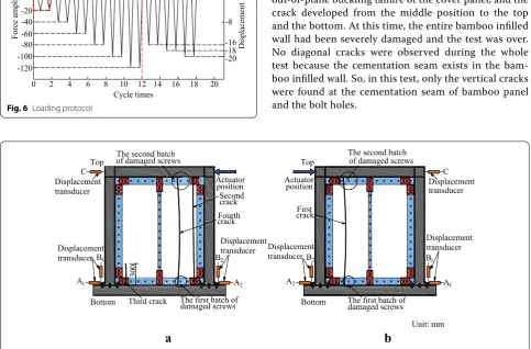
instrument and equipment work normally. The second stage is force control loading. Before the test, the lat-eral force was calculated to be 120 kN when the col-umn base yields, so the force control loading is adopted before the column base yields. The loading starts from 20 kN, increasing 20 kN in the next stage and twice cycles in each stage, until the loading becomes 120 kN. The third stage is displacement control loading, starting from 16 mm, increasing 2 mm at each level, and load-ing rate is 1.5 mm/min. The test loadload-ing protocol curve is shown in Fig. 6. The criteria of test termination are: (1) When the lateral load falls below 85% of the ulti-mate load or the member is destroyed, the load should be terminated; (2) if the lateral displacement and the inter-story displacement angles of the steel–bamboo SI system exceed the serviceability limit value, the load should be terminated.
Results and discussions
Experimental phenomena
As shown in Fig. 7, the main failure mode of steel– bamboo SI system in this test was the failure of the bamboo infilled wall, which could be divided into screw shear failure and cover panel failure. When the dis-placement was loaded to 20 mm by actuator, the first crack appeared at the cementation seam of the cover panel, and it developed at a length of 30 cm from top to bottom. When loaded to 22 mm, the first crack contin-ued to develop downward the middle position. When loaded to 24 mm, the second crack rapidly develops 115 cm from the top bolt hole. The existence of bolt hole weakens the strength of bamboo infilled wall, causing the crack to develop from here.
Then, when loaded to 28 mm, the third crack expanded upward about 30 cm from the bottom bolt hole, while the first batch of screws broke. When loaded to 32 mm, three cracks mentioned above con-tinued to develop and the second batch of screws broke. The loading path was broken so that lateral bear-ing capacity and lateral stiffness of the steel–bamboo SI system were reduced. When loaded to 36 mm, the first and second cracks expanded from top to bottom. At the same time, the fourth crack appeared due to the out-of-plane buckling failure of the cover panel, and the crack developed from the middle position to the top and the bottom. At this time, the entire bamboo infilled wall had been severely damaged and the test was over. No diagonal cracks were observed during the whole test because the cementation seam exists in the bam-boo infilled wall. So, in this test, only the vertical cracks were found at the cementation seam of bamboo panel and the bolt holes.
20 40 60 80 100 120
-20 -40 -60 -80 -100 -120
0 2 4 6 8 10 12 14 16
Forc
ea
mplitude
(kN)
Force control Displacement control
D
is
pla
ce
me
nta
m
pl
itu
de(
m
m)
Cycle times
Preloading 8
16
-8
-16 -18 18
18 20
-20
20
Fig. 6 Loading protocol
a
b
Second
Fourth The second batch
The first batch of crack
crack Actuator
position
damaged screws of damaged screws
Third crack
300
Displacement transducer Displacement
transducer
Displacement transducer
Actuator
The second batch
The first batch of
transducer position
damaged screws of damaged screws
Displacement transducer First
Top
crack
Displacement
Bottom Bottom
Displacement transducer
Top C
B1
A1 A2
B2
C
B2
A2
B1
A1
Unit: mm
Hysteretic behaviors
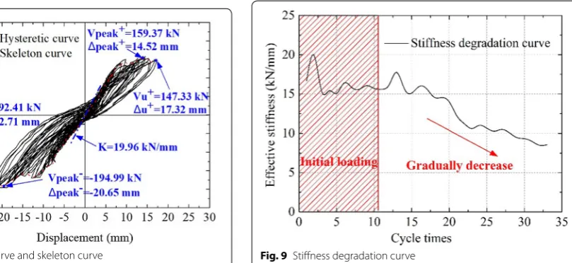
Figure 8 is the story load–story displacement hysteretic curve and skeleton curve of the steel–bamboo SI sys-tem test specimen. Because the slight rigid body rota-tion occurs during the test, the story displacement is obtained by the total lateral displacement measured by the displacement transducer C minus the rigid body displacement measured by the displacement trans-ducers A1, A2 and B1, B2 which is specifically equal to C−(A1−A2)/2−(B2−B1)/1600×1575. The hys-teretic curve presents a typical bow-shaped feature which indicates pinch phenomenon of hysteretic curve. The tension–compression zone of this hysteresis curve shows asymmetry characteristic, mainly because the steel–bamboo SI system and steel beam foundation, steel beam foundation and ground are all connected by bolts, and the gap between the bolts causes the bolts to slip, which results in the small measured positive displace-ment. In the initial stage, the load–displacement rela-tionship changes linearly which shows that the damage of the structure is small. And the lateral stiffness of the SI system does not change significantly. When the load is close to 120 kN, the column base of steel frame begins to yield and then becomes the displacement control load-ing. With the increasing displacement, the lateral stiff-ness decreases gradually due to the cracks of the bamboo infilled wall and the screws failure.
The skeleton curve can reflect the ultimate bearing capacity, deformability and stiffness characteristics of the structure. The peak load value and the limit failure load value in the positive and negative directions are shown in Fig. 8. Other mechanical properties are shown in Table 3. It can be seen from the skeleton curve that the slope of the load–displacement curve has no obvious change in the ± 10 mm displacement, which is approximately a
straight line, indicating that there is no significant change in the lateral stiffness. In the subsequent loading pro-cess, the bearing capacity of the system did not decrease significantly after the peak, indicating that most of the screws were not destroyed, and the structure still main-tains a high bearing capacity.
Stiffness analysis
In order to reflect the stiffness of structure under cyclic loading, secant stiffness is used to represent the effective stiffness of structure [22]. The effective stiffness of the ith cycle is defined in Eq. (1):
where P+i and Pi− are the positive and negative maximum
loads of the ith cycle, respectively, and Xi+ , Xi− are the displacements corresponding to the positive and negative maximum loads of the ith cycle, respectively.
The effective stiffness degradation curve of the steel– bamboo SI system is shown in Fig. 9. It can be clearly seen from the effective stiffness degradation curve that the stiffness does not reduce at the initial stage. After-ward, the lateral stiffness of the steel–bamboo SI system
(1) Ki=
P
+
i +
P
−
i
Xi+ +
Xi−
Fig. 8 Hysteretic curve and skeleton curve
Table 3 Mechanical properties of the steel–bamboo SI system
Performance
index Yield load (kN) Vy ∆y (mm) Initial stiffness K (kN/mm)
Ductility coefficient D
Steel–bamboo
SI system 153.58 11.48 19.96 1.75
gradually decreases due to the yield of the column base and the failure of the bamboo infilled wall.
Strength analysis
In order to indicate the strength degradation degree of the steel–bamboo SI system, the strength degradation coefficient specified in the Chinese code of specification for seismic test of buildings (JGJ/T 101-2015) [22] can be used. Because the mixed loading protocol is adopted in the low-cycle reversed loading test of the steel–bamboo SI system, at the force control loading stage, the strength degradation coefficient is defined as Eq. (2):
where the ij is the displacement of the peak point of the
ith cycle when the jth stage is loaded and ij−1 is the dis-placement of the peak point of the (i − 1)th cycle when the jth stage is loaded.
At the displacement control loading stage, the strength degradation coefficient is defined as Eq. (3):
where the Fji is the load of the peak point of the ith cycle when the jth stage is loaded and Fji−1 is the load of the peak point of the (i − 1)th cycle when the jth stage is loaded.
The steel–bamboo SI system strength degradation curve is shown in Fig. 10. It can be seen from the strength degradation curve that the strength degradation coef-ficient fluctuates greatly in the force control stage. In the subsequent loading stage, the strength degradation (2) =
ij
ij−1
(3) =
Fji
Fi−1 j
coefficient is stable at about 1.0, which indicates that the strength degradation phenomenon is not obvious.
Energy dissipation capacity
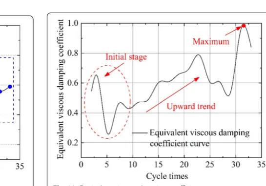
The energy dissipation capacity of the steel–bamboo SI system is also an important index to measure the seismic behavior. According to the Chinese code of specification for seismic test of buildings (JGJ/T 101-2015) [22], the structural energy dissipation capacity can be measured by the equivalent viscous damping coefficient ζeq . The equivalent viscous damping coefficient can be calculated by Eq. (4):
where ED is the area of the hysteretic loop (ABC + CDA) and EP is the sum of the area of the triangle OBE and the triangle ODF in Fig. 11.
The relationship between the equivalent viscous damp-ing coefficient and the cycle times of the steel–bamboo SI system can be obtained as shown in Fig. 12. It can be seen from the curve that the variability of the equivalent (4) ξeq=
1 2π ·
ED
EP
Fig. 10 Strength degradation curve
Force
A
F E
C Displacement B
D
O Hysteretic loop
Fig. 11 Diagram of equivalent viscous damping coefficient calculation
viscous damping coefficient is large at the initial stage. With the increase in cycle times, the energy dissipa-tion capacity of the system shows an upward trend. The equivalent viscous damping coefficient can reach almost 1.0, which indicates that energy dissipation capacity of the steel–bamboo SI system is good. Then, the energy dissipation capacity begins to decrease after the system is destroyed.
Theoretical analysis of steel–bamboo SI system
Theoretical analysis
In the steel–bamboo SI system, the stability of the steel frame is enhanced because the bamboo infilled wall acts as diagonal bracing. Because the low cyclic loading is used in this test, the infilled wall is needed in order to play a supporting role in both push and pull directions, so the equivalent cross bracing is more reasonable. Based on the above principle, the lateral stiffness formula of the structure is summarized through theoretical analysis, and the axial stiffness and ultimate bearing capacity of the diagonal bracings are derived.
Lateral stiffness formula
The lateral deformation of the bamboo infilled wall con-sists of three parts: lateral deformation of the screws on the horizontal keels and the vertical keels, shear defor-mation of the bamboo infilled wall and bending deforma-tion of the bamboo infilled wall. In order to obtain the formula of lateral stiffness, the following hypotheses are made for bamboo infilled wall:
1. The horizontal internal force components of hori-zontal keel will be uniformly distributed along the keel, and the vertical internal force components of vertical keel will be uniformly distributed along the keel.
2. The influence of vertical internal force component of the horizontal keel and horizontal internal force component of the vertical keel on bamboo infilled wall’s shear deformation is ignored;
3. The shear stress of the bamboo infilled wall is uni-formly distributed in the effective force range; 4. The initial stiffness and bearing capacity of the screws
are equal in all directions;
5. The vertical deformation of screws of horizontal bamboo keels is neglected, and the lateral deforma-tion of screws of vertical bamboo keels is neglected.
Thus, the overall deformation formula of the wall is Eq. (5):
(5) Z=b+M+Q
where Z is the total deformation of bamboo infilled
wall; b is the lateral deformation of the bamboo infilled wall caused by the screws; M is the bending deforma-tion; and Q is the shear deformation.
The total deformation of the bamboo infilled wall can be given in Eq. (6):
where FZ is the lateral force shared by bamboo infilled wall and KZ is the lateral stiffness of bamboo infilled wall.
The bolts in this test have high strength and the lateral displacement of the bolts is extremely small, so only screws are considered in this paper. The deformation of screws is divided into two parts: the lateral deformation of screws of the horizontal keels and the vertical deformation of screws of the vertical keels. Respective screws have different defor-mations by bending deformation of bamboo wall, but in this paper the average deformation value is used to sim-plify the formula. So, the lateral deformation of the bam-boo infilled wall caused by the screws can be expressed as Eq. (7):
where nb is the number of screws on the horizontal keels; nh is the number of the screws on the vertical keel; and Kb is the stiffness of twin shear screw node.
The shear deformation of bamboo infilled wall is shown in Eq. (8):
where GZ is the transverse shear modulus of the wall; t is
the thickness of the wall; bw is the effective width of the wall which is surrounded by screws; and hw is the effec-tive height of the wall which is surrounded by screws.
The inflection point of the wall is located at the center section; thus, the bending deformation of the bamboo infilled wall can be regarded as the sum of the upper and lower part deformations. Each part is assumed to be a can-tilever, and the deformation can be given in Eq. (9):
where EZ is the bending elastic modulus of the wall and
Iw is the effective section moment of inertia.
To summarize, lateral stiffness of bamboo infilled wall can be expressed as Eq. (10):
(6) Z=
FZ
KZ
(7) b= 2FZ
nbKb
+2·FZ ·hwbw
nhKb
·bw hw
=2FZ Kb
· 1
nb
+ 1 nh
(8) Q= FZ
GZtbw
·hw
(9) �M=2·FZ·(hw
2)3 3EZIW
= FZh
3 w
12EZ·tb 3 w 12
= FZh
The lateral stiffness of steel frames Ks is Eq. (11):
where Es is the elastic modulus of the steel column; Is is the moment of inertia of the steel columns; and hG is the story height of the steel frame.
Thus, the overall lateral stiffness of the steel–bamboo SI system can be given in Eq. (12):
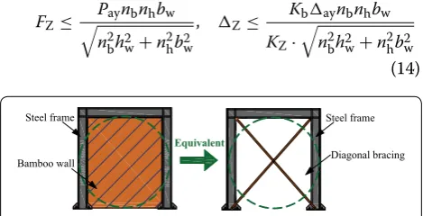
Equivalent diagonal bracing formula
The equivalent bracing of bamboo infilled wall is shown in Fig. 13, and the stability of diagonal braces is ignored. There are two main factors limiting the bearing capacity of bamboo infilled wall: one is the bearing capacity of screws, and another is the strength of bamboo infilled wall. It can be observed from the low-cycle reversed loading test that the bamboo wall is not damaged when the screws reach the yield load. Therefore, the yield load of the screws should be taken as the design load capacity (i.e., the 50% of the ulti-mate load of the screw). It is written in Eq. (13):
where Pa is the internal forces for screws and partial safety can be taken as Pa=
Pah2 +P2
av , in which, Pah=FZ/nb is the average internal force of the screws on the horizontal bamboo keel, Pav=FZhw/nhbw is the average internal force of the screws on the vertical bam-boo keel; Pay is the yield bearing capacity for screws; a is the corresponding deformation of Pa ; and ay is the cor-responding deformation of Pay.
The parameters in Eq. (13) are brought to get the allow-able bearing capacity and deformation of the bamboo infilled wall. It can be shown in Eq. (14):
(10)
KZ= 1
2
nbKb+ nhKb2 + hw GZtbw +
h3 w EZtb3
w
(11) KS=
24ESIS
h3G
(12) KZ=
1
2 nbKb+
2 nhKb+
hw
GZtbw +
h3 w
EZtb3w
+ 24ESIS
h3G
(13)
Pa≤Pay, a≤ay
(14) FZ≤
Paynbnhbw
n2bh2
w+n2hb2w
, Z≤
Kbaynbnhbw
KZ·
n2bh2
w+n2hb2w
The overall deformation of the steel frame–bamboo infilled wall can be expressed in Eq. (15):
The height of the steel frame is hG , the span of the steel frame is bG , the length of the equivalent diagonal bracing is L and the angle between the bracing and the horizontal direction is θ. According to the geometric relationship, there is:
Using L as a function of bG and deriving from bG , Eq. (17) can be obtained.
Then,
Therefore, the ′
z can be expressed by the axial defor-mation of the bracing as Eq. (19):
where ExAx is the axial stiffness of the equivalent diago-nal bracing.
Equations (6), (15) and (19) can be used to obtain the expression of axial stiffness of equivalent diagonal bracing:
The axial force of each diagonal bracing should satisfy Eq. (21):
The formulas mentioned above are mainly aimed at structural design, and no specific study has been made on the overall yield of the system. Therefore, only the equiva-lence of the system in the linear elastic stage is emphasized.
Comparison of theory and experiment
In order to verify the correctness of the simplified for-mula, the elastic lateral stiffness obtained by theoretical calculation is compared with the elastic stiffness obtained (15) ′
Z=Z+ h
3 G
24ESIS
(16) L=
b2G+h2G
(17) dL=dbG·
bG
L =dbG·cosθ
(18) dL=�′
z·cosθ
(19) �′Z= FZ(b
2 G+h2G)
3 2
2ExAxb2G
(20) ExAx= 12ESISFZ·(b
2 G+h2G)
3 2
b3Gh3G+24b2G�ZESIS
(21) Fx≤
1 2 ·
b2G+h2G
bG
·Paynbnhbw n2bh2
w+n2hb2w
Steel frame
Bamboo wall
Steel frame
Diagonal bracing Equivalent
by the experiment. The material properties of bamboo scrimber and screws are referred from Table 1.
The elastic stiffness obtained from the experiment is K′=19.96 kN/mm as shown in Table 2. And according to Eq. (12), the elastic stiffness is calculated as follows:
Comparing the test results with the theoretical calcu-lation results, the theoretical calcucalcu-lation value is greater than the test value, and the relative error between the two is about 1.3%. The main reasons for this result are: In the actual test, the internal forces of screws and infilled walls are not uniform; the stress concentration phenomenon occurred in the screw joint; the actual bamboo infilled walls are anisotropic materials; and the mechanical prop-erties of the transverse and longitudinal walls are quite different. However, these factors have little effect on the lateral displacement of bamboo infilled wall, and the test value is in good agreement with the theoretical calcula-tion value. Based on the above consideracalcula-tions, the lateral stiffness formula proposed in this paper can be basically used to calculate the lateral stiffness of infilled walls.
Conclusions
In the present study, a new steel–bamboo SI system was proposed. In order to investigate the seismic perfor-mance of the proposed system, a simplified plane steel frame–bamboo infilled wall structure was tested consid-ering the geometrical symmetry of the SI system and test conditions. The main results are summarized as follows:
1. The main failure modes of steel–bamboo SI system under low-cycle reversed loading are the failure of screws and cover panels, and the bolts are not damaged. 2. The strength degradation of the steel–bamboo SI
system is slow, and it still maintains good bearing capacity in this test. The peak load in the positive direction is 159.37 kN and in the negative direction is − 194.99 kN. The initial stiffness is 19.96 kN/m. The energy dissipation capacity of the steel–bamboo SI system is good, and the energy dissipation capacity shows a rising trend.
3. The formula for calculating the lateral stiffness of the steel–bamboo SI system is summarized. The error between the test results and the theoretical results is about 1.3%. It is proved that the formula can be used for calculating the lateral stiffness basically.
KZ= 1
2 nbKb+
2 nhKb+
hw GZtbw +
h3 w EZtb3
w
+24 ESIS
h3G =20.23 [kN/mm]
Abbreviations
SI: skeleton–infill; FRP: fiber-reinforced polymer; SAR: Stichting Architecten Research; CSI: China skeleton infill.
Acknowledgements
The authors would like to extend their sincere gratitude for the financial sup-port from the Integrated Key Precast Components and New Wood-bamboo Composite Structure Foundation of China (2017YFC0703502) and for the test work provided by the Jiangsu Transportation Institute Structural Laboratory.
Authors’ contributions
QL designed the test plan, led the whole test and analyzed the test data. YD deduced the theoretical formula and is also the main author of the manu-script. YL revised the manuscript and is the main corresponding author. All authors read and approved the final manuscript.
Funding
The whole test study is supported by the Integrated Key Precast Components and New Wood-bamboo Composite Structure (2017YFC0703502).
Availability of data and materials
The datasets generated and analyzed during the current study are not publicly available due to the fund which supporting this test do not agree to make the data public, but are available from the corresponding author on reasonable request.
Competing interests
The authors declare that they have no competing interests.
Received: 5 December 2018 Accepted: 26 September 2019
References
1. Xu Q, Chen L, Harries KA, Li X (2017) Combustion performance of engi-neered bamboo from cone calorimeter tests. Eur J Wood Wood Prod 75:161–173. https ://doi.org/10.1007/s0010 7-016-1074-6
2. Sharma B, Gatóo A, Bock M, Ramage M (2015) Engineered bamboo for structural applications. Constr Build Mater 81:66–73. https ://doi. org/10.1016/j.conbu ildma t.2015.01.077
3. Sharma B, Gatóo A, Bock M, Mulligan H, Ramage M (2014) Engineered bamboo: state of the art. Proc Inst Civ Eng Constr Mater 168:57–67. https ://doi.org/10.1680/coma.14.00020
4. Brown JL (2004) Bamboo house passes seismic test. Civ Eng 74:27 5. Lv Q, Wei Y, Zhang Q, Yu Y, Lv Z (2008) Key technologies of the
new anti-seismic model living room with bamboo engineer-ing materials. Spec Struct 25:6–10. https ://doi.org/10.3969/j. issn.1001-3598.2008.04.002
6. Xiao Y, Zhou Q, Shan B (2010) Design and construction of modern bam-boo bridges. J Bridge Eng 15:533–541. https ://doi.org/10.1061/(ASCE) BE.1943-5592.00000 89
7. Li S, Fu S, Zhou B, Zeng Q, Bao X (1994) Reformed bamboo and reformed bamboo aluminium composite Part I manufacturing technique, structure and static properties. J Mater Sci 29:5990–5996. https ://doi.org/10.1007/ BF003 66884
8. Wei Y, Wu G, Li G, Zhang Q, Jiang S (2014) Mechanical behavior of novel FRP-bamboo-concrete composite beams. J Cent South Univ 45:4384–4392
9. Wei Y, Ji X, Duan M, Li G (2017) Flexural performance of bamboo scrimber beams strengthened with fiber-reinforced polymer. Constr Build Mater 142:66–82. https ://doi.org/10.1016/j.conbu ildma t.2017.03.054 10. Zhong Y, Wu G, Ren H, Jiang Z (2017) Bending properties evaluation
of newly designed reinforced bamboo scrimber composite beams. Constr Build Mater 143:61–70. https ://doi.org/10.1016/j.conbu ildma t.2017.03.052
12. Li Y, Shan W, Shen H, Zhang Z, Liu J (2015) Bending resistance of I-section bamboo–steel composite beams utilizing adhesive bonding. Thin-Walled Struct 89:17–24. https ://doi.org/10.1016/j.tws.2014.12.007
13. Gao WC, Xiao Y (2017) Seismic behavior of cold-formed steel frame shear walls sheathed with ply-bamboo panels. J Constr Steel Res 132:217–229. https ://doi.org/10.1016/j.jcsr.2017.01.020
14. Habraken NJ (1972) Supports: an alternative to mass housing. Praeger Publishers, New York
15. Kendall S (2017) Four decades of open building implementation: realising individual agency in architectural infrastructures designed to last. Archit Des 87:54–63. https ://doi.org/10.1002/ad.2216
16. Cao X, Li Z, Liu S (2015) Study on factors that inhibit the promotion of SI housing system in China. Energy Build 88:384–394. https ://doi. org/10.1016/j.enbui ld.2014.11.064
17. Ji Y, Huang W, Zhang T (2009) Research on the environmental sustainable development of industrial skeleton–infill houses. Paper presented at the fourth international conference on computer sciences and convergence information technology, IEEE Computer Society, Seoul, 24–26 November 2009
18. Flander KD, Rovers R (2009) One laminated bamboo-frame house per hectare per year. Constr Build Mater 23:210–218. https ://doi. org/10.1016/j.conbu ildma t.2008.01.004
19. Ribeiro RAS, Ribeiro MGS, Miranda IPA (2017) Bending strength and nondestructive evaluation of structural bamboo. Constr Build Mater 146:38–42. https ://doi.org/10.1016/j.conbu ildma t.2017.04.074 20. Van der Lugt P, Van den Dobbelsteen A, Janssen JJA (2006) An
environ-mental, economic and practical assessment of bamboo as a building material for supporting structures. Constr Build Mater 20:648–656. https ://doi.org/10.1016/j.conbu ildma t.2005.02.023
21. China Institute of Building Standard Design and Research (2004) Multi-story and high-rise steel structure connection drawings: 01SG519. China Planning press, Beijing
22. Ministry of Housing and Urban-Rural Development of the People’s Republic of China (2015) Specification for seismic test of buildings: JGJ/T 101-2015. China Architecture & Building Press, Beijing
Publisher’s Note
![Fig. 1 Draft for a a traditional steel–bamboo composite structure [13] and b the steel–bamboo SI system](https://thumb-us.123doks.com/thumbv2/123dok_us/901592.1587762/2.595.58.542.535.710/draft-traditional-steel-bamboo-composite-structure-steel-bamboo.webp)