IJEDR1803042
International Journal of Engineering Development and Research (www.ijedr.org)
231
Strengthening of Beams Using Glass Fiber
Reinforced Polymer (GFRP) Laminate
1Sameer Shrivastava,2A. Tiwari
1PG Scholar, Dept of Civil Engineering, Madhav Institute of Technology & Science, Madhya Pradesh, India 2Professor &Head, Dept of Civil Engineering, Madhav Institute of Technology & Science, Madhya Pradesh, India _____________________________________________________________________________________________________ Abstract—Several existing reinforced concrete structures all over the entire world are in critical need of repair and rehabilitation because of deterioration due to various factors like venerable, improper maintenance, corrosion of steel reinforcement, marginal design, poor construction, use of inferior material, design demands due to increased service loads, exposure to harmful environments and damage in case of seismic events like earthquakes and improvement in design guidelines. The latest developments in the use of the superior composites in the construction industry for concrete structures in strengthening and rehabilitation are growing on the basis of requirements. The requirement for efficient strengthening and rehabilitation techniques of existing structures has resulted in the research and development of composite strengthening systems. Fiber- reinforced polymer (FRP) Composite application is an extremely efficient method in repairing and strengthening of structures which has become structurally weak over their life span. FRP composites systems of strengthening provide an economically viable substitute to conventional repair systems and materials. In the present study experimental investigation is carried out to study the flexural and shear behavior of Reinforced Concrete (RC) beams by using Glass Fiber Reinforced polymer laminate. Beams were strengthened with 1.2 mm Epoxy Bonded Glass Fiber Reinforced Polymer ((GFRP)) lamination using epoxy resins and tested to fail using a symmetrical two-point loading system. Strengthening of beam is done with different combinations of (GFRP) laminate. Total 9 beams of size 150 mm X 150 mm X 1000mm were casted initially out of which 3 beams were controlled beams and the rest 6 beams were strengthened with different combinations of (GFRP) laminate such as U-wrap, Bottom Wrap and Side U-wrap. The corresponding load and the corresponding deflection for each beams were recorded and the load deflection behavior of each beam was compared with that of their respective control beams.
IndexTerms—(GFRP), Epoxy material, Strengthening, rehabilitation.
_____________________________________________________________________________________________________
I.INTRODUCTION
There are many existing concrete structures such as buildings, bridge decks, girders and offshore structures deteriorated just because of venerable, improper maintenance, corrosion of steel reinforcement, marginal design, poor construction, use of inferior material, design demands in the increased service loads, exposure to harmful environments and damage in case of seismic events like earthquakes and improvement in design guidelines. These deteriorated structures are unable withstand the load for which they were designed. Therefore maintenance, rehabilitation and up gradation of structures is one of the most crucial problems in civil engineering areas. Thus, such kinds of structures either need complete replacement or strengthening. Instead of replacement of structures, the most reliable solution is to dismantle the structure completely and following with strengthening of affected structures which may increase the load carrying capacity of the structure as well as the durability of the structure.
Structural strengthening involves enhancing the ability of structural elements to safely resist the internal forces caused by loading such as flexure, shear, axial and torsion. Some strengthening techniques such as enlargement of sections, externally bonded reinforcement, post-tensioning and additional support may be used to achieve enhanced strength and serviceability.
Carbon Fiber Reinforce Polymer (CFRP), Glass Fiber Reinforce Polymer (GFRP) and Armid Fiber Reinforce Polymer (AFRP) sheets, laminate, bars are commonly used as strengthening materials due to their light weight, high strength and excellent corrosion resistant capability
II.LITERATUREREVIEW
1. N. Pannirselvam. (2008), presented a study to evaluate the structural behavior of reinforced beams with externally bonded FRP reinforcements. Total fifteen beams specimen having three different steel ratios, wrap thickness and wrap material were tested. The Variables in study were longitudinal steel ratio, types of Glass Fiber Reinforce Polymer (GFRP) laminate, thickness of Glass Fiber Reinforce Polymer (GFRP) laminates and composite ratios. A two-point loading system was adopted for testing. Authors found 28.57% to 40% increment of ultimate load for 3 mm thick Glass Fiber Reinforce Polymer (GFRP) sheet and 28.57% to 128.57% increment of ultimate load for 5 mm thick Glass Fiber Reinforce Polymer (GFRP) sheet.
IJEDR1803042
International Journal of Engineering Development and Research (www.ijedr.org)
232
effectiveness of different schemes were evaluated. It was observed that tension side bonding of Carbon Fiber-Reinforced Polymer (CFRP) sheets with U-shaped end.3. Sherif H. Al-Tersawy. (2013), examined the performance of reinforced concrete (RC) beams strengthened in shear. Experimental investigation was carried out on nine RC beams of three different sets, as-built beams (unstrengthen), beams strengthened with vertical Carbon Fiber-Reinforced Polymer (CFRP) wraps, and beams strengthened with inclined Carbon Fiber-Reinforced Polymer (CFRP) wraps. The main parameters investigated were concrete strength, Carbon Fiber-Reinforced Polymer (CFRP) thickness and wraps orientations (900 & 450). The results of the experimental work indicated that externally bonded CFRP wraps enhanced the shear strength of beams significantly and that inclined Carbon Fiber-Reinforced Polymer (CFRP) configuration is more effective than vertical ones. 4. Firmo J et al, (2015) This paper presents experimental and numerical investigations about the fire resistance behavior
of Reinforced Concrete (RC) beams flexurally strengthened with Carbon Fiber Reinforced Polymer (CFRP) laminates. The main objective was to assess the efficacy of different fire protection systems and to evaluate the viability of their use in floors of buildings. Result shows that when the strengthening system was left unprotected in the exposed length of the beam, the Carbon Fiber-Reinforced Polymer (CFRP) laminate anchorage deboned after about 23 min. When fire protection materials were applied in the exposed length of the beams, the strengthening system deboned after between 60–89 min (25 mm thickness) and 137-167 min (40 mm). Results demonstrated the efficacy of the retrofitting systems in its ability to retain the structural integrity via a cable mechanism although the debonding of Carbon Fiber-Reinforced Polymer (CFRP) strip in the beams had occurred and also the fire resistance of the Carbon Fiber-Reinforced Polymer (CFRP) was extended to 70 minutes
III.OBJECTIVE OF WORK
• To calculate the effectiveness of the external Glass Fiber-Reinforced Polymer (GFRP) wrapping technique in Strengthening of Reinforced Concrete (RC) Beam.
• To study the ultimate load carrying capacity of the specimens in strengthening by Glass Fiber-Reinforced Polymer (GFRP) wrapping technique.
• To Measure the efficiency of the Glass Fiber-Reinforced Polymer (GFRP) fabrics in terms of utilization of the strength and deformation capacity of the FRP material.
• Evaluation of the results obtained from the Un-strengthen RC beam and Strengthen RC beams with different combinations of wrapped Glass Fiber-Reinforced Polymer (GFRP).
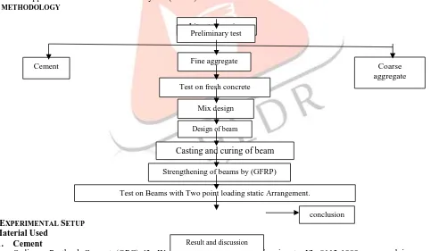
IV.METHODOLOGY
V.EXPERIMENTAL SETUP
A.Material Used 1. Cement
Ordinary Portland Cement (OPC)-43, Wonder Cement Grade conforming to IS: 8112-1989 was used in current experimental work. It was tested for physical properties in accordance with Indian Standard Specifications. The test Properties of ordinary Portland cement are given in Table 1.
Table 1 Properties of Cement
S.No Description of test Results obtained Requirement of IS: 8112-1989
1 Initial Setting Time 153 minutes Min. 30 minutes
2 Final Setting Time 243 minutes Max.600 minutes
3 Specific Gravity 3.125 3.15
2. Coarse Aggregate
Cement Coarse
aggregate Literature review
Preliminary test
Fine aggregate
Test on fresh concrete
Mix design
Design of beam
Casting and curing of beam Strengthening of beams by (GFRP)
Test on Beams with Two point loading static Arrangement.
Result and discussion
IJEDR1803042
International Journal of Engineering Development and Research (www.ijedr.org)
233
Coarse aggregates collected from approved quarry and aggregates having size ranging from 10mm to 20mm and specific gravity of coarse aggregate 2.87. The tests are carried out on coarse aggregate as per IS 2386-1963.3. Fine Aggregate
River sand passing through 4.75mm sieve is used and it has a specific gravity of 2.66. The grading zone of fine aggregate is Zone II. Physical properties of fine aggregates determined per IS 383-1970.
4. Water
The water is available in the college campus conforming to requirements of water for concreting and curing as per IS:456-2000.
5. Glass Fiber Reinforced Polymer (GFRP)
The uni-directional Glass Fiber Reinforced Polymer (GFRP) laminates of thickness 1.2 mm was used for strengthening of RC beams shown in Figure (a). the adhesives were used to ensure bond quality between concrete and layers. The properties of Glass Fiber Reinforced Polymer (GFRP) laminates supplied by manufacturer from Pondicherry Muthiraapalayam, Tamilnadu, India.
Fig: (a) (GFRP) Laminate of thickness 1.2 mm for strengthening of beams 6. Epoxy Resin
Epoxy resins is basically of low molecular weight pre-polymers capable of being processed under different conditions. It is a thermosetting polymer formed from reaction of an epoxy "resins" with polyamine " hardener ".
7. Reinforcement
The longitudinal reinforcements used were HYSD bars Fe 415 of 10 mm diameter and 8 mm diameter bars were used as hanger bars. The stirrups were made from Fe 250 mild steel bars of 6 mm diameter.
8. Mix proportion of concrete
Mix proportioning of M 30 grade of concrete has been carried out as per the Indian Standard 10262:1982 & Indian Standard 10262:2009. Based on the outcomes of constituents, mix design of concrete was carried out. Water cement ratio adopted for mix design was 0.45. Mix proportion for M30 concrete used for the current study is shown in Table 2.
Table 2 Mix proportion of M30 Concrete
Content Quantity
Cement 406.9kg/m3
Water 175 kg/m3
Fine aggregate 618.716 kg/m3
Coarse aggregate
1151.7 kg/m3
20 mm
692.12 kg/m3 10
mm
459.6 kg/m3
w/c ratio 0.43
9. Casting of Cubes
For cube compression testing of concrete, 150mmx150mmx150mm size cubes were used. The cubes were tested at the7 days and 28 days of curing by using compression testing machine
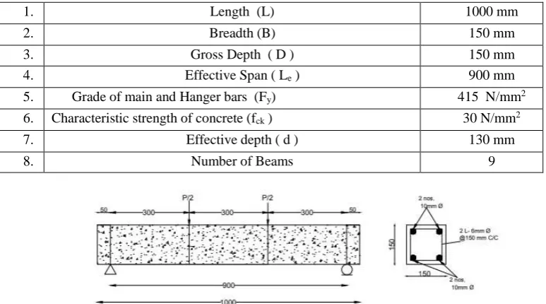
10. Design of Beams
The design details of beams shown in Table 3 as :
IJEDR1803042
International Journal of Engineering Development and Research (www.ijedr.org)
234
1. Length (L) 1000 mm
2. Breadth (B) 150 mm
3. Gross Depth ( D ) 150 mm
4. Effective Span ( Le ) 900 mm
5. Grade of main and Hanger bars (Fy) 415 N/mm2
6. Characteristic strength of concrete (fck ) 30 N/mm2
7. Effective depth ( d ) 130 mm
8. Number of Beams 9
Fig (b): Loading Diagram and Reinforcement detailing of the beam
11. Casting of Beams
All Nine beams were designed by limit state method considering the section to be under reinforced according to IS: 456-2000 code. Moulds of 150 x 150 x 100 mm size were prepared by using plywood. Concrete of M30 grade was designed as per IS10262 -1982, the mix proportion is 1:1.15:2.83 ratio (cement, sand and coarse aggregate), and the concrete was machine mixed. Following steps were adopted for casting of beams as follows:
1. First the entire mould was oiled. So that the beams can be easily de-moulded from the mould after 24 hours. 2. Cover blocks of size 20mm are used to provide uniform cover to the reinforcement, when the bars have been placed
in position.
3. Concrete mix was poured in layers and compacted using tamping rods & vibrator, the compaction is done until the mould is completely filled and carried out the process with nil voids.
4. The beams were then removed from the mould after 24 hours. Then the beams were cured for28 days.
5. Total 9 beam were casted out of which 3 were controlled beams and rest 6 beams were wrapped with Glass Fiber Reinforced Polymer (GFRP) laminate.
Fig (c): Beams After Casting 12. Strengthening of Beams
IJEDR1803042
International Journal of Engineering Development and Research (www.ijedr.org)
235
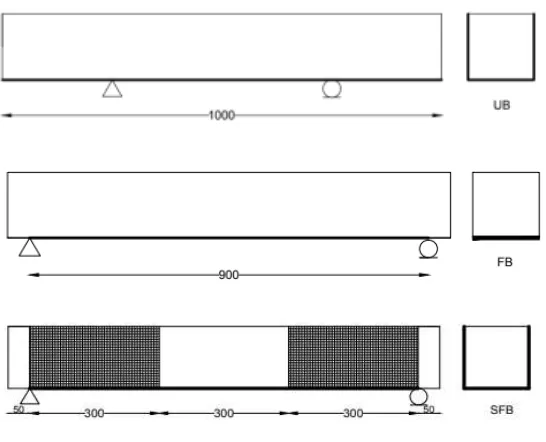
Fig (D): Beams After Casting1. The strengthen beam designated UB (U - wrapped Beam) that is strengthened in both shear and flexure. In this case Glass Fiber Reinforced Polymer (GFRP) Wrapping was provided on two shear sides and on the bottom flexure sides throughout the length.
2. The strengthen beam designated FB (Flexure wrapped Beam) was strengthened in flexure only. In this case wrapping was provided only on the soffit of beam over entire effective span of 900 mm of the specimen.
3. The strengthen beam designated SFB (U - wrapped Beam in Shear zone) was strengthen only at sides of beam in shear zone. Glass Fiber Reinforced Polymer (GFRP) wrapping provided on 3 sides of beam was placed over a distance of 300 mm from both supports.
B.Test Programme on Beams
Beams were strengthened with 1.2 mm Epoxy Bonded Glass Fiber Reinforced Polymer (GFRP) laminate using epoxy resins and tested to failure using a symmetrical two-point loading system on Universal Testing Machine (UTM). Tests on control beam was performed for determining the ultimate load and deflection. Later, obtained values are compared with the values of ultimate load and deflection obtained after testing of strengthened beams.
Fig-(E) Loading setup
VI.RESULT AND FINDINGS
A.Compressive Strength of Cubes
The compressive strength of cubes for 7-day strength shown in table
Table 4 Compressive Strength of Cube after 7days
S.NO SPECIMEN NO. COMPRESSIVE
STRENGTH
1. C 1 44.43Mpa
2. C 2 42.2Mpa
3. C 3 44.43Mpa
IJEDR1803042
International Journal of Engineering Development and Research (www.ijedr.org)
236
Graph 1 : Compressive Strength of Cube at 7 daysThe compressive strength of cubes for 28-day strength shown in table
Table 5 Compressive Strength of Cube after28 days S.NO SPECIMEN
NO.
COMPRESSIVE STRENGTH
1. C 1 53.33 Mpa
2. C 2 48.8 Mpa
3. C 3 53.33 Mpa
Compressive Strength of Cube on 28 days = 51.82 Mpa
Graph 2: Compressive Strength of Cube at 28 days
B.Load Deflection Behavior
The load deflection observations of all the beams was recorded. The load deflection behavior of each beam was compared with that of their respective control beams. Also compared between wrapping schemes having the same reinforcement. The graphs comparing the variations as shown below:
1. Yield load: The load at initial crack of all the beams was observed, recorded and is shown in Graph 9. In beam CB 1 & CB 2, initiation of the crack takes place at a load of 30 KN. In SFB 1 & SFB 2 beam initiation of the crack takes place at a load of 35 KN. In FB 1 & FB 2 Beam the crack initiation was takes place at a load of 45 KN., and UB 1 & UB 2 initiation of the crack takes place at a load of 55 KN.
0 10 20 30 40 50 60
C1 C2 C3
7 DAYS 44.43 42.2 44.43
CO M P RE SS IV E STT RE NGTH M p a
Compressive strength of cubes at 7 days
7 DAYS 0 10 20 30 40 50 60
C1 C2 C3
28 DAYS 53.33 48.8 53.33
C
OM
PRE
SS
IV
E
ST
RE
N
G
TH
(N
/m
m
2)
Compressive Strength of cubes
at 28 DAYS
IJEDR1803042
International Journal of Engineering Development and Research (www.ijedr.org)
237
Graph 4: Yield load Comparison among all Beams.2. Ultimate Load Carrying Capacity: The load carrying capacity of the control beams and the strengthen beams were found out and is shown in Graph 4.
Graph 4: Ultimate load Comparison among all Beams.
3. Ultimate load v/s Deflection Comparison
The comparison of beams among all beams between load deflection as shown in Graph 5 below. Beam tested for strengthening it was observed that both samples of strengthened beam SFB, FB and UB, when compared to unstrengthen beam, the strength was increased by 12.81%, 22.18% and 40.30% and deflection of beam are minimized due to U Wrapping technique of Glass Fiber Reinforced Polymer (GFRP) laminate.
Beam Sample 1 Beam sample 2
0 10 20 30 40 50 60 CONTROL BEAM (CB) U WRAPP IN SHEAR ZONE(SFB) BOTTOM WRAPPING (FB) U WRAPPING (UB)
Beam Sample 1 30 35 45 55
Beam sample 2 30 35 45 55
YI
ELD
LO
A
D
(KN)
YIELD LOAD COMPARISON
Beam Sample 1 Beam sample 2
0 20 40 60 80 100 CONTROL BEAM (CB) U WRAPP IN SHEAR ZONE(SFB) BOTTOM WRAPPIN G (FB) U WRAPPIN G (UB)
Beam Sample 1 56.09 67.8 70.63 81.25
Beam sample 2 61.22 64.53 72.7 83.33
UL
TI
M
A
TE
LO
A
D
in
K
N
IJEDR1803042
International Journal of Engineering Development and Research (www.ijedr.org)
238
Graph 5: load Deflection ComparisonVII.CONCLUSION
Total nine beams were tested out of which three beams were controlled beams and the rest of the beams were strengthened by using Glass Fiber Reinforced Polymer (GFRP) laminate with different combinations. Tests on control beam were conducted for ultimate load and deflection and compared with the values of ultimate load and deflection obtained after testing of strengthened beams. With the help of the obtained experimental test result and the calculated strength values, the following conclusions are drawn:
1. The yield load and cracks in Strengthened beam observe at higher load compared to Controlled beams.
2. The deflection of beam is minimized due to U Wrapping technique of Glass Fiber Reinforced Polymer (GFRP) laminate on the beam in comparison to control beam.
3. Beams tested for strengthening, it was observed that strengthened beam i.e. U - wrapped Beam in Shear Zone (SFB), Flexural Wrapped Beam (FB) and U - Wrapped (UB), when compared to unstrengthen beam, the strength was increased by 12.81%, 22.18% and 40.30%.
4. The increase in ultimate load carrying capacity of U - wrapped Beam in Shear Zone (SFB) beams is least in comparison to Flexural Wrapped Beam (FB) and U - Wrapped (UB) beams i.e. 9.37% and 27.49%.
5. The increase in ultimate load carrying capacity of Flexural Wrapped Beam (FB) beam is least in comparison to UB beam i.e 18.12%.
6. From the above research it is concluded that the strength is enhanced in the beam corresponding to the load by 13 % via providing Glass Fiber Reinforced Polymer (GFRP) with U wrap in shear zone (SFB) and to increase the strength by 23% strengthen the beam by providing Glass Fiber Reinforced Polymer (GFRP) at the soffit of beam similarly to achieve 41% strength the beam is strengthen by U wrap (UB) over the entire span of the beam.
REFRENCES
[1] Sherif H. Al-Tersawy.,” Effect of fiber parameters and concrete strength on shear behavior of strengthened RC beams”, Construction and Building Materials 44, pp.15–24, 2013.
[2] N. Pannirselvam., V. Nagaradjane, K. Chandramouli.,” Strength behavior of fiber reinforced polymer strengthened beam” ARPN journal of Engineering and Applied science, vol. 4, no. 9, pp. 34-39, 2009.
[3] Nadeem A. Siddiqui.,” Experimental investigation of RC beams strengthened with externally bonded FRP composites” Latin American journal of solids and structures 6, pp. 343-362, 2009.
[4] Hamid Saadatmanesh, Mohammad R. Ehsani, “RC beams strengthened with (GFRP) plates. I : experimental study, Journal of Structural Engineering”, pp 3417-3433
[5] Grace, N.F., Sayed, G.A., Soliman, A.K., Saleh, K.R. (1999). Strengthening Reinforced Concrete Beams Using Fiber Reinforced Polymer (FRP) Laminates. ACI Structural J. 96(5), 865-871.
[6] ACI 440.2R-02, “Guide for the Design and Construction of Externally Bonded FRP Systems for Strengthening Concrete Structures”, Reported by ACI Committee 440.
[7] Nishikant Dash (2009), “Strengthening of reinforced concrete beams using glass fiber reinforced polymer composites”, Thesis.
[8] IS 10262 – 2009, Indian standard, concrete Mix Proportioning Guidelines. [9] IS 10262 – 1982, Indian standard, concrete Mix Proportioning Guidelines.
[10]IS 383 – 1970, Indian standard specification for coarse and fine aggregates from natural sources for concrete. 0
10 20 30 40 50 60 70 80 90 100
0 1 2 3 4 5 6 7 8
LO
A
D
(KN)
DEFLECTION (mm)
LOAD vs DEFLECTION RESPONSE AMONG STRENGTHENED
BEAMS
SFB 1
SFB 2
FB 1
FB 2
UB 1
UB 2
CB 1