http://www.gjaets.com © Global Journal of Advance Engineering Technology and Sciences 52
Global Journal of Advanced Engineering Technologies and Sciences
ANALYSIS AND RESEARCH ON DYNAMIC PERFORMANCE OF
EPICYCLOID HYPOID GEAR
He Guo Qi
*1, He Ying
2, Yan Hong Zhi
3, Liu Ming
3*1School of Mechanical Engineering Hunan University of Technology Zhuzhou China 412007. 2Department of Resources Engineering Hunan Vocational Institute of Technology, XiangTan China
411104.
3College of Mechanical and Electrical Engineering, Central South University, Changsha China 410083.
Abstract
Epicycloid hypoid gear in the rear driving axle main reducer in the process of skid gear is often a wide range of failures occur in automobile and construction machinery, such as strong vibration, wailing and abnormal wear phenomenon. Aiming at this problem, the influences on gear transmission system of meshing stiffness and impact were considered, and multi-body dynamics simulation was conducted on Epicycloid hypoid gear by means of software ADAMS. Finally, the change rules of contact parameters were obtained under different driving conditions including advancing, backing, neutral backing and neutral advancing, which provides the basis for the designs of extended Epicycloid bevel gear and hypoid gear.
Keywords:Cycloidal tooth; Hypoid gear; Dynamic meshing performance; Contact analysis.
Introduction
Spiral bevel gear transmission is an important form of gear transmission, and it is widely used in automobile and construction machinery and other industries, also, its dynamic mechanical properties has a strong impact on the working performance of whole machine[1-2]. Epicycloid hypoid gear is widely used in the rear driving axle main reducer in automobile and construction machinery, but there is a strong vibration and squeal in slippery idling process along with abnormal wear phenomenon[3].
Experts and scholars at home and abroad have been concerned about the dynamics of spiral bevel gear, and they have made a lot of achievements, but they have not conducted research on dynamic performance of non-working surface of spiral bevel gear, especially, there is no relevant document on the research on dynamic performance of epicycloid hypoid gear.
According to the geometric characteristics of cycloid hypoid gear drive, the effect of meshing stiffness and impact on gear drive was considered simultaneously. Also, with the use of multi-body dynamics simulation, transmission performances of advancing surface and backing surface for cycloid hypoid gear was studied, and the results were compared. Finally, rules were drawn.
The Establishment Of Cycloid Hypoid Gear Multi-Body Dynamics Model
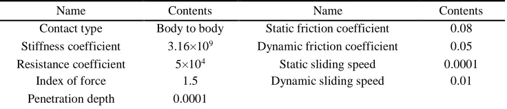
The tooth numbers z1 and z2 of pinion and large gear are 11 and 47. Contact force between tooth surfaces adopts solid
collision contact model base on impact function. According to related literatures, the parameter setting of contact parameters is shown in Table 1[1-3]. And parameters of load constrained under different conditions are shown in Table 2. Virtual prototype model of hypoid gear is gained finally, and it is shown in Fig. 1.
Table 1 Contact parameters
Name Contents Name Contents
Contact type Body to body Static friction coefficient 0.08
Stiffness coefficient 3.16×10⁹ Dynamic friction coefficient 0.05
Resistance coefficient 5×10⁴ Static sliding speed 0.0001
Index of force 1.5 Dynamic sliding speed 0.01
Penetration depth 0.0001
http://www.gjaets.com © Global Journal of Advance Engineering Technology and Sciences 53
Number Active
wheel
Follower wheel
Active surface
Follower surface
Load torque (N·m)
Rotational speed (r/min)
1 Pinion Large gear Concave of pinion Convex surface of large gear 1025 1000
2 Pinion Large gear Convex surface of pinion Concave of large gear 1025 1000
3 Large gear Pinion Concave of large gear Convex surface of pinion 240 234
4 Large gear Pinion Convex surface of large gear Concave of pinion 240 234
5 Pinion Large gear Concave of pinion Convex surface of large gear 1025 1000
Figure 1 Model of Cycloid Hypoid Gear Drive
Analysis Of Transmission Error Under Different Driving Conditions
Load and restraint shown in Table 2 are applied to drive system, and partial angular velocity of follower wheel under four conditions is shown in Fig. 2.
1) Transmission Error During Concave of Pinion Driving Convex Surface of Large Gear
Theoretical angular velocity of large gear is 24.4965rad/s, and the change of angular velocity with time is shown in Fig. 2(a). The entire oscillogram is fluctuating around root mean square value of 24.5043rad/s. Maximum, minimum and fluctuation amplitude are 25.8962rad/s, 22.9277rad/s and 2.9685rad/s. Compare root mean square value with theoretical value, we concluded that transmission error, relative error and fluctuation amplitude error are 0.0078rad/s, 0.031% and 12.118%.
2) Transmission Error During Convex Surface of Pinion Driving Concave of Large Gear
Theoretical angular velocity of large gear is 24.4965rad/s, and the change of angular velocity with time is shown in Fig. 2(b). The entire oscillogram is fluctuating around root mean square value of 24.5037rad/s. Maximum, minimum and fluctuation amplitude are 25.7453rad/s, 22.7199rad/s and 3.0254rad/s. Compare root mean square value with theoretical value, we concluded that transmission error, relative error and fluctuation amplitude error are 0.0072rad/s, 0.029% and 12.350%.
3) Transmission Error During Concave of Large Gear Driving Convex Surface of Pinion
Theoretical angular velocity of large gear is 104.6667rad/s, and the change of angular velocity with time is shown in Fig. 2(c). The entire oscillogram is fluctuating around root mean square value of 104.7026rad/s. Maximum, minimum and fluctuation amplitude are 110.4396rad/s, 97.2146rad/s and 13.225rad/s. Compare root mean square value with theoretical value, we concluded that transmission error, relative error and fluctuation amplitude error are -0.0359rad/s, 0.034% and 12.635%.
4) Transmission Error During Convex Surface of Large Gear Driving Concave of Pinion
http://www.gjaets.com © Global Journal of Advance Engineering Technology and Sciences 54
(a) Change of angular velocity with time for large gear when (b) Change of angular velocity with time for large gear concave of pinion driving convex surface of large gear when convex surface of pinion driving concave of large
gear
(c) Change of angular velocity with time for pinion when (d) Change of angular velocity with time for pinion when concave of large gear driving convex surface of pinion convex surface of large gear driving concave of pinion
Figure 2 Change of angular velocity with time for follower wheel
As can be seen from Fig. 2, output angular velocity curve of gear drive is fluctuating around root mean square value. Although transmission errors have little difference, fluctuation amplitude error increases sequentially as the conditions 1~4, which means fluctuation intensity gradually increases. As Fig. 2 (a)-(d) show that fluctuation frequency in Fig. 2(a) is relatively smaller. Therefore, from the point of view of fluctuation intensity and fluctuation frequency, transmission performance is relatively superior under condition 1.
Analysis on Angular Velocity Under Different Driving Conditions
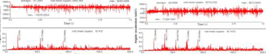
Load and restraint shown in Table 2 are applied to drive system, and changes of angular acceleration with time and with frequency for follower wheel under four conditions are shown in Fig. 3. The gear meshing frequency formula is[4-5]
/ 60
zf
N z
(1)In the equation,
f
z represents meshing frequency, Hz;N
represents rotational speed, rpm;z
represents tooth number. According to Table 1 and Table 2,f
z
183.3333
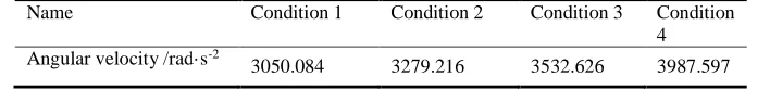
Hz, when pinion driving large gear and large gear driving pinion.Table 3 Root Mean Square Value of Angular Velocity in Time Domain Under Different Conditions
Name Condition 1 Condition 2 Condition 3 Condition
4 Angular velocity /rad·s-2
http://www.gjaets.com © Global Journal of Advance Engineering Technology and Sciences 55
(a)Time and frequency domain plot of angular velocity of large (b)Time and frequency domain plot of angular velocity of large gear when concave of pinion driving convex surface of large gear gear when convex surface of pinion driving concave of large gear
(c)Time and frequency domain plot of angular velocity of pinion(d)Time and frequency domain plot of angular velocity of pinion when concave of large gear driving convex surface of pinion when convex surface of large gear driving concave of pinion
Figure 3 Time and frequency domain plot of angular velocity of follower wheel
From time-domain plots shown in Fig. 3(a)-(d), the entire oscillogram is fluctuating around 0 rad/s-2. Fluctuation is
larger in the initial stage of simulation, while it is smaller without attenuation of fluctuation range when operation is stable, and because of gear drive with periodic internal incentive, fluctuation curve shows significant periodicity. In order to easily to compare Fig. (a) and Fig. (b), root mean square value in Fig. (c) and Fig. (d) are reduced to 4.273 times gear ratio and Table 3 is obtained. Effective value of angular acceleration in the time domain shows a gradually increasing tendency from condition 1 to condition 4, which shows effective value of angular acceleration, is the minimum; therefore, vibration is the minimum. Secondly, according to the frequency-domain plot, frequencies of first main peaks in Fig. 3(a)-(d) are close to meshing frequency of 183.3333Hz. Acceleration is the maximum in one time frequency, and there is main peak at three and five time frequency in Fig. 3(a). Acceleration is the maximum in two time frequency, and there is main peak at one and 3-5 time frequency in Fig. 3(b). Acceleration is the maximum in two time frequency, and there is main peak at one and four time frequency in Fig. 3(c). Acceleration is the maximum in three time frequency, and there is main peak at 1-2 time frequency in Fig. 3(d). Attenuation is more rapid and its dynamic performance is the best in frequency domain in Fig. 3(a). Time frequency domain and frequency domain are comprehensive analyzed; the dynamic meshing performance of cycloid hypoid gear drive is the best when concave of pinion driving convex surface of large gear.
Analysis on Angular Velocity of Advancing Surface and Backing Surface Under Different
Loads
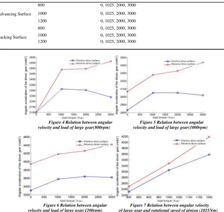
The parameters for simulation in ADAMS software are listed in Table 3. Effective value of angular acceleration under every condition is obtained by means of simulation, which is shown in Fig. 4-7. We can derive that effective value of angular acceleration increases with the increase of resistance loads for advancing surface and backing surface under the same rotational speed, becoming flat when resistance load reaches to a certain value, and the increasing amount for backing surface is larger than it for advancing surface;Effective value of angular acceleration increases with the increase of driving rotational speed for advancing surface and backing surface under the same resistance load, and the increasing amount for backing surface is larger than it for advancing surface. Therefore, the transmission performance for advancing surface is superior than it for backing surface.
Table 3 Design of load and rotational speed under different conditions
http://www.gjaets.com © Global Journal of Advance Engineering Technology and Sciences 56
Advancing Surface
800 0, 1025, 2000, 3000
1000 0, 1025, 2000, 3000
1200 0, 1025, 2000, 3000
Backing Surface
800 0, 1025, 2000, 3000
1000 0, 1025, 2000, 3000
1200 0, 1025, 2000, 3000
Figure 4 Relation between angular Figure 5 Relation between angular velocity and load of large gear(800rpm) velocity and load of large gear(1000rpm)
Figure 6 Relation between angular Figure 7 Relation between angular velocity velocity and load of large gear(1200rpm) of large gear and rotational speed of pinion (1025Nm)
Analysis On Noise From Gear Meshing
According to the dynamic analysis on cycloid hypoid gear drive and condition parameters shown in Table 4, time domain response curves of gear vibration acceleration in circumferential and radial direction are obtained by means of simulation in ADAMS software. And frequency domain response curve is obtained through FFT. Then, structural noise value of all calculating points for acceleration level 1/3 octave are obtained by means of 1/3 octave. Structural noise value for acceleration level 1/3 octave can be defined as [6-8]:
2 2
0 0
10 log 20 log
a
a a
L
a a
(2)
In the equation,
L
a represents the structural noise value for acceleration level 1/3 octave, and the unit is dB;a
represents effective value of acceleration for frequency ranges with cetain frequency as the central frequency, and the unit is m/s2;0
a
represents reference acceleration, anda
0=1×10-6(m/s2).http://www.gjaets.com © Global Journal of Advance Engineering Technology and Sciences 57
( ) /10
10lg[1 10
LpA LpB]
p pA
L
L
(3)In the equation,
L
p represents the composite sound pressure level, and the unit is dB, and the units ofL
pAandL
pBare also dB.
Table 4 Acceleration amplitude under different meshing frequency
Meshing
frequency(
Hz)
Load/(N·m)
Acceleration amplitude /(×10-4m/s2)
Advancing
circumferential Advancing radial
Backing circumferential Backing radial
146.6667
0 3.3998 4.3788 3.5096 4.4363
1025 8.193 7.8522 13 11
2000 13 14 16 27
3000 10 12 20 17
183.3333
0 1.328 2.7405 4.2542 5.83
1025 11 10 18 13
2000 20 21 26 24
3000 16 18 31 25
220
0 1.6134 1.8878 4.4295 4.0599
1025 14 13 21 16
2000 30 32 38 37
3000 25 26 45 39
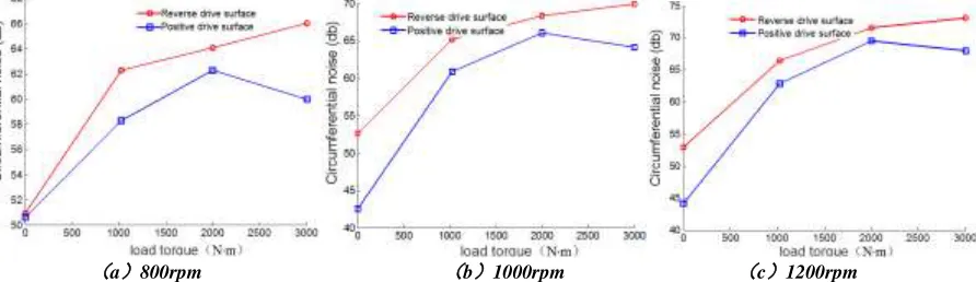
According to the equation (1), the corresponding meshing frequencies of 800rpm, 1000rpm and 1200rpm are 146.6667Hz, 183.3333Hz and 220Hz. The corresponding noise of acceleration amplitude shown in Table 4 is calculated, Figures 8~9 are obtained. It is suggested that the noise of backing is larger than it of advancing, and noise intensity increases with the increase of driving rotational speed; Noise intensity firstly increases and then gradually decreases with the increase of resistance load under the same rotational speed. The bigger the load, mainly because the larger the deformation of tooth surface, and the gear coincidence degree higher, which leads to the decrease of meshing impact and the noise intensity. Sound pressure levels from circumferential and radial are composed as the equation (4-3), and the corresponding noise figures are obtained, which are shown in Figures 8-9, the trend is similar to that from circumferential and radial, only numerical increases slightly.
(a)800rpm (b)1000rpm (c)1200rpm
http://www.gjaets.com © Global Journal of Advance Engineering Technology and Sciences 58
(a)800rpm (b)1000rpm (c)1200rpm Figure 9 Relation between radial noise and load
Conclusion
Multi-body dynamics simulation is conducted on cycloid hypoid gear in the rear driving axle main reducer in automobile, the change rules of contact parameters containing transmission error, time-domain plot and frequency-domain plot of angular acceleration were obtained under different driving conditions, including advancing, backing, neutral backing and neutral advancing. And the changes of angular acceleration, acceleration and noise intensity with resistance loads and rotational speed are also drawn when advancing and backing. The research shows that the tooth contact area and the contact force are stable, also, the dynamic meshing performance and the transmission performance are better when concave of pinion drives convex surface of large gear (advancing). The meshing stability is poor, and the damage and wear to the gear will increase under vehicle neutral operation, which provides a method for loaded tooth contact analysis (LTCA) and provides the basis for the designs of extended Epicycloid bevel gear and hypoid gear.
Acknowledgement
It is a Project supported by National Natural Science Foundation of China(Grant No:51375159); Key R & D Program of the science and Technology Department of Hunan Province(Grant No:2015JC3096); Project supported by Scientific Research in College Project of Hunan Province, (Grant No:12A038;13C379).
Reference
1. CHEN Si-yu, TANG Jin-yuan, XIE Yao-dong. Analysis of nonlinear impact dynamic behavior for a gear pair system with time-varying stiffness and friction[J]. JOURNAL OF VIBRATION AND SHOCK, 2009, 28(4): 70-75
2. Zhao Xiao-bo. The Reverse of Automobile Rear Axle Spiral Bevel Gear Tooth Surface and Dynamic Performance Analysis[D]. Chongqing: Chongqing University of Technology, 2014: 43-48
3. Zhang Zhi-min. DYNAMIC RESEARCH OF INFLUENCE OF GEAR ERRORS FOR SPIRAL BEVEL GEAR[D]. Beijing: Beijing University of Technology, 2013: 35-42
4. WANG Zhong-hou, WANG Jie, WANG Qiao-ling, et al. Transmission error of spiral bevel gear based on finite element method[J]. Journal of Vibration and Shock, 2014, 33(14):165-170
5. Wang Qing-yun. THE STUDY OF CAD & MODELING SYSTEM FOR KLINGELNBERG CYCLOID BEVEL GEARS[D]. Beijing: Beijing University Of Technology, 2006:15-32
6. Zhao Teng-long. Applications of ABAQUS6.6 to Mechanical Engineering[M]. Beijing: CHINA WATER POWER PRESS, 2007: 238-241
7. Yang Cheng-yun. Study on Coupled Vibration Response and Anti-impact Property of Gear Transmissions System[D]. Chongqing: Chongqing University, 2006:23-38
8. Leng Wen-ming. The Analysis of High-Speed Main Drive Axle Hypoid Reducer Gear[D]. Wunhan: Wuhan University of Technology, 2009:30-45
9. Kil-Young Ahn, Bong-Jo Ryu. A modeling of impact dynamics and its application to impact force predicition[J]. Proceedings of ACMD, 2004,3(2): 448-453
http://www.gjaets.com © Global Journal of Advance Engineering Technology and Sciences 59
The corresponding author: Ying He, born in Mar.1969, Female, Senior engineer, Dean of Resource Engineering Hunan Vocational Institute of Technology, Engaged in teaching and research in mechanical design. [email protected]