Effect Of Piled Raft Design On High-Rise
Building Considering Soil Structure Interaction
R. R. Chaudhari, Dr K. N. Kadam
Abstract: Piled-raft foundations for important high-rise buildings have proved to be a valuable alternative to conventional pile foundations or mat foundations. The concept of using piled raft foundation is that the combined foundation is able to support the a pplied axial loading with an appropriate factor of safety and that the settlement of the combined foundation at working load is tolerable. Pile raft foundation behavi or is evaluated with many researches and the effect of pile length; pile distance, pile arrangement and cap thickness are determined under vertical or horizontal static and dynamic loading. In the present paper the influence of pile length configurations on behavior of multi-storied are evaluated under vertical loading. In practice, the foundation loads from structural analysis are obtained without allowance for soil settlements and the foundation settlements are est imated assuming a perfectly flexible structure. However, the stiffness of the structure can restrain the displacements of the found ations and even tiny differential settlements of the foundations will also alter forces of the structural members. Hence, the interaction among structures, their foundations and the soil medium below the foundations alter the actual behaviour of the structure considerably than what is obtained from the consideration of the structure alone. In this work, analysis of pile soil structure interaction has been studied by finite element software ANSYS 11. The soil structure interact ion has been found to be significantly affecting the performance of structure and it is discussed in this paper.
Key words: ANSYS, FEM, interface, high rise building, pile configurations, pile raft foundation, soil structure interaction
————————————————————
1
I
NTRODUCTIONAccording to the advanced numerical analysis, the interaction between a raft, soil and the structure is considered. The response of any system comprising more than one component is always interdependent. For instance, a beam supported by three columns with isolated footing may be considered (Fig.1). Due to the higher concentration of the load over the central support, soil below it tends to settle more. On the other hand, the framing action induced by the beam will cause a load transfer to the end column as soon as the central column tends to settle more. Hence, the force quantities and the settlement at the finally adjusted condition can only be obtained through interactive analysis of the soil–structure– foundation system. This explains the importance of considering soil–structure interaction. The three-dimensional frame in superstructure, its foundation and the soil, on which it rests, together constitute a complete system. With the differential settlement among various parts of the structure, both the axial forces and the moments in the structural members may change. The amount of redistribution of loads depends upon the rigidity of the structure and the load-settlement characteristics of soil. Generally, it may be intuitively expected that the use of a rigorous model representing the real system more closely from the viewpoint of mechanics will lead to better results. But the uncertainty in the determination of the input parameters involved with such systems may sometimes reverse such anticipation.
Thus, to choose a detailed model, one should also be careful about the extent of accuracy with which the parameters involved with the model can be evaluated. In the present study, an attempt has been made to scrutinize the various approaches of modeling the soil–structure–foundation system and also compare the same highlighting their rigor and suitability for solving practical engineering problems with desired accuracy. In most of the civil engineering analysis, structure is assumed to be fixed at the base. Thus, the flexibility of foundation and the compressibility of the supporting soil medium are neglected. Consequently, the effect of uneven foundation settlements on redistribution of forces and moments in the superstructure is also neglected. Conventional structural design methods neglect the SSI effects. Neglecting SSI is reasonable for light structures in relatively stiff soil such as low rise buildings and simple rigid retaining walls. The effect of SSI, however, becomes prominent for heavy structures resting on relatively soft soils for example nuclear power plants, high-rise buildings and elevated-highways on soft soil. Hence, the attempt has been made to study the actual behavior of multi-storied building along with different types of soils. The building frame is considered under the gravity loading. Various pile length configurations are modeled and analyzed along with the building to study the optimum forces and moments in the building. Finally, different conclusions are drawn by studying the soil structure interaction.
Fig.1: Redistribution of loads in a frame due to soil–structure interaction.
———————————————
R. R. Chaudhari is currently pursuing Masters Degree Program in Structural Engineering in Govt. College of Engineering, Sant Gadge Baba University, Amravati, Maharashtra, India.
E-mail: [email protected]
Dr K. N. Kadam is currently Assistant Professor in Applied
Mechanics Department in Govt. College of Engineering, Amravati, Maharashtra, India.
73
interaction. Many other literatures were studied on the soil structure interaction. All the paper [6-14] restrains their work upto the soil settlements behavior. Very few authors have done their research on behavior of high rise building along with the soil pile interaction. Hence, taking in view the above research the further study in this paper is carried out on high rise building. Therefore, the author is trying to find the actual behavior of the structure with the soil pile interaction in terms of forces, displacements and moments.
3
D
IFFERENT TECHNIQUES OFSSI
ANALYSISMany numerical techniques has been developed to solve SSI problem such as, transmitting or absorbing boundaries of different kinds, boundary elements, infinite elements and their coupling procedures. The following are the techniques used for the soil – structure analysis.
a) Analytical method – The use of analytical method to analyze soil structure interaction problem requires the assumption of linear elastic homogenous half space and a regular foundation form. However, soil properties are rarely elastic. The actual soil is layered in nature and thus it is anisotropic material. It is very difficult to express anisotropy and non linearity in the analytical model.
b) Finite element method – Finite element method is one of the versatile methods for analysis of structure, as it is capable of modeling any irregularities in the structure, complex boundary conditions and linear as well as nonlinear behaviors. FEM is now a day‘s one of the most frequently used computational method in solving scientific and engineering problems. This is mainly due to the fact that FEM is able to reflect the original mathematical model in a very natural way. However, using a mesh of finite extent to model soil strata of theoretical infinite horizontal extent as well as deep soil deposits would create factious box effect trapping the wave absorbing boundaries has been invented to reproduce radiation of waves in to outer region.
c) Boundary element method - Boundary element method is essentially a semi analytical method. As only the boundary of the model needs to be modeled. Boundary integral representation is an exact representation of the problem and only approximation is those due to numerical implementation of this integral equation. This method is especially suitable for the problems involving infinite or semi – infinite domains because the Green‘s function used in the foundation automatically satisfies the radiation condition at the far field.
BEAM3 is a uniaxial element with tension, compression, and bending capabilities. The element has three degrees of freedom at each node, translations in the nodal x and y directions and rotation about the nodal z-axis. BEAM3 geometry shows the geometry, node locations and the coordinate system for this element (Fig.2). The element is defined by two nodes, the cross-sectional area, and the area moment of inertia.
Fig.2: BEAM3 (2-D Elastic Beam) Geometry
Fig.3: PLANE183 Geometry
c. Interface element
When the system of two different materials is to be analyzed, the stresses on the face of either element at their interface are unequal. This discrepancy is attributed to material incompatibility. Hence, it is necessary to introduce ‗interface elements‘ between the two materials, such that the actual interface stresses are obtained as the stresses in the elements. Interface elements are in the form of very thin membranes. Such interface elements are primarily used to simulate ‗perfectly smooth‘ or ‗perfectly rough‘ interfaces. A very high value of E is assigned to the elements in the direction normal to the contact surface and negligible values in the tangential directions, whereas the latter is obtained by assigning very high values of E to the elements in both directions. It may be noted that whereas tangential component of contact pressure can develop to any magnitude, the theoretical limit being infinity, in the case of a perfectly rough interface (no slip), no tangential component can exist in the perfectly smooth case (slipping). While these two are theoretical extremes, all practical cases fall under conditions of finite roughness where the tangential component (of force) can develop but not exceed the value of the normal component multiplied by the coefficient of friction.
5
F
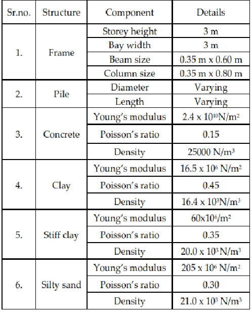
INITE ELEMENT ANALYSISTo study the contribution of pile length configurations with different soils on the behavior of building considering SSI, the parametric study with various soil types is done. The plan of the building with piles position is as shown in Fig.4. Simplified 2D finite element modeling and analysis is done for the pile raft system with structure. For this reason a strip i.e., section A-A is selected. Symmetrical four bay G + 11 storey frame having one pile supported under each column subjected to gravity load is modeled and analyzed using different cases i.e., changing the raft thickness, pile diameter and soil types. Depth of soil considered in the analysis is 41 m and the horizontal dimension is 63 m. Sizes of beam and column and the material parameters used in the analyses are tabulated in Table 1.
.
Fig.4: Plan of the building along with piles (All dimension are in m)
TABLE 1
Material and geometric properties of beam, column, raft, pile and soil
6
RESULTS AND DISCUSSIONS77
Fig.6: Total pile length for all the different pile configurations
From the Fig.6, it is observed that the quantities of concrete required for the zig-zag shape and for E1 model and V-shape are less than the other models. After that, the results are plotted in the graphs in terms of maximum moments (Mz) and the maximum vertical displacements (Uy). Fig.7 to Fig.9 shows the comparison of the maximum moments of all models with all the three soils viz., soft clay, stiff clay and silty sand. Fig.10 to Fig.12 presents the maximum vertical displacements in frame for each pile length combination.
Fig.7: Maximum moments on frame along with soft clay
Fig.8: Maximum moments on frame along with stiff clay
Fig.9: Maximum moments on frame along with silty sand
Fig.10: Maximum displacements on frame along with soft clay
Fig.11: Maximum displacements on frame along with stiff clay
Fig.12: Maximum displacements on frame along with silty sand
From Fig.10, Fig.11 and Fig.12, it is found that the values of maximum displacements are large in soft clay than silty sand. Also, it is clearly seen that the values of displacements for all
the models are nearby same for all types of soils individually. After studying all the models, the V-shape, U-shape and T-shape models give optimum results in terms of moments and displacements. Hence, Fig.13 presents total pile length for each V-shape, U-shape and T-shape pile length configuration.
Fig.13: Total pile length for V-shape, U-shape and T-shape pile configurations
7
CONCLUSIONSi. Due to the material discontinuity at the interface of the two different surfaces, the structure has to be modelled using the interface element.
ii. The maximum moments of soft clay are much larger than that of silty sand and stiff clay in all the cases. iii. The maximum settlements are less affected by soil
types.
iv. Moment carrying capacity of soil pile structure system is a function of-
a) Soil type b) Pile diameter c) Pile configuration d) Quantity of concrete
iv The values of maximum moments are less for the V-shape and U-V-shape models than the other models for all the soil types. Hence, the V-shape and U-shape models are optimum combination of pile length in terms of moments and also in terms of concrete quantity.
v It is also observed that the optimum configuration of pile is soil dependent. The best configuration varies from soil-to-soil.
79
[3] Meisam Rabiei, ―Piled Raft Design for High-Rise Building‖, M.sc of Geotechnical Engineering from Amir Kabir University of Technology, Tehran, Iran.
[4] Baleshwar Singh And Ningombam Thoiba Singh, ―Influence of Piles on Load Settlement Behaviour of Raft Foundation‖, International Journal of Engineering
Science and Technology (IJEST), December-2011,
8385-8395.
[5] S.P.Bajad and R. B. Sahu, ―An Experimental Study on the Behavior of Vertically Loaded Piled Raft on Soft Clay‖, International Association for Computer Methods
and Advances in Geomechanics (IACMAG),
October-2008, 1-6.
[6] G. Srilakshmi and B. Rekha, ―Analysis of MAT Foundation using Finite Element Method‖, International Journal of Earth Sciences and Engineering, October 2011, Vol. 04, 113-115.
[7] E.Y. N Oh, M. Huang, C. Surarak, R. Adamec And A. S. Balasurbamaniam, ―Finite Element Modeling For Piled Raft Foundation In Sand Eleventh”, East Asia-Pacific
Conference on Structural Engineering & Construction
(EASEC-11), November 2008, 19-21.
[8] M. Eslami, A. Aminikhah, M.M. Ahmadi, ―A comparative study on pile group and piled raft foundations (PRF) behavior under seismic loading‖, Computational
Methods in Civil Engineering , October 2011, 185-199.
[9] Prishati Raychowdhury, ―Seismic response of low-rise steel moment-resisting frame (SMRF) buildings is incorporating nonlinear soil–structure interaction (SSI)‖,
Engineering Structures 33, 2011, 958–967.
[10]H. Alawaji, ―Numerical Modeling and Analysis of Micro Piled Square Footing in Silty Sand over Limestone Rock in Riyadh”, International Conference of
International Association for Computer Methods and
Advances in Geomechanics (IACMAG), October 2008,
1-6.
[11]Sekhar Chandra Dutta and Rana Roy, ―A critical review on idealization and modeling for interaction among soil–foundation–structure system‖, Computers and
Structures, 2002, 1579–1594.
Environmental Engineering, Amirkabir University of
Technology, Tehran, Iran, November 2011, Vol.2,