Department of Telematics Engineering
Control-Theoretic Adaptive Mechanisms for
Performance Optimization of IEEE 802.11 WLANs:
Design, Implementation and Experimental Evaluation
Author: Paul Horat»iu P˘atras», M.Sc. Advisor: Albert Banchs Roca, Ph.D.
Legan´es, Madrid, Spain March 2011
He to whom this emotion is a stranger, who can no longer pause to wonder and stand rapt in awe, is as good as dead: his eyes are closed.
First and foremost, I would like to thank my advisor, Albert Banchs, for his invaluable guidance and insightful suggestions, which contributed to the success of my work. He has been truly a model, teaching me how to tackle the most difficult problems, develop self-confidence and always be determined to overcome the obstacles in my research.
I am extremely grateful to my colleague and dear friend Pablo, who always had his door open for me, constantly challenged me over the past years, was always enthusiastic about working on new ideas and with whom I also spent unforgettable moments outside the campus.
I thank Arturo Azcorra for his valuable feedback on my work and for giving me the opportunity to collaborate with other research groups. I acknowledge Institute IMDEA Networks for funding my Ph.D. and all the institute’s staff, but especially Rebeca and Jos´e F´elix, for providing me support in administrative matters, which helped me devote more time to my research. I would like to thank my colleagues from the NETCOM group for the great collaboration within the DAIDALOS and CARMEN research projects, and in particular Carlos Jes´us, Andr´es and Antonio, who stood by me with friendship and support in many practical issues. I also appreciate the collaboration with Vincenzo, Andrea and Marco, who helped me with the testbed deployment, measurements and important comments.
I am grateful to Edward Knightly for hosting me at Rice University, for involving me in fruitful debates and focusing my research. I also thank Tasos for his collaboration on wide-spectrum networks research, as well as Cen, Naren, Eugenio, Ryan and Misko for the useful discussions and the good time spent together while working with the Rice Networks Group.
For countless reasons I thank my friends Vali, Sorin, Ionut, Cristi and Cosmin. And in particular, I thank my loving girlfriend, Mariana, whose encouragements, patience and joy have been very important to me in the final stages of this Ph.D.
Finally, but most of all, I thank my family for their endless love and support through-out the years, for believing in me and encouraging my pursuits.
The media access control (MAC) layer of the IEEE 802.11 standard specifies a set of parameters that regulate the behavior of the wireless stations when accessing the channel. Although the standard defines a set of recommended values for these parameters, they are statically set and do not take into account the current conditions in the wireless local area network (WLAN) in terms of, e.g., number of contending stations and the traffic they generate, which results in suboptimal performance. In this thesis we propose two novel control theoretic approaches to optimally configure the WLAN parameters based on the dynamically observed network conditions: aCentralized Adaptive Control (CAC)
algorithm, whereby the access point (AP) computes the configuration that maximizes performance and signals it to the active stations, and a Distributed Adaptive Control (DAC) algorithm, which is independently employed by each station with the same goal.
In contrast to previous proposals, which are mostly based on heuristics, our approaches build upon (i) analytical models of the WLAN performance, used to derive the optimal point of operation of the IEEE 802.11 protocol, and (ii) mathematical foundations from single- and multi-variable control theory, used to design the mechanisms that drive the WLAN to this point of operation. Another key advantage of the proposed algorithms over existing approaches is that they are compliant with the IEEE 802.11 standard and can be implemented with current wireless cards without introducing any modifications into their hardware and/or firmware. We show by means of an exhaustive performance evaluation study that our algorithms maximize the WLAN performance in terms of throughput and delay under a wide set of network conditions, substantially outperforming the standard recommended configuration as well as previous adaptive proposals.
Finally, we present our experiences with implementing the proposed adaptive algo-rithms in a real IEEE 802.11 testbed and discuss the implementation details of the build-ing blocks that comprise these mechanisms. We evaluate their performance by conductbuild-ing extensive measurements, considering different network conditions in terms of number of nodes, transmission power employed and traffic generated. Based on the obtained re-sults, we provide valuable insights on the performance of the distributed and centralized algorithms and discuss the suitability of these schemes for real deployments.
Acknowledgments i
Abstract iii
Contents vii
List of Figures xi
1 Introduction 1
1.1 Summary of Thesis Contributions . . . 3
1.2 Thesis Overview . . . 4
2 Background 7 2.1 IEEE 802.11 EDCA . . . 7
2.2 Related Work . . . 10
3 Centralized Adaptive Control Algorithm 13 3.1 Data Traffic Scenario . . . 13
3.1.1 Throughput Analysis and Optimization . . . 14
3.1.2 CAC Algorithm . . . 17
3.1.3 Performance Evaluation . . . 23
3.2 Real-Time Traffic Scenario . . . 30
3.2.1 Analytical Model . . . 31
3.2.2 CAC–VI Algorithm . . . 36
3.2.3 Performance Evaluation . . . 41
4 Distributed Adaptive Control Algorithm 59
4.1 DAC Algorithm . . . 60
4.2 Steady State Analysis . . . 63
4.3 Stability Analysis . . . 65
4.4 Performance Evaluation . . . 69
4.4.1 Saturated Scenario . . . 70
4.4.2 Non-saturated Scenario . . . 70
4.4.3 Mixed Scenario . . . 71
4.4.4 Convergence . . . 72
4.4.5 Stability and Speed of Reaction to Changes . . . 74
4.4.6 Fairness . . . 76
4.5 Summary . . . 77
5 Experimental Evaluation 79 5.1 Implementation Details . . . 79
5.1.1 CAC Algorithm . . . 80
5.1.2 DAC Algorithm . . . 81
5.1.3 Hardware & Software Platform . . . 82
5.1.4 Implementation Overview . . . 83
5.1.5 Estimation of pobs . . . 84
5.1.6 Estimation of pown . . . 84
5.1.7 Contention Window Update . . . 85
5.2 Performance Evaluation . . . 86
5.2.1 Testbed & Evaluation Methodology . . . 86
5.2.2 Practical Validation of the Algorithms’ Operation . . . 89
5.2.3 Impact of Link Quality on Throughput Distribution . . . 91
5.2.4 Impact of Hidden Nodes . . . 95
5.2.5 Impact of Network Size . . . 96
5.2.6 Impact of Dynamic Traffic Conditions . . . 98
6 Conclusions and Future Work 103
References 113
2.1 Example of EDCA operation with 2 stations. . . 8
2.2 Retry flag marking upon collisions. . . 9
3.1 Control system. . . 18
3.2 Linearized system. . . 21
3.3 Throughput performance. . . 23
3.4 Stable configuration. . . 25
3.5 Unstable configuration. . . 25
3.6 Speed of reaction to changes. . . 26
3.7 Instantaneous throughput. . . 26
3.8 Non-saturated stations. . . 27
3.9 Bursty traffic. . . 28
3.10 Comparison against other approaches. . . 28
3.11 Impact of channel errors. . . 29
3.12 Markov chain model of the WLAN. . . 33
3.13 Control system. . . 37
3.14 Linearized system. . . 40
3.15 Validation of the delay model. . . 42
3.16 Optimal collision probability. . . 43
3.17 CW configuration. . . 43
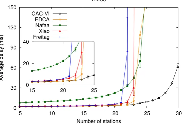
3.18 Delay performance of the proposed algorithm . . . 44
3.20 Speed of reaction to changes. . . 46
3.21 Time evolution of the error signal. . . 46
3.22 Delay performance for different TXOP. . . 47
3.23 Average, 90th and 95th percentiles of the access delay. . . 48
3.24 Total delay vs. access delay. . . 49
3.25 Burstiness vs average delay. . . 49
3.26 Support for graceful degradation of video flows. . . 50
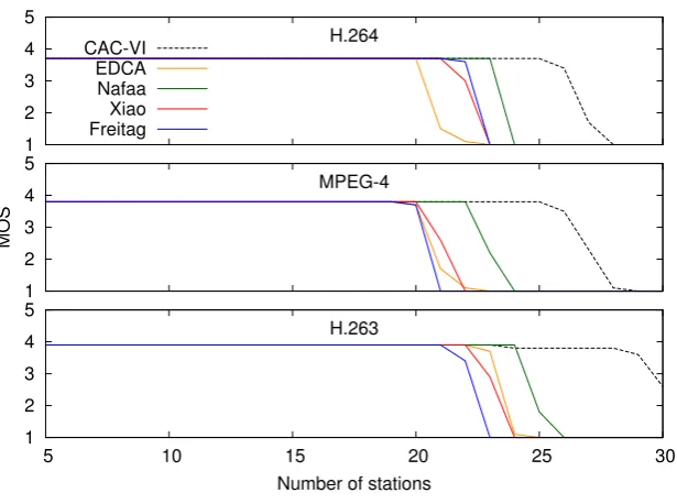
3.27 Comparison against other approaches: H.264 video. . . 51
3.28 Comparison against other approaches: MPEG-4 video. . . 51
3.29 Comparison against other approaches: H.263 video. . . 52
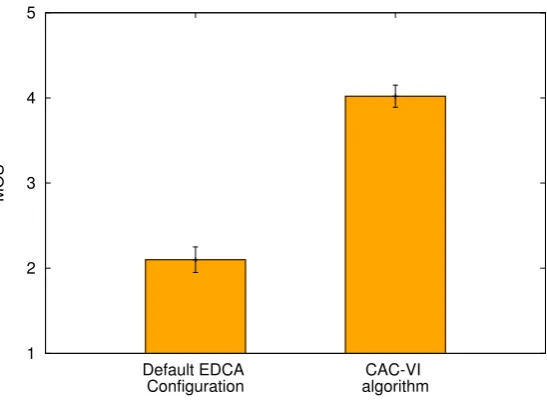
3.30 MOS evaluation. . . 53
3.31 Delay performance under channel errors. . . 54
3.32 Delay performance under mixed traffic. . . 55
3.33 MOS evaluation with real users. . . 55
3.34 Sample video frame with the default EDCA configuration. . . 56
3.35 Sample video frame with the proposed CAC–VI algorithm. . . 56
4.1 DAC Algorithm . . . 60
4.2 Control system . . . 65
4.3 Saturated scenario . . . 70
4.4 Non-saturation scenario . . . 71
4.5 Throughput performance under mixed traffic conditions . . . 72
4.6 Average delay under mixed traffic conditions . . . 73
4.7 Throughput performance of the mixed unbalanced scenario . . . 73
4.8 Average delay of the mixed unbalanced scenario . . . 74
4.9 Convergence . . . 74
4.10 Stability validation . . . 75
4.11 Speed of reaction to changes . . . 75
5.1 CAC algorithm. . . 80
5.2 DAC algorithm . . . 81
5.3 Hardware platform . . . 82
5.4 CAC and DAC implementations . . . 83
5.5 Deployed testbed. . . 87
5.6 CAC: Announced CWmin . . . 88
5.7 CAC: Observed collision probability . . . 88
5.8 DAC: CWmin used by four nodes . . . 90
5.9 DAC: Estimated pobs and pown . . . 90
5.10 Total throughput with heterogeneous link qualities . . . 91
5.11 Throughput per station with heterogeneous link qualities . . . 92
5.12 Jain’s fairness index with heterogeneous link qualities . . . 92
5.13 Throughput per station with quasi-homogeneous link qualities . . . 93
5.14 Jain’s fairness index with quasi-homogeneous link qualities . . . 94
5.15 Total throughput with quasi-homogeneous link qualities . . . 94
5.16 Throughput performance with hidden nodes . . . 96
5.17 Total throughput for different number of stations . . . 97
5.18 Jain’s fairness index for different number of stations . . . 98
5.19 CAC: CWmin behavior under increasing number of stations . . . 99
5.20 DAC: CWmin behavior under increasing number of stations . . . 99
Introduction
The IEEE 802.11 standard for Wireless LANs [1] has become one of the most widely deployed technologies for providing broadband connectivity to the Internet in the recent years. The reduced investment costs (facilitated by the use of unlicensed spectrum and the availability of low cost devices), the deployment flexibility and unpretentious management have lead to the emergence of a substantial number of WiFi Access Points, used not only in office environments or as public hot-spots but also to connect residential users and their multimedia devices to the Internet. As a consequence, today’s wireless access deployments based on IEEE 802.11 vary from small scale networks installed in airports, caf´es and universities, to larger scale public and commercial ones, such as Google WiFi1 or TFA Wireless.2
The IEEE 802.11 standard [1] defines two different channel access mechanisms, a centralized one, known as the Point Coordination Function (PCF), and a distributed one, the Distributed Coordination Function (DCF). However, most of the current WLANs are based on the latter, i.e., a CSMA/CA protocol that only provides a best effort service, while the PCF mechanism has received relatively little attention from manufacturers.
To satisfy the increasing bandwidth demands, the basic physical layer specification of 2 Mbps capacity [2] has been extended, to provide up to 11 Mbps nominal throughput with IEEE 802.11b [3] and up to 54 Mbps with IEEE 802.11a [4] and IEEE 802.11g [5]. This rate increase has enabled the use of WLANs also for real-time applications, such as, e.g., Voice over IP (VoIP), video streaming or video conferencing. (Note that today’s laptops already have an integrated webcam.) However, these bandwidth and delay sensitive applications are properly supported only in over-provisioned scenarios, where the best-effort based scheme of DCF is enough to fulfill the QoS requirements.
In order to overcome this limitation, the revised version of the standard specifies
1
http://wifi.google.com/ 2
http://tfa.rice.edu/
an improved channel access scheme, the Hybrid Coordination Function (HCF), which consists of two access mechanisms, the HCF Controlled Channel Access (HCCA) and the Enhanced Distributed Coordination Access (EDCA) [6]. The former is based, like PCF, on a centralized controller that schedules the transmissions in the WLAN, while the latter is an extension of DCF that supports service differentiation through four different Access Categories (namely voice, video, best-effort and background). These Access Categories can be configured with different values of the contention parameters, leading to statistical service differentiation. However, the configuration of both mechanisms is left open, as the standard only specifies a simple scheduler to provide constant bit rate (CBR) services for the case of HCCA, and a set of recommended values of the contention parameters for the case of EDCA.
The fixed set of recommended values for the EDCA parameters employed by the standard is statically set, which results in poor throughput and delay performance for most scenarios, as the optimal configuration of the channel access parameters depends on the WLAN conditions, these including the number of stations and their load [7– 9]. In particular, if too many stations contend with overly small Contention Window (CW) values,3 the collision rate will be very high, which yields a degraded performance. Similarly, if few stations contend with too large CW’s, the attempt rate will be low and the channel will be underutilized most of the time, leading to poor performance also in this case.
In order to avoid this undesirable behavior, many schemes have been proposed in the literature to dynamically adapt the CW to the current WLAN conditions. This approaches can be classified as either centralized or distributed mechanisms. On one hand, centralized approaches [10–14] are based on a single node (the Access Point) that periodically computes the set of MAC layer parameters to be used and signals this con-figuration to all stations. On the other hand, with distributed approaches [15–21] each station independently computes its own configuration.
However, these previous works4 suffer from at least one of the following key limita-tions: (i) they are based on heuristics and therefore lack the mathematical foundations to guarantee optimal performance; (ii) they rely on functionality that is not available with existing wireless devices, requiring modifications of their hardware and/or firmware;
(iii) their performance has not been assessed with real deployments, and therefore lack experimental evidences gathered from scenarios with channel impairments and implemen-tation constraints.
In contrast to the previous proposals, in this thesis we develop analytical models of the WLAN performance, derive the optimal point of operation of the IEEE 802.11 protocol
3
The description of the IEEE 802.11 EDCA mechanism is provided in Sec. 2.1
4
in terms of throughput and delay, and propose a centralized and a distributed adaptive algorithm, which are sustained by mathematical foundations from single-/multi-variable control theory. We show that these algorithms are able to drive the WLAN to its optimal point of operation and have the additional key advantage over existing approaches of being compliant with the IEEE 802.11 standard, as they can be implemented by current devices without introducing any modifications into their hardware and/or firmware.
1.1
Summary of Thesis Contributions
The contributions of this thesis are summarized as follows. First, we conduct an analysis of the WLAN saturation throughput and we derive the collision probability of an optimally configured WLAN. Based on this analysis, we propose a novel adaptive algorithm, the Centralized Adaptive Control (CAC) [22, 23], which dynamically adjusts the CW configuration of IEEE 802.11 stations with the goal of maximizing the overall throughput performance of the wireless network. Compared to the existing schemes, our proposal is fully compatible with the IEEE 802.11 standard, since the dynamic adjust-ment is based only on observing successfully received frames at the Access Point (AP).
CAC is based on a well established scheme from discrete-time control theory, namely the
Proportional Integrator (PI) controller. By conducting a control theoretic analysis of the system we tune the parameters of the PI controller to achieve a good tradeoff between stability and speed of reaction to changes.
Second, we propose an analytical model of the WLAN performance under video traffic, used to derive the optimal point of operation of EDCA with real-time sources. Based on this analysis we extend CAC to dynamically adjusts the CW configuration of the WLAN with the goal of minimizing the average delay, which results in a better quality of experience (QoE) of the video traffic [24]. In addition to being standard complaint and having mathematical foundations that guarantee optimal performance, the algorithm supports graceful degradation of video flows by implementing a priority based dropping policy, in line with the efforts of IEEE 802.11aa Task Group for robust streaming of audio-video transport streams.
Third, we propose a distributed approach to the optimal configuration of 802.11 WLANs, which shares the same goal of maximizing the overall performance as the central-ized scheme [25]. The key novelty of the proposed Distributed Adaptive Control (DAC)
guar-antee convergence and stability while ensuring a quick reaction to changes, (ii) it is standard-compliant as it only relies on functionality available with existing cards, and
(iii) in contrast to existing schemes, which modify the contention parameters of all sta-tions upon congestion, our algorithm only acts on those stasta-tions that are contributing to congestion, providing stations that are not contributing to congestion with a better delay performance.
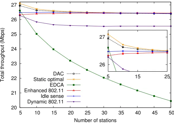
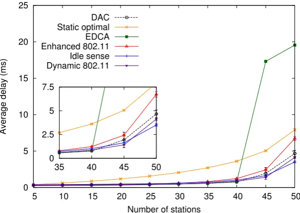
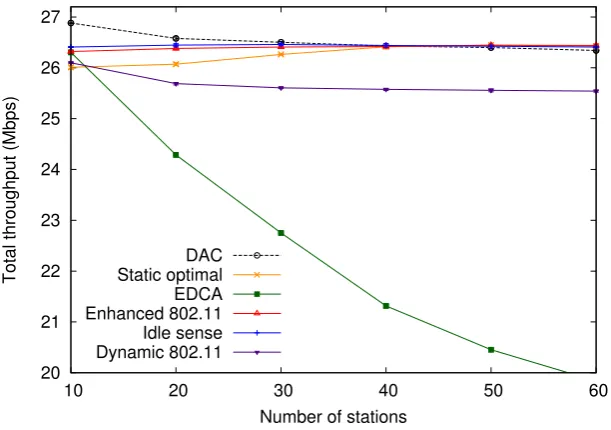
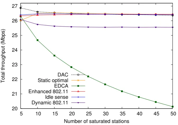
We undertake a thorough simulation study to evaluate the proposed algorithms and compare their performance against the standard IEEE 802.11 mechanism, as well as previ-ous adaptive approaches. As a benchmark for assessing the performance of our algorithms we also consider the static optimal configuration obtained with the algorithm we proposed in [26]. Note that, although the solution in [26] considers a more general scenario with different traffic types, its limitation lies within the fact that it requires a priori knowledge of the number of stations and the specific requirements of the applications, which involves additional signaling between the stations and the AP, while the algorithms proposed in this thesis do not rely on such information. The results of the evaluation show that(i)the proposed schemes outperform substantially both the standard 802.11 mechanism and ex-isting proposals in terms of throughput, (ii) they provide a better delay performance than the previous adaptive schemes, and (iii) the configuration of the parameters of the PI controllers employed is adequate, as with other settings, the system either becomes unstable or reacts too slowly to changes.
Finally, we present our experiences gained with implementing the two adaptive al-gorithms and demonstrate that they can be easily deployed with unmodified existing hardware. We provide a detailed description of the implementation of the proposed mechanisms, which run as user space applications, relying on standardized system calls to estimate the contention level in the WLAN and to dynamically adjust theCW. We also give insights on the differences between the theoretical and practical implementations of the algorithms, which arose with the inherent limitations of the real devices, and prove the feasibility of utilizing these algorithms with existing commercial off-the-shelf (COTS) hardware and open-source device drivers. By conducting exhaustive experiments in a medium-scale testbed, we evaluate the performance of our proposals under non-ideal channel effects and different traffic conditions. Additionally, we compare the performance of our algorithms against the default 802.11 mechanism to identify those scenarios where a network deployment can benefit from using such adaptive algorithms [27].
1.2
Thesis Overview
Background
IEEE 802.11 is the de facto standard currently used for providing users with wire-less access to private networks and the Internet. In this chapter we first summarize the Enhanced Distributed Channel Access (EDCA) mechanism as specified by the revised version of the IEEE 802.11 standard [1] and then discuss the most relevant related works on WLAN performance modeling, adaptive MAC mechanisms and experimental evalu-ation studies, highlighting the key differences between previous research efforts and the contributions we present in this thesis.
2.1
IEEE 802.11 EDCA
EDCA regulates the access to the wireless channel on the basis of the channel access functions (CAFs). A station may run up to 4 CAFs, and each of the frames generated by the station is mapped to one of them. Once a station becomes active, each CAF executes an independent backoff process to transmit its frames.
A station with a new frame to transmit monitors the channel activity. If the medium is idle for a period of time equal to the arbitration interframe space parameter (AIF S), the CAF transmits. Otherwise, if the channel is sensed busy (either immediately or during theAIF S period), the CAF continues to monitor the channel until it is measured idle for an AIF S time, and, at this point, the backoff process starts. The arbitration interframe space takes a value of the form DIF S +kTe, where DIF S (the distributed interframe
space) and Te are constants dependent on the physical layer and k is a non-negative
integer.
Upon starting the backoff process, a random value uniformly distributed in the range [0, CW−1] is chosen and the backoff time counter is initialized with this number. TheCW
Start backoff Unif[0,CWmin-1]
St. 1
St. 2
SIFS
ACK AIFS
New
packet AIFS
Tx frame 7654
Freeze counter
SIFS
ACK AIFS medium busy
Reactivate counter
3210 3210
Collision
Figure 2.1: Example of EDCA operation with 2 stations.
of a frame. At the first transmission attempt,CW is set equal to the minimum contention window parameter (CWmin).
As long as the channel is sensed idle, the backoff time counter is decremented once every empty slot time Te. When a transmission is detected on the channel the backoff
time counter is “frozen”, and reactivated again after the channel is sensed idle for a certain period. This period is equal toAIF Sif the transmission is received with a correct Frame Check Sequence (FCS), andEIF S−DIF S+AIF Sotherwise, whereEIF S(the extended interframe space) is a physical layer constant.
As soon as the backoff time counter reaches zero, the CAF transmits its frame. A collision occurs when two or more CAFs start transmitting simultaneously. An acknowl-edgment (ACK) frame is used to notify the transmitting station that the frame has been successfully received. The ACK is immediately sent upon the reception of the frame, after a period of time equal to the physical layer constant SIFS (the short interframe space). The operation of EDCA is illustrated in Fig. 2.1.
If the ACK is not received within a time interval given by theACK T imeoutphysical layer constant, the CAF assumes that the frame was not received successfully. The transmission is then rescheduled by reentering the backoff process, which starts at an
AIF S time following the timeout expiry. After each unsuccessful transmission, CW is doubled, up to a maximum value given by the CWmax parameter. If the number of
failed attempts reaches a predetermined retry limit R, the frame is discarded. In order to prevent duplicates, the IEEE 802.11 standard uses a retry bit Rto mark those frames that are being retransmitted, i.e., the flagR is set to 0 on the first transmission attempt, and set to 1 on every other transmission (see Fig. 2.2).
Figure 2.2: Retry flag marking upon collisions.
backoff time counters of two or more CAFs reach zero at the same time, a scheduler inside the station avoids the internal collision by granting the access to the channel to the highest priority CAF. The other CAFs of the station involved in the internal collision react as if there had been a collision on the channel, doubling their CW and restarting the backoff process.
After a (successful or unsuccessful) frame transmission, before sending the next frame, the CAF must execute a new backoff process. As an exception to this rule, the protocol allows the continuation of an EDCA transmission opportunity (TXOP). A continuation of an EDCA TXOP occurs when a CAF retains the right to access the channel following the completion of a transmission. In this situation, the station is allowed to send a new frame a SIFS period after the ACK corresponding to the completion of the previously transmitted frame. The period of time a CAF is allowed to retain the right to access the channel is limited by the transmission opportunity limit parameter (T XOP limit).
Hence, the behavior of a CAF depends on a number of parameters, namely CWmin,
CWmax, AIF S and T XOP limit. These are configurable parameters that can be set
to different values for different CAFs. The CAFs are grouped by Access Categories (ACs), all the CAFs of an AC having the same configuration. In order to provide service differentiation the IEEE 802.11 standard recommends different values for the channel access parameters, listed in Table 2.1 for the case of IEEE 802.11b [3] physical (PHY) layer.1 Apart from this recommended set of values, the standard also specifies that the Access Point (AP) can periodically broadcast through beacon frames (every 100 ms) the
Access category AIF S CWmin CWmax T XOP
voice DIF S 8 16 3.264ms
video DIF S 16 32 6.016ms
best-effort DIF S+T e 32 1024 0 background DIF S+ 5T e 32 1024 0
Table 2.1: Default EDCA configuration for 802.11b PHY.
1
EDCA parameters to be used by all stations.
Following the above, when deploying an EDCA WLAN, the main challenge is the configuration of the contention parameters, as the standard set of recommended values remains the same for every scenario, regardless of, e.g., the number of stations or their traffic patterns, which leads to suboptimal performance in most circumstances. Next we discuss the previous research efforts in the literature that address the aforementioned challenge by proposing analytical models for the WLAN performance, mechanisms for the configuration of the EDCA parameters to improve performance, adaptive MAC schemes and experimental studies.
2.2
Related Work
Analytical models. Several analytical models of DCF/EDCA performance have been proposed in the literature [7, 9, 28–42]. Most of them [9, 28–35] are based on the as-sumption that all stations always have packets ready for transmission (commonly referred to as saturation conditions). While this assumption may be reasonable for data traffic, it does not hold for real-time traffic. On the other hand, previous models assuming non-saturated conditions have also been developed, considering different types of scenarios including Poisson arrival processes, voice traffic, video sources, etc. [36–42].
In contrast to the above proposals, our recent work of [26] does not make any as-sumption about the arrival process and allows for variable packet lengths, providing more comprehensive analyses of EDCA, which include generic traffic sources as well as the rel-evant metrics for data and real-time traffic (namely throughput, average and standard deviation of the delay). In this thesis we leverage our data analysis in [26] and we build on the analytical model presented in [41] to develop control-theoretic mechanisms that optimize the total throughput and the average delay, respectively.
EDCA configuration proposals. As the 802.11 standard allows for the default MAC configuration to be changed, the challenge of tuning the EDCA parameters when the network conditions are foreknown has been addressed recently in the literature [9, 43–48]. The works of [9] and [45] are restricted to data traffic, while the proposals of [43] and [44] are restricted to voice traffic. On the other hand, the approaches developed in [46] and [47] consider two traffic types, voice and data, but do not account for other types. In contrast, the configuration recommended in [48] considers all types of traffic, but it is based on a heuristic and therefore does not guarantee optimal performance.
lacking analytical support for providing performance guarantees [10–12], or they do not consider the dynamics of the WLAN under realistic scenarios [13, 14]. Moreover, some of these approaches [13,14] require to estimate the number of stations, which adds additional complexity to the APs that have limited computational resources, thus challenging their practical use.
Distributed approaches. Several works have proposed mechanisms that indepen-dently adjust the backoff operation of each stations in the WLAN [15–21,49]. A significant drawback of most of these algorithms is that they require substantial modifications to the hardware and/or firmware of the existing wireless cards. The approaches of [15, 16] use as input low level data, which is currently not available with existing cards, and require mod-ifying the CW on a per-packet basis, which is not possible with current interfaces, thus bringing substantial complexity. The work of [17] is based on control theory, but models the WLAN as a single variable system, and therefore assumes a simplistic scenario where all stations simultaneously join the WLAN. Furthermore, the proposals of [16,18,49] mod-ify the contention algorithm of IEEE 802.11, which is not supported by current devices.
Implementation experiences and experimental studies. Very few schemes that address the optimization of the WLAN performance have been developed in practice [14, 50, 51]. While the idea behind Idle Sense [16] is fairly simple, its implementation [50] entails a significant level of complexity, introducing tight timing constrains that require programming at the firmware level. The work of [51] prototypes the approach of [20] in a small testbed with four stations. The main weaknesses are that the performance evaluation is only limited to simple network conditions and the solution modifies the IEEE 802.11 state machine. The work of [14] presents an experimental study on a medium-sized testbed to obtain the CWmin that achieves proportional fairness. However, similar
to [51], the experiments are only performed under static conditions.
Key advantages of the proposed work. In contrast to the above mentioned approaches, the algorithms proposed in this thesis hold the following assets:
CAC and DAC utilize input data readily available from existing cards and rely on standardized primitives for theCW configuration,
The algorithms that compute theCW have relaxed timing constraints2 and do not require any firmware level programming. Indeed, as reported in Chapter 5, our implementations have been realized entirely at the user space level and we have been able to deploy them with a relatively low effort,
2While the functionality of previous works impose tight constraints, being typically executed on a
The configuration of the algorithms’ parameters has been obtained analytically, which guarantees optimal performance. In contrast, previous approaches have ob-tained the configuration of some of their parameters either heuristically or empiri-cally. The major drawback of such a parameter settings is that they cannot provide any guarantees on the performance of the algorithm for general scenarios; for in-stance, stability is not guaranteed by any of these approaches,
In contrast to the previous works, we investigate the performance of the proposed
CAC and DAC algorithms under a wide set of network conditions and provide valuable insights on their suitability for deployment in practical environments.
Centralized Adaptive Control
Algorithm
In this chapter we propose a novel centralized algorithm, which relies on analytical models of the WLAN operation and foundations from control theory to guarantee optimal performance for general scenarios. In the first part, we address the challenge of maximizing of the total throughput of the WLAN, when stations transmit data traffic and propose the Centralized Adaptive Control (CAC) algorithm, which dynamically adjusts the CW
configuration of IEEE 802.11-based Wireless LANs to achieve this goal. For this purpose, we provide an analytical model of the IEEE 802.11 EDCA behavior, which we use to design the mechanism that tunes the CWmin with which stations contend to achieve the
optimal operation. Second, we investigate the case in which stations transmit real-time traffic, and extend CAC with the goal of minimizing the average delay, and therefore provide end users with a better Quality of Experience (QoE) of video traffic. To this aim, we model the WLAN behavior under video traffic and compute its optimal point of operation in this scenario. Based on this analysis, the extended CAC-VI algorithm tunes the CW of the video stations to drive the wireless network to this optimal point and thereby minimizes the access delay.
3.1
Data Traffic Scenario
As discussed in Sec. 2.1 the contention window configuration recommended by the IEEE 802.11 standard [1] is statically set, independently of the number of contending stations, thus yielding poor performance in most scenarios. In particular, when there are many stations in the WLAN, it would be desirable to use largeCW values, in order to avoid too frequent collisions, while with few stations smaller CWs would reduce the
channel idle time.
Following the above observation, many authors have proposed centralized approaches [10–14] that dynamically adapt the CW by estimating the number of active stations in the WLAN in order to improve the throughput performance. These mechanisms are based on a single node, the Access Point, that periodically computes and distributes the set of MAC layer parameters to be used by every station. Since these approaches are executed on the AP, they do not require any modifications at the stations, therefore have the advantage of being compatible with the IEEE 802.11 standard. However, because they are based on heuristics and lack analytical support, they do not guarantee optimal performance.
The novel adaptive algorithm that we propose shares the same goal of maximizing the overall throughput performance of the wireless network by adjusting theCW, but, in contrast to previous approaches, it benefits from the following key improvements:
1. It does not require estimating the number of active stations, as the dynamic adjust-ment is solely based on observing successfully received frames at the AP.
2. It is based on a well established scheme from discrete-time control theory, namely the Proportional Integrator (PI) controller [52], whose parameters we compute by conducting a control theoretic analysis of the system, to achieve a proper tradeoff between stability and speed of reaction to changes.
3.1.1 Throughput Analysis and Optimization
In this subsection we present a throughput analysis of an EDCA WLAN. Based on this analysis, we find the collision probability of an optimally configured WLAN, which is the basis of the CAC algorithm. We start by analyzing the case when all stations are saturated and consider later the case when some stations are not saturated.
Let us define τ as the probability that a saturated station transmits in a randomly chosen slot time. This can be computed according to [7] as follows:
τ = 2
1 +W +pWPm−1
i=0 (2p)i
(3.1)
whereW is theCWmin,mis the maximum backoff stage (CWmax = 2mCWmin) andpis
the probability that a transmission collides. In a WLAN with nstations, this is given by
The throughput obtained by a station can be computed as follows
r= Psl
PsTs+PcTc+PeTe
(3.3)
wherelis the packet length,Ps,PcandPeare the probabilities of a success, a collision and
an empty slot time, respectively, andTs,TcandTe are the respective slot time durations.
The probabilities Ps,Pcand Pe are computed as
Ps=nτ(1−τ)n−1 (3.4)
Pe= (1−τ)n (3.5)
Pc= 1−nτ(1−τ)n−1−(1−τ)n (3.6)
and the slot time durationsTs and Tc as
Ts=TP LCP +
H
C +
l
C +SIF S+TP LCP +Tack+AIF S (3.7)
Tc=TP LCP +
H
C +
l
C +EIF S (3.8)
where TP LCP is the PLCP (Physical Layer Convergence Protocol) preamble and header
transmission time,H is the MAC overhead (header and FCS),Tack is the duration of the
acknowledgment frame and C is the channel bit rate.
The above terminates our throughput analysis. We next address, based on this anal-ysis, the issue of optimizing the throughput performance of the WLAN. To this aim, we can rearrange Eq. (3.3) to obtain
r= l
Ts−Tc+Pe(Te
−Tc)+Tc
Ps
(3.9)
As l,Ts, andTc are constants, maximizing the following expression will result in the
maximization of r,
ˆ
r = Ps
Pe(Te−Tc) +Tc
(3.10) Given τ 1, ˆr can be approximated by
ˆ
r= nτ−n(n−1)τ
2
Te−n(Te−T c)τ +n(n2−1)(Te−Tc)τ2
(3.11)
The optimal value of τ,τopt, that maximizes ˆr can then be obtained by
dˆr d τ
τ=τopt
which, neglecting the terms of higher order than 2, yields
aτ2+bτ +c= 0 (3.13)
with
a=−n
2(n−1)
2 (Tc−Te) (3.14)
b=−2n(n−1)Te (3.15)
c=nTe (3.16)
Isolating τopt from the above yields
τopt =
s
2Te
n(Tc−Te)
2
+ 2Te
n(n−1)(Tc−Te)
− 2Te n(Tc−Te)
(3.17)
GivenTeTc, we finally obtain the next approximate solution for the optimalτ,
τopt≈
1
n r
2Te
Tc
(3.18)
With the above τopt, the corresponding optimal collision probability is equal to
popt= 1−(1−τopt)n−1 = 1− 1−
1
n r
2Te
Tc
!n−1
(3.19)
which can be approximated by
popt≈1−e
−q2Te
Tc (3.20)
This implies that, under optimal operation with saturated stations, the collision prob-ability in the WLAN is a constant independent of the number of stations. The key ap-proximation in the design of our algorithm is to assume that, for all the cases where some of the stations are saturated and some are not, the optimal collision probability in the WLAN takes this same constant value.
3.1.2 CAC Algorithm
We next present CAC, our adaptive algorithm; this algorithm runs at the AP and consists of the following two steps which are executed iteratively:
During the period between two beacon frames (which lasts 100 ms), the AP measures the collision probability of the WLAN resulting from the currentCW configuration.
At the end of this period, the AP computes the new CW configuration based on the measured collision probability and distributes it to the stations in a new beacon frame.
Our algorithm uses a PI controller1 to drive the WLAN to its optimal point of oper-ation. The key advantage of using a PI controller is that it is simple to design, configure and implement with existing hardware. In the following, we explain how the CW con-figuration is adjusted using a control signal. We then analyze our system from a control theoretical standpoint, which requires linearizing the behavior of the WLAN. Finally, we use this analysis to adequately configure the parameters of the PI controller.
3.1.2.1 CW Configuration
Following the previous subsection, our goal is to adjust theCW parameters of EDCA (CWmin and CWmax) in order to force that the collision probability in the WLAN is
driven to the value given by Eq. (3.20). Since the default CW values given by the IEEE 802.11 standard (CWmindef ault and CWmaxdef ault) are typically too small, yielding a too
aggressive behavior, in order to achieve optimal operation these CW parameters should be increased.
Following the above reasoning, our algorithm tunes the CWmin value, while keeping
the default value for the maximum backoff stage, i.e.
CWmax= 2mCWmin (3.21)
wherem is the maximum backoff stage of the default configuration.
In order to ensure that our algorithm never underperforms the standard default con-figuration by using overly small CW values, we force that theCWmin cannot take values
smaller than the standard’s default setting CWmindef ault. In addition, we also force that
CWmin cannot exceedCWmaxdef ault. In the rest of the paper we assume thatCWmin always
takes values within these bounds and do not further consider this effect.
1
Controller C(z)
Σ
z-1
CWmin
popt
-+ pobs
Controlled System (WLAN) H(z)
Figure 3.1: Control system.
3.1.2.2 Control System
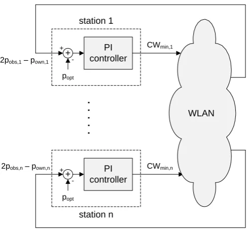
From a control theoretic standpoint, our system can be seen as the composition of the two modules depicted in Fig. 3.1: the controller C(z), which is the adaptive algorithm that controls the WLAN, and the controlled system H(z), which is the WLAN itself.
Following the above, our control system consists of the following two modules:
The PI controller module located at the AP, which takes as input an error signal
e, which is the difference between the observed collision probability in the network
pobs and its desired value as given by Eq. (3.20), and computes theCWmin.
The controlled module, which is the IEEE 802.11 EDCA WLAN system. As speci-fied by the standard, the AP distributes the newCW configuration to the stations with every beacon frame. This configuration is obtained from the CWmin value
given by the controller and Eq. (3.21).
The transfer function of the PI controller is given by [52]
C(z) =Kp+
Ki
z−1 (3.22)
With the above transfer function, at every beacon interval t, the controller will take as input the estimated error signale = pobs−popt and give as output the newCW value
to be used by the contending stations.
CWmin[t] =Kp·e[t] +Ki t−1
X
k=0
e[k] (3.23)
Note that implementing the above equation would be highly inefficient as it would require storing all the error samples from the past. A much more efficient implementation that only requires storing the previous values of CWmin and eis the following:
The estimation of the collision probability over a 100 ms period is performed at the AP as follows. Let R0 be the number of frames received by the AP during this period with the retry bit unset, and R1 be the number of frames received with the retry bit set. Then, if we assume that no frames are discarded due to reaching the retry limit, the collision probability pobs can be computed as
pobs=
R1
R1+R0
(3.25) The above expression is precisely the probability that the first transmission attempt of a frame from any station collides. The reasoning behind the equation is explained as follows. Let us consider that during a given observation period,N packets are transmitted in the WLAN. Assuming that no packets are dropped due to reaching the retry limit,2 all these packets will eventually be successfully transmitted, either with the retry flag set (R1) or unset (R0). Hence a number of packets N =R0+R1 will be observed. Assuming that transmission attempts collide with a constant and independent probability,3 out of these
N packets, in averageN pobswill collide in the first attempt. These packets will eventually
be observed at a later attempt with the retry flag set, which yieldsE(R1) =N pobs. Then,
if we divide the number of packets with the retry flag set by the total number of packets, we obtain (in average) the collision probability,
E
R1
R0+R1
= N pobs
N =pobs (3.26)
which shows that Eq. (3.25) is accurate.
Note that with the above method, the AP can compute the probabilitypobs by simply
analyzing the header of the frames successfully received, which can be easily done with no modifications to the AP’s hardware and driver.
3.1.2.3 Transfer Function Characterization
In order to analyze our system from a control theoretic standpoint, we need to charac-terize the Wireless LAN system with a transfer function that takes CWmin as input and
gives the collision probabilitypobs as output. Since the collision probability is measured
every 100 ms interval, we can safely assume that the obtained measurement corresponds to stationary conditions and therefore the system does not have any memory. With this
2
Note that the assumption that no packets are dropped due to reaching the retry limit is accurate. Indeed, the collision probability in an optimally configured WLAN is very low, which makes the probability of dropping a packet due to reaching the maximum allowed number of retransmissions (typicallyR= 7) negligible.
3
assumption,
pobs = 1−(1−τ)n−1 (3.27)
where τ is a function of CWmin as given by Eq. (3.1),
τ = 2
1 + (CWmin)(1 +pPmi=0−1(2pobs)i)
(3.28)
The above equations give a nonlinear relationship betweenpobs andCWmin. In order
to express this relationship as a transfer function, we linearize this relationship when the system is perturbed around its stable point of operation,4 i.e.,
CWmin=CWmin,opt+δCWmin (3.29)
where CWmin,opt is the CWmin value that yields the optimal collision probability popt
computed in Eq. (3.20).
With the above, the oscillations of the collision probability around its point of opera-tion popt can be approximated by
pobs ≈popt+
∂pobs
∂CWmin
δCWmin (3.30)
The above partial derivative can be computed as
∂pobs
∂CWmin
= ∂pobs
∂τ ∂τ ∂CWmin (3.31) where ∂pobs
∂τ ≈n−1 (3.32)
and
∂τ
∂CWmin
=− 2(1 +pobs Pm−1
i=0 (2pobs)i)
1 +CWmin(1 +pobsPmi=0−1(2pobs)i)
2 (3.33)
Evaluating the partial derivative at the stable point of operationpobs =popt, making
the approximationpopt ≈(n−1)τopt in Eq. (3.19) and using the expression forτopt given
by Eq. (3.1), we obtain
∂pobs
∂CWmin
≈ −poptτopt
1 +popt
Pm−1
i=0 (2popt)i
2 (3.34)
4
C(z)
Σ
z-1
δCWmin
+
δpobs
H(z)
Figure 3.2: Linearized system.
If we now consider the transfer function that allows us to characterize the perturba-tions of pobs around its stable point of operation as a function of the perturbations in
CWmin,
δP(z) =H(z)δCWmin(z) (3.35)
we obtain from Eqs. (3.30) and (3.34) the following expression for the transfer function,
H(z) =−poptτopt
1 +poptPmi=0−1(2popt)i
2 (3.36)
Fig. 3.2 illustrates the above linearized model when working around its stable opera-tion point, with:
(
pobs =popt+δpobs
CWmin=CWmin,opt+δCWmin
(3.37)
Note that, as compared to the model of Fig. 3.1, in Fig. 3.2 only the perturbations around the stable operation point are considered.
3.1.2.4 Controller Configuration
We next address the issue of configuring the PI controller. We observe from Eq. (3.22) that the PI controller depends on the following two parameters to be configured: Kp and
Ki. Our goal in the configuration of these parameters is to find the right tradeoff between
speed of reaction to changes and stability, since bounded oscillation and fast response to disturbances are basic requirements in the design of closed-loop systems. To this aim, we use theZiegler–Nichols rules [55] which have been designed for this purpose. These rules are applied as follows. First, we compute the parameterKu, defined as theKp value that
leads to instability when Ki = 0, and the parameter Ti, defined as the oscillation period
under these conditions. Then,Kp and Ki are configured as follows:
and
Ki =
Kp
0.85Ti
(3.39) In order to compute Ku we proceed as follows. The system is stable as long as the
absolute value of the closed-loop gain is smaller than 1,
|H(z)C(z)|=Kppoptτopt
1 +poptPmi=0−1(2popt)i
2 <1 (3.40)
which yields the following upper bound for Kp,
Kp <
2
poptτopt(1 +poptPim=0−1(2popt)i)
(3.41)
Since the above is a function ofn (note thatτopt depends onn) and we want to find
an upper bound that is independent of n, we proceed as follows. From Eq. (3.19), we observe that τopt is never larger than popt for n > 1 (note that for n = 1 the system is
stable for anyKp). With this observation, we obtain the following constant upper bound
(independent of n):
Kp<
2
p2
opt(1 +poptPmi=0−1(2popt)i)
(3.42)
Following the above, we take Ku as the value where the system may turn unstable
(given by the previous equation),
Ku =
2
p2
opt(1 +poptPmi=0−1(2popt)i)
(3.43)
and set Kp according to Eq. (3.38),
Kp=
0.4·2
popt2 (1 +poptPmi=0−1(2popt)i)
(3.44)
TheKp value that makes the system become unstable yieldsH(z)C(z) =−1. With
such a closed-loop transfer function, a given input value changes its sign at every time slot, yielding an oscillation period of two slots (Ti = 2). Thus, from Eq. (3.39),
Ki =
0.4 0.85p2
opt(1 +poptPmi=0−1(2popt)i)
(3.45)
which completes the configuration of the PI controller. The stability of this configuration is guaranteed by the following theorem.5
Theorem 1. The system is stable with the proposed Kp and Ki configuration.
5
4 4.5 5 5.5 6 6.5 7
5 10 15 20 25 30 35 40
Total throughput (Mbps)
Number of stations
CAC algorithm Static optimal configuration Default EDCA configuration
Figure 3.3: Throughput performance.
3.1.3 Performance Evaluation
In order to evaluate the performance of the proposed algorithm, we performed an ex-haustive set of simulation experiments. For this purpose, we have extended the simulator used in [9, 56]. This is an event-driven simulator written in OMNeT++.6 It implements independently for each station the protocol details and timing of the IEEE 802.11 EDCA MAC, and supports both saturated and non-saturated sources. We integrated into the simulator the proposed approach as well as the centralized solutions of [10,11]. The source code of the simulator and basic use instructions are available online at our OWSiM project page.7
For all tests, we used a payload size of 1000 bytes and the system parameters of the IEEE 802.11b physical layer [3]. For the simulation results, average and 95% confidence interval values are given (note that in many cases confidence intervals are too small to be appreciated in the graphs). Unless otherwise stated, we assume that all stations are saturated.
3.1.3.1 Throughput Performance
The main objective of the proposed algorithm is to maximize the throughput per-formance of the WLAN. To verify if the proposed algorithm meets this objective, we evaluated the total throughput obtained for different numbers of stations n. As bench-marks against which to assess the performance of our approach, we use the static optimal
6
http://www.omnetpp.org 7
configuration given by [26] and the default EDCA configuration given in the IEEE 802.11e standard [6]. Note that the static optimal configuration method requires the knowledge of the number of active stations, which challenges its practical use.
The results of the experiment described above are given in Fig. 3.3. We can observe from the figure that the performance of the proposed algorithm follows very closely the static optimal configuration in terms of total throughput. In contrast, the default configu-ration performs well for a small number of stations but sees its performance substantially degraded as the number of stations increases. From these results, we conclude that the proposed algorithm maximizes the throughput performance.
3.1.3.2 Stability
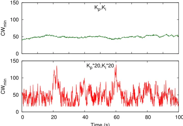
One of the objectives of the configuration of the PI controller presented in Sec. 3.1.2.4 is guaranteeing a stable behavior of the system. In order to assess this objective, we plot in Fig. 3.4 the value of the system’s control signal (CWmin) every beacon interval,
for our {Kp, Ki} setting with n = 20 stations. We can observe that with the proposed
setting,CWmin performs stably with minor deviations around its point of operation. Had
a larger setting for {Kp, Ki} been used to improve the speed of reaction to changes, we
would have experienced the situation of Fig. 3.5. For this case, with values of {Kp, Ki}
20 times larger, the CWmin shows a strong unstable behavior with drastic oscillations.
We conclude that the proposed configuration achieves the objective of guaranteeing a stable behavior.
3.1.3.3 Speed of Reaction to Changes
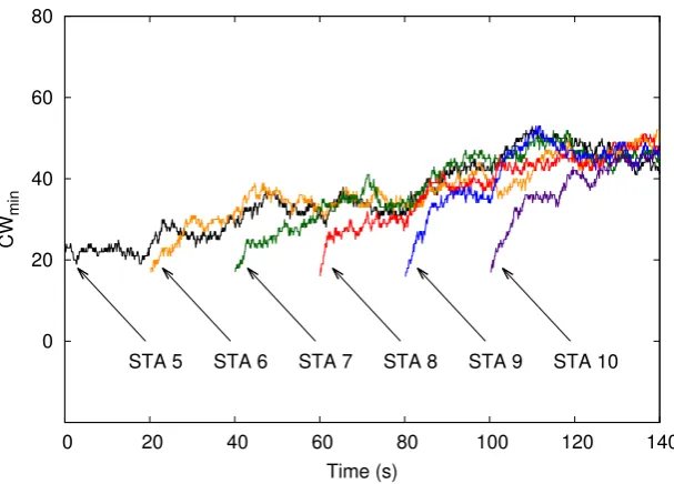
In addition to a stable behavior, we also require the PI controller to quickly react to changes in the WLAN. To assess whether this objective is fulfilled, we ran the following experiment. For a WLAN with 15 saturated stations, att= 80 we added 15 more stations. We plot the behavior of theCWmin for our{Kp, Ki}setting in Fig. 3.6 (label “Kp, Ki”).
The system reacts fast to the changes in the WLAN, as the CWmin reaches the new
value almost immediately. We have already shown in the Sec. 3.1.3.2 that large values for the parameters of the controller lead to unstable behavior. To analyze the impact of small values for these parameters, we plot on the same figure the CWmin evolution for a
{Kp, Ki}setting 20 times smaller (label “Kp/20, Ki/20”). With such setting, the system
reacts too slow to changes of the conditions in the WLAN.
50 100 150 200 250
0 20 40 60 80 100
CW
min
Time (s)
Figure 3.4: Stable configuration.
50 100 150 200 250
0 20 40 60 80 100
CW
min
Time (s)
Figure 3.5: Unstable configuration.
second intervals, for the same experiment of Fig. 3.6. We can see from the figure that the system is able to provide stations with constant throughput (apart from minor oscillations due to the use of CSMA/CA), reacting almost immediately to changes.
3.1.3.4 Non-saturated Stations
0 50 100 150 200 250 300 350
0 100 200 300 400 500
CW
min
Time (s)
Kp,Ki Kp/20,Ki/20
Figure 3.6: Speed of reaction to changes.
0 0.2 0.4 0.6 0.8 1
0 25 50 75 100 125 150
Instantaneous throughput (Mbps)
Time (s)
Figure 3.7: Instantaneous throughput.
4 4.5 5 5.5 6 6.5 7
0 5 10 15 20 25 30 35 40
Total throughput (Mbps)
Number of non-saturated stations CAC algorithm Static optimal configuration
Figure 3.8: Non-saturated stations. of whether they are saturated or not.
We observe from Fig. 3.8 that, with our approach, the total throughput remains ap-proximately constant with values similar to the ones obtained for saturation conditions (Fig. 3.3), independently of the number of non-saturated stations. In contrast, the per-formance of the static optimal configuration decreases substantially as the number of non-saturated stations increases. This is due to the fact that the static optimal configu-ration considers that all stations are continuously sending packets and therefore uses too conservativeCW values.
From the above results, we conclude that our algorithm achieves optimal performance also when non-saturated stations are present in the WLAN, in contrast to the static optimal configuration which sees its performance severely degraded as the number of non-saturated stations increases.
3.1.3.5 Bursty Traffic
In order to understand whether bursty traffic can harm the performance of the pro-posed algorithm, we repeated the experiment reported in Sec. 3.1.3.4 but with the non-saturated stations sending highly bursty traffic instead of CBR. In particular, in our experiment we used ON/OFF sources with exponentially distributed active and idle pe-riods of an average duration of 100 ms each. The results of this experiment are depicted in Fig. 3.9.
4 4.5 5 5.5 6 6.5 7
0 5 10 15 20 25 30 35 40
Total throughput (Mbps)
Number of non-saturated stations CAC algorithm Static optimal configuration
Figure 3.9: Bursty traffic.
1 2 3 4 5 6 7 8
5 10 15 20 25 30 35 40
Total throughput (Mbps)
Number of stations
CAC SCW DTA
Figure 3.10: Comparison against other approaches.
performs the static optimal configuration. We conclude that our approach does not only work well under constant traffic but also under highly variable sources.
3.1.3.6 Comparison Against Other Approaches
1 2 3 4 5 6 7 8
0 2 4 6 8 10
Total throughput (Mbps)
FER (%)
CAC algorithm Static optimal configuration
Figure 3.11: Impact of channel errors.
compare our solution against these centralized mechanisms.
Fig. 3.10 gives the total throughput performance of the different solutions for various numbers of stations. We observe that the proposed algorithm outperforms significantly both SCW and DTA. The reason is that our algorithm is sustained on the analysis of Sec. 3.1.1, which guarantees optimized performance, in contrast to SCW and DTA which are based on heuristics. In particular, SCW uses an algorithm to adjust CWmin that
chooses overly large values, thereby degrading the performance. On the other hand, DTA sets the CWmin as an heuristic function of the number of stations yielding overly small
values, which also results in degraded performance.
3.1.3.7 Impact of Channel Errors
Most of the adaptive mechanisms proposed for IEEE 802.11 WLANs do not consider the impact of channel errors [10–14]. However, channel errors may influence these mecha-nisms since they are wrongly interpreted as collisions, leading to an unnecessary increase of the CW and therefore to a suboptimal configuration.
negligible. Moreover, even for very large error rates (up to 10%) the performance loss is very small. Note that current WLANs use link adaptation mechanisms, which guarantee small error rates by choosing a more robust modulation scheme upon detecting channel quality variations [57]. We conclude that with the proposed scheme errors have a minimal impact on the performance.
With the above, we complete the performance evaluation of the proposedCAC algo-rithm for data traffic. Next, we study the scenario in which stations transmit real-time traffic and extend our algorithm with the goal of improving the delay performance.
3.2
Real-Time Traffic Scenario
The EDCA mechanism is specifically intended to be used for real-time traffic, e.g., video, and, indeed, explicit recommendations for this traffic type are given. However, the use of the fixed set of recommended values for the EDCA parameters results in poor efficiency for most scenarios, as the optimal configuration of the channel access parameters depends on the WLAN conditions. Thus, when the WLAN is heavily loaded, the performance of real-time applications, and in particular the delay experienced by video traffic, is severely degraded. Following this observation, in this section we propose a novel adaptive approach to handle video traffic and optimize its performance. Our proposal embodies an extension to the CAC algorithm presented in Sec. 3.1, and is hereafter referred to asCAC–VI.CAC–VI dynamically adjusts the EDCA configuration of the IEEE 802.11 stations according to the observed conditions in the WLAN, with the goal of minimizing the delay experienced by video traffic. While we tailor our approach specifically to video traffic, we argue that its operation principles can be leveraged to any kind of real-time traffic.
To address the limitations in operating with video traffic, inherent to the standard’s fixed configuration of the MAC parameters, previous works proposed different solutions to improve video performance by adapting the channel access protocol or the behavior of the codecs to the network conditions. These works can be classified as follows:
Cross-layer approaches [58–60]. These approaches classify the frames of a layered-encoded video according to their relevance, and map them to different ACs. A major disadvantage of these works is their complexity, as they involve interactions between the application and the MAC layers, and moreover they either require specific video sources, or modifications of the protocol stack.
behavior of the IEEE 802.11 stations, or replacing the MAC layer ARQ mechanism with an application level scheme, and therefore cannot be implemented with current WLAN cards.
HCCA compliant approaches [64–66]. These approaches are compliant with the IEEE 802.11 specifications, but they are based on the centralized mechanism (namely HCCA), which, unlike the EDCA mechanism, has seen lesser deployments. Moreover, some of them [66] rely on feedback information from the clients, which is typically not available with current device drivers.
EDCA compliant approaches [11,67–70]. These approaches rely on the EDCA stan-dard mechanism and dynamically update the EDCA parameters and/or the video codec behavior based on the observed WLAN conditions. Their major drawback is that they are based on heuristics and lack analytical support, and hence do not guarantee optimized performance.
In contrast to the previous proposals mentioned above, our CAC–VI algorithm has the following key advantages:
1. It is tailored to video applications, as our goal is to optimize the delay performance, which results in a better QoE of the video traffic,
2. It is based on a well established analytical model of the MAC operation [41], which provides the foundations to guarantee optimal performance,
3. It requires no additional signaling and it is fully standard compliant, since the AP drives the WLAN to the optimal point of operation only by observing the behavior of the WLAN,
4. It guarantees simultaneously quick reaction to the changes in the network and stable operation by means of control theory.
5. It supports graceful degradation of video flows by implementing a priority based dropping policy, in line with the efforts of IEEE 802.11TGaa for robust streaming of audio video transport streams [71].
3.2.1 Analytical Model
3.2.1.1 Parameters Configuration
As discussed in Sec. 2.1, the operation of EDCA depends on four configurable param-eters, namely AIF S, T XOP, CWmax and CWmin. Based on the following arguments,
we fix the first three parameters when there is only video traffic present in the WLAN:
AIF S=DIF S. We set this parameter to its minimum possible value, as otherwise additional time is unnecessarily lost after every transmission. Indeed, this parameter aims at providing differentiation between different traffic types and it is not needed when there is only one traffic type present in the WLAN.
CWmax=CWmin. When all parameters are statically set,CWmaxis typically larger
thanCWmin, so that after a collision theCW increases and thus the probability of a
new collision is reduced. However, this is not necessary in our case, as our algorithm dynamically adjustsCWmin, so that the resulting collision probability corresponds
to optimal operation. In addition, if we set CWmax larger thanCWmin, the delay
of the packets that suffer one or more collision drastically grows, which harms jitter performance. Experiments conducted with CWmax= 26·CWmin and withN = 25
stations, report jitter values of up to 15 times larger than for a fixed CW setting, inline with this assumption.
T XOP =T XOPmax. Considering the strict delay requirements of video traffic, it
is desirable that, upon accessing the channel, all the waiting packets in the station’s queue are transmitted in order to minimize their delay. To achieve this, we set the TXOP parameter to its maximum allowed value. Our simulation results included in Sec. 3.2.3.5 confirm that the best performance is achieved with this TXOP setting.
The above settings build on previous works [9, 43] which show that the optimal opera-tion of the WLAN can be achieved without utilizing theAIF SandCWmaxdifferentiation
mechanisms, if an appropriate configuration of the CWmin is employed. Consequently,
we have that the only parameter whose configuration is left open is CWmin. The rest of
this subsection is devoted to the analysis of performance as a function of this parameter, while in the Sec. 3.2.2 we present the adaptive CAC–VI algorithm that sets this param-eter dynamically. To simplify notation, hereafter we refer to the CWmin parameter with
CW.
3.2.1.2 Average Delay
Ȝ Ȝ Ȝ Ȝ Ȝ
ȝ1 ȝ2 ȝ3 ȝ4 ȝn
Figure 3.12: Markov chain model of the WLAN.
The key assumptions behind our analysis are:
Following the findings of [39, 72], we neglect the probability that a station accumu-lates more than one video frame in its transmission queue.
We assume that the aggregate arrivals follow a Poisson process. Considering a sufficiently large number of stations, and given their independence, this assumption is sustained by the Palm-Khintchine Theorem [73].
We consider that access delays are exponentially distributed. This is supported by the observation that delay is mainly dominated by the number of attempts, which follows a geometric distribution, and that such a discrete distribution can be approximated by an exponential one in the continuous domain.
With these assumptions, the WLAN can be analyzed based on the Markov chain of Fig. 3.12, where state i represents the case where there areibacklogged stations with a video frame to transmit,λis the aggregate arrival rate, computed as the individual arrival rate times the number of stations (denoted by n), andµi is the aggregate departure rate
at statei.
To compute the µi’s, we follow the assumption of [41] that the aggregate departure
rate when there are ibacklogged stations can be approximated by the departure rate of the WLAN with isaturated stations, which yields
µi=
rsati
L (3.46)
where L is the average length of a video frame and rsat
i is the total throughput with i
saturated stations. risat is computed following Sec. 3.1.1, but considering the now the length of a video frame instead
rsati = PsL
PsTs+PcTc+PeTe
where Ps, Pc and Pe are the probabilities that a slot time contains a successful
trans-mission, a collision and is empty, respectively, and Ts, Tc and Te are the corresponding
average slot time durations. The probabilities are computed similarly to Eqs. (3.4)–(3.6) of Sec. 3.1.1, but considering only i backlogged stations, and the probability τ that a backlogged station transmits in a randomly chosen slot time, computed with Eq. (3.1) in the case of CWmin =CWmax, i.e.,
τ = 2
CW + 1 (3.48)
The average slot time durations Ts and Tc can be computed from the video frame
length distribution as follows. Let Pl be the probability that the length of a video frame
equals l. Then,
Ts=
X
l
PlTs,l (3.49)
whereTs,l is the duration of a transmission of a video frame of length l. Note that, since
a video frame may be larger than the maximum size of a layer 2 (L2) frame, which we denote by lmax, it may need to be transmitted in several back-to-back L2 frames. Thus,
Ts,l = (N−1)
TP LCP +
H+lmax
C +SIF S+Tack+SIF S
+ TP LCP +
H+l−(N −1)lmax
C +SIF S+Tack+DIF S (3.50)
whereN =dl/lmaxeis the total number of L2 frames in which the video frame is divided,
TP LCP is the Physical Layer Convergence Protocol preamble and header transmission
time,H is the L2 overhead (header and FCS),Tack is the duration of the acknowledgment
frame and C is the channel bit rate.
To computeTc, we neglect the probability that more than two stations collide, similar
to analysis of [9]. With this assumption, Tc can be computed as
Tc=
X
l
X
k
PlPkmax(Tc,l, Tc,k) (3.51)
where Tc,l is the duration of a slot time that contains a collision in which the largest
colliding frame is of size l. Note that in case the video frame is larger than lmax, the
collision is detected after the first L2 frame transmission and no further L2 frames are sent. Thus,
Tc,l=TP LCP +
H+min(l, lmax)
C +EIF S (3.52)
With the above, we can compute the µi values with Eq. (3.46). Once these values
equations we have
Pi =Pi−1
λ µi
(3.53) and applying this recursively
Pi =P0
i Y j=1 λ µj (3.54)
By forcing that allPi’s add to 1, we have
P0 =
1 1 +Pn
i=1 Qi j=1 λ µj (3.55)
From Eqs. (3.54) and (3.55), we can compute all state probabilities Pi, and from the
Pi’s we then calculate the average number of backlogged stations,
nb = n
X
i=1
iPi (3.56)
Finally, by applying Little’s formula [74], we obtain the average delay
D= nb
λ (3.57)
which terminates the delay performance analysis.
3.2.1.3 Optimal Collision Probability
We next compute the optimal collision probability that minimizes the average delay calculated previously. Our optimal collision probability computation is based on the observation that, in order to minimize the average number of backlogged stations (and therefore the delay, since the arrival rates of the Markov chain of Fig. 3.12 are fixed), we need to find the collision probability that maximizes the departure rates µi’s.
We next compute the collision probabilities that maximize the different µi’s. We
first note that in state i = 1, where there is only one backlogged station, the collision probability is necessarily zero, since never more than one station will attempt to transmit in this state.
Fori >1 we proceed as follows. According to Eq. (3.46), maximizingµiis equivalent to
maximizingrisat. According to our previous analysis of Sec. 3.1.1 for saturated conditions, this maximization is achieved when the collision probability has the following approximate value:
pcol = 1−(1−τopt)i−1 = 1− 1−
1
i r
2Te
Tc
!i−1
which can be approximated by
pcol ≈1−e
−q2TcTe
(3.59) Note that with the above approximations pcol does not depend on the number of
back-logge