325 |
P a g e
SHAFT ALIGNMENT IN SHIP
Prasad D. Tupkari
1, Dr. P. K. Sharma
2 1M.tech Research Scholar,
2Guide & Head,
Mechanical Engineering Department, NRIIST, Bhopal M.P. (India)
ABSTRACT
Proper shaft line alignment is one of the most important actions during the design of the propulsion system. Usually,
a beam model of the power transmission system is isolated from the ship hull. Therefore, determining the
correctness of the boundary conditions is one of the most important and difficult issue during the marine shaft line
alignment calculations. In the author’s opinion stiffness and damping characteristics of the journal bearings’ oil
film, ship hull and bearings frame should be taken into account. Ship hull deformations, under different load
conditions and regular sea waves, are also analyzed. The presented numerical analysis method is compared and
verified by measurements on real ships.
Keywords: GAP, Jack up, SAG, Shaft, Ship.
I.INTRODUCTION
1.1Necessity of shafting and its alignment
Shaft alignment and vibration measurements, and modeling, are increasingly becoming an integral part of pro-active cost effective maintenance programs. With an analytical model, and measurements of the alignment and vibration conditions, intelligent decisions with respect repair/maintenance of marine shaft line components can be made.
1.1.1
Propulsion Shaft Alignment
Propeller shaft alignment is different from any other kind of conventional alignment as all shaft bearings (Plummer block, stern tube and bracket bearings) may not be installed in a straight line. Shaft alignment condition of a propulsion shafting may be defined as an arrangement of shaft bearings with offsets relative to a reference line, which under proper operating conditions ensures an optimal load distribution on the bearings.
326 |
P a g e
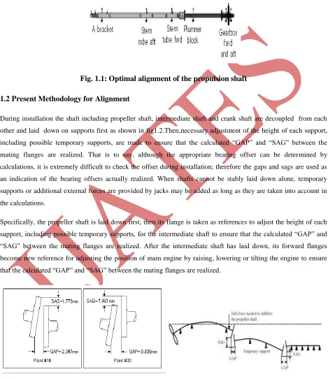
Optimal shaft alignment shown in Figure 1.1 should ensure the followingconditions.
Optimal load distribution on the shaft bearings such that all shaft line bearings are positively loaded and load taken by any one of the bearings does not exceed a specified value depending on the load carrying capability of the bearing.Fig. 1.1: Optimal alignment of the propulsion shaft
1.2 Present Methodology for Alignment
During installation the shaft including propeller shaft, intermediate shaft and crank shaft are decoupled from each other and laid down on supports first as shown in fig1.2.Then,necessary adjustment of the height of each support, including possible temporary supports, are made to ensure that the calculated “GAP” and “SAG” between the
mating flanges are realized. That is to say, although the appropriate bearing offset can be determined by calculations, it is extremely difficult to check the offset during installation; therefore the gaps and sags are used as an indication of the bearing offsets actually realized. When shafts cannot be stably laid down alone, temporary supports or additional external forces are provided by jacks may be added as long as they are taken into account in the calculations.
Specifically, the propeller shaft is laid down first, then its flange is taken as references to adjust the height of each support, including possible temporary supports, for the intermediate shaft to ensure that the calculated “GAP” and “SAG” between the mating flanges are realized. After the intermediate shaft has laid down, its forward flanges
become new reference for adjusting the position of main engine by raising, lowering or tilting the engine to ensure that the calculated “GAP” and “SAG” between the mating flanges are realized.
327 |
P a g e
1.2.1 Need of New Methodology
The present methodology used in new construction ships is installation of shaft during the dry dock phase based on gap/sag methodology. While undertaking these checks, A-bracket and stern tube clearances are monitored to ensure that no bearing is partially loaded or if there are any bottom clearances in any of the bearings. It should be noted that in most of the cases, loads on the stern tube and A-bracket are neither measured, nor taken into account whilst assessing the alignment condition.
The need of the hour is to adopt new technologies to lower the repair time and simplify the repair process. One such technology which has been tried in ships is assessment of shaft alignment using strain gauge technology and assessment with the help of a custom made in-house software MARSHAL.
II. ALIGNMENT MEASUREMENTS
2.1 General
The propulsion shaft alignment is defined as a static condition observed at the bearings supporting the propulsion shafting. To verify acceptability of alignment, it must be confirmed that the following minimum set of parameters are acceptable:
• Bearing reactions
• Bearing vertical offset
• Misalignment angles
• Crankshaft’s web deflections (indirect confirmation of the crankshaft strength)
• Gear misalignment (indirect confirmation of the gear load)
Moreover, we will also provide some requirements on:
• Sag and Gap
• Shaft eccentricity
• Stress measurement in shafting (bending moment, shear force)
Not all of the above measurements are required or conducted on every vessel. Normally, the following measurements are performed:
• Sag and Gap
328 |
P a g e
Crankshaft deflections• Bearing misalignment
• Gear misalignment (where applicable)
2.2 Bearing reaction measurement
Bearing reactions are generally measured utilizing:
• Hydraulic jacks, or
• Strain gauges.
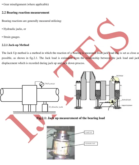
2.2.1 Jack-up Method
The Jack Up method is a method in which the reaction of a bearing is measured from jack load that is set as close as possible, as shown in fig.2.1. The Jack load is estimated from the relationship between the jack load and jack displacement which is recorded during jack up and jack down process.
Fig.2.1: Jack up measurement of the bearing load
329 |
P a g e
Jack-up method is a direct way to check bearing reactions. Due to its simplicity, it is the most widely applied method in the industry. Measurements are conducted by hydraulic jacks which are placed in close proximity to the bearing which reaction is to be measured. It is strongly recommended to use hydraulic jacks in combination with the load cell, as the measurement accuracy will significantly improve. The advantages of the jack-up method are:
• It uses simple measuring equipment such as hydraulic jack and the dial gauge.
• Accuracy is significantly improved in combination with load cell measurement.
• It is the only method that provides reaction load directly.
The disadvantages of the jack-up method are:
• It requires the same preparation time for each repeated measurement.
• Measurement results in wide hysteresis if load cell is not used.
• Installation inaccuracies due to:
Misalignment of the hydraulic jack
Misalignment of the dial gauge
Although it directly records the load, jack-up method does not measure bearing reaction directly, as the jack is
lifting next to the bearing location. This requires correction factors to be applied which introduce some error as well.
The method requires the following equipment: Hydraulic jack (ram)
Load cell Dial gauge
2.3 Theoretical Jack up process
Hydraulic jack should be located as close to the bearing as possible. The foundation on which the jack is placed should be sufficiently stiff. Jack-up measurement may also be used for the shaft run out verification. However, the jack-up method is not very suitable for it since the shaft rotation can be applied only in steps, one angle of rotation at the time.
330 |
P a g e
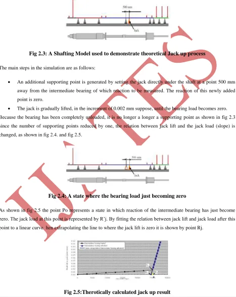
The jack up method can be theoretically demonstrated using a shafting model shown in fig.2.3. The simulation is performed by calculating relationship between the lift up and the reaction at the jack point.Fig 2.3: A Shafting Model used to demonstrate theoretical Jack up process
The main steps in the simulation are as follows:
An additional supporting point is generated by setting the jack directly under the shaft at a point 500 mm
away from the intermediate bearing of which reaction to be measured. The reaction of this newly added point is zero.
The jack is gradually lifted, in the increment of 0.002 mm suppose, until the bearing load becomes zero.
Because the bearing has been completely unloaded, it is no longer a longer a supporting point as shown in fig 2.3 since the number of supporting points reduced by one, the relation between jack lift and the jack load (slope) is changed, as shown in fig 2.4. and fig 2.5.
Fig 2.4: A state where the bearing load just becoming zero
As shown in fig 2.5 the point Po represents a state in which reaction of the intermediate bearing has just become zero. The jack load at this point is represented by R’j. By fitting the relation between jack lift and jack load after this
point to a linear curve hen extrapolating the line to where the jack lift is zero it is shown by point Rj.
331 |
P a g e
III. CONCLUSION
Performing correct shaft alignment saves time and money. Misalignment is the most common cause of machine vibration. Understanding and practicing the fundamentals of shaft alignment is the first step in reducing unnecessary
vibration, reducing maintenance costs, and increasing machine uptime.
Shaft alignment and vibration measurements, and modeling, are increasingly becoming an integral part of pro-active cost effective maintenance programs. With an analytical model, and measurements of the alignment and vibration conditions, intelligent decisions with respect repair/maintenance of marine shaft line components can be made.
The present methodology used in new construction ships is installation of shaft during the dry dock phase based on gap/sag methodology. While undertaking these method it results in difficult as well as imperfect alignment calculations. The need of the hour is to adopt new technologies to lower the repair time and simplify the repair process. One such technology which should be implemented in ships for assessment of shaft alignment using strain gauge technology as it is having following advantages:
The advantages of the strain gauge method are: It can provide information on the bearings not accessible for jack-up measurements, Once the strain gauges are mounted, measurement can be easily repeated within a very short time, It can instantly provide data about vertical load and shaft run out, It can provide simultaneous information on more than one bearing load.
REFERENCES
[1] Bruce Cowper, Al DaCosta, Stephen Bobyn, “Shaft Alignment Using Strain Gauges: CaseStudies” SNAME
Technology Spring.
[2] Cdr M Batra, “ Propulsion Shafting Alignment Using Strain Gauge Technology in New Construction Ship”
IE(I) Journal –MR , Vol 90, JAN 2010
[3] Te-Tan Liao, “Modelling& analysis of laser shaft alignment using 4 x 4 homogeneous co-ordinate
transformation matrix” (2008 Elesvier Ltd)Accepted 6 May 2008
[4] “Guidance Notes on Propulsion shafting Alignment” American Bureau of Shipping incorporated by Act of
Legislature of the State of New York 1862.