604 | P a g e
HOME AUTOMATION USING CLOUD NETWORK &
MOBILE DEVICES
Nilesh N. Mehere
1, Prof. K. Sujatha
2 1,2Department of E & TC, University of Pune, Lonikand, (India)
ABSTRACT
Today, we are entering post-PC era where mobile devices (e.g. iPads, Smartphones and Handheld tablets) are
handling daily tasks that traditional desktop and laptop computers once handled. Several reports show that personal computers are no longer on the leading the edge of computing and the use of mobile devices are
quickly taking over. Accompanying the shift from PCs to multi-touch mobile devices is the use and implementation of Cloud Networking. With the availability of products which integrate mobile devices and
cloud networking rapidly increasing, many users can see how new technology can impact their everyday lives. In this paper we have developed a Home Automation system that employs the integration of multi-touch mobile
devices, cloud networking, wireless communication, and power-line communication to provide the user with remote control of various lights and appliances within their home. This system uses a consolidation of a mobile
phone application, handheld wireless remote, and PC based program to provide a means of user interface to the consumer. The home automation system differs from other systems by allowing the user to operate the
system without the dependency of a mobile carrier or Internet connection via the in-home wireless remote. This system is designed to be low cost and expandable allowing a variety of devices to be controlled.
Keywords:
Mobile cloud computing, mobile services, Java.
1.
I
NTRODUCTIONModern advances in electronics and communications technology have lead to the miniaturization and
improvement of the performance of computers, sensors and networking.
a) An automated device can replace good amount of human working force, moreover humans are more prone to
errors and in intensive conditions the probability of error increases whereas, an automated device can work with
diligence, versatility and with almost zero error.
Home automation can be useful to those who need to access home appliances while away from their home and
can incredibly improve the lives of the disabled. The home automation systems that are available can be divided
into two categorize: locally controlled systems and remotely controlled systems. Locally controlled systems are
the systems that use an in-home controller to achieve home automation. Through such systems the user can
control their home devices within the home through a stationary or wireless interface. Globally-controlled
systems are the systems that use an internet connection. Such systems can be controlled through mobile devices,
personal computer, etc. The problem of home automation system using Bluetooth, GPRS or RFID needs a
605 | P a g e user with limited access as the access area is restricted only within a specific range. Cloud Network and mobile
devices eliminate the need to install and run applications on the customer’s own computers and simplify
maintenance and support. This project integrates the locally and remotely controlled systems with the use of a
Cloud network. Cloud Computing provides access on demand to resources online which requires less
management effort and can be easily provisioned. Your goal is to simulate the usual appearance of papers in
IEEE conference proceedings. For items not addressed in these instructions, please refer to the last issue of your
conference's proceedings for reference or ask your conference Publications Chair for instructions.
The home automation system has been proposed that includes home appliances and devices that are controlled
and maintained for home management [6]. The major task is to improve performance. According to [7] there are
three modules involving sensing unit for monitoring the complex applications. A processing unit, that is
microcontroller and a communication module that uses GPRS modem or cell phone via serial port RS-232. The
SMS is used for status reporting such as power failure. The possible solutions are devised through various
network technologies. Several issues affecting home automation systems such as lack of robustness,
compatibility issue and acceptability among the old and disabled people are discussed [8]. In [9], the spoken
commands are generated and sent in the form of text SMS to the control system and then the microcontroller on
the basis of SMS takes a decision of a particular task.
II. SYSTEM DESIGN
2.1 Cloud Server
Cloud server is used for central storage. Centralization gives cloud service providers complete control over the
versions of the browser-based applications provided to clients, which removes the need for version upgrades or
license management on individual client computing devices. Cloud server contains user databases, glass fish
sever, glassfish is an open source application server which is designed to make the web services accessible in an
efficient and easy way.
Since HASec provides the user the flexibility to choose any type of video-capture devices (e.g., webcams linked
either internally or externally to the server, or IP cameras in the cloud), we had to account for each of their
distinct design details and adapt a solution that would seamlessly integrate them into one cohesive application.
Of the two types, generic webcams were more difficult to implement since they presented a unique challenge to
allow the user to simultaneously view and record live video. We coded a video-capture program in C++ that
responds to RECORD/STOP commands using DirectShow, Microsoft’s multimedia framework and API . It
records video to an AVI file, which is then converted to a playable MP4 file with FFmpeg’s open-source
multimedia converter. If the user is only allowed to view live video without the option to also record, as done by
other applications, the implementation would have been relatively simple. However, our goal was to provide the
user with the flexibility to record the stream while viewing it on the mobile device. The problem we encountered
was that the stream could not be viewed until the recording had stopped. We overcame this challenge by
invoking the open-source VLC media player (from the script for controlling cameras) to access the input stream
via Direct- Show, duplicate it, and process it in the following two ways:
606 | P a g e 2) Transcode to Motion JPEG (so mobile web browsers can natively view the live stream – without any
additional plug-ins) and stream to the web server this also allowed us to avoid splitting or sharing the input
stream. The IP camera, on the other hand, provides a Motion JPEG stream, so we employed VLC media player
to transcode and record the input stream to a MP4 file. To ensure that the PHP script continues to execute before
the C++ and VLC programs exit To display the list of recordings in our application, the PHP script for
recordings reads the contents of the video directory in reverse chronological order, parses the names of MP4
files To ensure that the PHP script continues to execute before the C++ and VLC programs exit (in other words,
without waiting for those applications to terminate), it is executed as a background process. Data Storage and
Retrieval: Recorded videos are stored on the web server with timestamps as the filenames.
2.2 Client
This is the remote user who wants to automate home appliances by using android mobile device or the client pc.
Android is a Linux-based operating system primarily designed for mobile devices such as smart phones and
tablet computers utilizing ARM processors. The iOS device, executing our application, acts as a thin client that
provides the user with a graphical user interface to HASec. We chose the thin client approach because of the
limited computational resources of mobile devices. Since we must have a home computer anyway to
communicate with the device controllers (because of X10’s closed-source SDK), this approach was best suited
for the task at hand. Based on user input, our application is built to communicate with the web server by sending
commands to control and manage devices located around the home. The application is organized into four tabs:
(1) Cameras, (2) Appliances, (3) Recordings, and (4) Options. The buttons on each page are associated with a
Uniform Resource Locator (e.g., a M-JPEG stream, MP4 video, or a server-side script in PHP), and accessed via
HTTP. When the user presses a button, a connection to load the corresponding URL is sent [4], in the form of
http ://( server’s IP address)/ (path to script)? (Command). UIWebView embeds Web such as live streams in the
Cameras tab and a hyperlinked list of captured videos in the Recordings tab. where the user has the option of
viewing one or two cameras. The live streams are loaded from the cloud, either directly from an IP camera or
from the server, and are shown split-screen. The user can then view the cameras individually with the zoom
feature and PAN/TILT them if supported. The user can start or stop video recordings (from one or both cameras)
in the preview and individual pages. Displays an example of appliances integrated with HASec. They can
include lamps and simple (ON/OFF) appliances such as television, computer monitor, alarm clock, and so on.
X10’s Lamp Module allows for changes in light intensity and we provided both a slider and a text field to
control the percentage of brightness. The user can specify the intensity using either one. However, we observed
that this results in many unnecessary commands that can burden the X10 PC Interface and add excessive delay.
Hence, we modified the slider so as to only send the final value. When the user selects the recording to watch (by
tapping on the timestamp), it is played in an appropriate format for the iOS device. Since each video has a URL,
it can be viewed on a web browser as well.
The Options tab gives the user the ability to change settings, including security, the server’s IP address, camera
607 | P a g e automatically recorded and an alert is sent via email, which the homeowner receives along with sound and
vibration (instantly for push email)
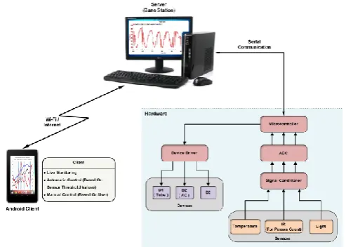
Fig. 1: System architecture of a home automation system using cloud server
2.3 89C51 I Microcontroller
The AT89C51 provides the following standard features: 4K bytes of Flash, 128 bytes of RAM, 32 I/O lines, two
16-bit timer/counters, a five vector two level interrupt architecture, a full duplex serial port.XTAL1 and XTAL2
are the input and output, respectively, of an inverting amplifier which can be configured for use as an on-chip
oscillator ,A quartz crystal oscillator is connected to inputs XTAL1 (pin19) and XTAL2 (pin18) The quartz
crystal oscillator(11.0592MHz) also needs two capacitors of 33 pF value. RESET (Pin 9) pin is an input and is
active high (normally low). Upon applying a high pulse to this pin, the microcontroller will reset and terminate
all activities. The four 8-bit I/O ports P0, P1, P2 and P3 each uses 8 pins. PORT 0 can be used for input or
output, each pin must be connected externally to a 4.7K ohm pull-up resistor .This is due to the fact that P0 is an
open drain, unlike P1, P2, and P3. Open drain is a term used for MOS chips in the same way that open collector
is used for TTL chips.
2.4 Serial Communication
Computers transfer data in two ways:1) Parallel: Often 8 or more lines (wire conductors) are used to transfer
data to a device that is only a few feet away 2) Serial: To transfer to a device located many meters away, the
serial method is used. The data is sent one bit at a time. PC use RS232 interfacing standard for Serial
Communication. An interfacing standard RS232 was set by the Electronics Industries Association (EIA) in
1960.The standard was set long before the advent of the TTL logic family, its input and output voltage levels are
not TTL compatible. In RS232, a 1 is represented by -3 ~ -25 V, while a 0 bit is +3 ~ +25 V, making -3 to +3
undefined. The simplest connection between a PC and microcontroller requires a minimum of three pins, TxD,
RxD, and ground. A line driver such as the MAX232 chip is required to convert RS232 voltage levels to TTL
levels, and vice versa. 8051 has two pins that are used specifically for transferring and receiving data serially.
These two pins are called TxD and RxD and are part of the port 3 group (P3.0 and P3.1). These pins are TTL
608 | P a g e the PC and an 8051 system without any error, we must make sure that the baud rate of 8051 system matches the
baud rate of the PC’s COM port.
2.5 ULN2803 (Darlington Driver)
Featuring continuous load current ratings to 500 mA for each of the drivers, the Series ULN28xx high voltage,
High-current Darlington arrays are ideally suited for interfacing between low-level logic circuitry and multiple
peripheral power loads. Typical loads include relays, solenoids, stepping motors, magnetic print hammers,
multiplexed LED and incandescent displays, and heaters. All devices feature open- collector outputs with
integral clamp diodes.
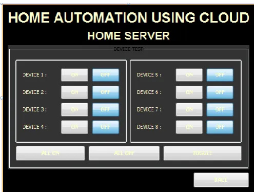
Fig. 3: Screenshots of Home Server Application for Home Automation Using Cloud And
Mobile Devices, (A) User Interface For Monitoring Each Appliance Status.
2.6 ADC (ADC0808) Interfacing
ADCs (analog-to-digital converters) are among the most widely used devices for data acquisition. A physical
quantity, like temperature, Light, humidity, and velocity, etc., is converted to electrical (voltage, current) signals
using a device called a transducer, or sensor. We need an analog-to-digital converter to translate the analog
signals to digital numbers, so microcontroller can read them. ADC808 has 8 analog inputs (IN0 to IN7). It
allows us to monitor up to 8 different sensors using only a single chip. The chip has 8-bit data output. The 8
analog input channels are multiplexed and selected according to three address pins, A, B, and C. Select an
analog channel by providing bits to A, B, and C addresses. Activate the ALE pin; it needs an L-to-H pulse to
latch in the address. Activate SC (start conversion) by an H-to-L pulse to initiate conversion. Monitor EOC (end
of conversion) to see whether conversion is finished. Activate OE (output enable) to read data out of the ADC
chip, An H-to-L pulse to the OE pin will bring digital data out of the chip. 2(-1) to2 (-8)-The digital data output
pins. The system will turn appliances on and off such as: fan and television or any other home appliances. The
system will refresh on the Mobile and PC every time the user chooses an option to control or monitor a specific
609 | P a g e
III. RESULTS
The system will allow the user to control appliances and lights in their home from a Mobile Device and PC from
anywhere in the world through an internet connection. It will also allow the user to control their device units
within their home from home server using GUI. The home server GUI will control over the system; if neither the
Mobile nor PC will be able to control the device units in the home. Another feature provided is auto control.
This feature allows the user to control their home units without any internet connection or without using the
homes server.
IV. CONCLUSIONS
In the home automation system, by integrating multi-touch mobile devices, cloud networking, wireless
communication, and power-line communication, we will be able to design and build a fully functional home
automation system. It will allow the user to control various appliances and lights within their home from any
location in the world through cloud network using 1) mobile devices, 2) PCs, or 3) in-home graphics user
interface (GUI) on their home servers. Using this system as framework, the system can be expanded to include
various other options which could include home security feature such as open-door and motion detection, energy
monitoring, or weather stations.
R
EFERENCES[1] Nicholas D., Darrell B., Somsak S., “Home Automation using Cloud Network and Mobile Devices,” IEEE
Southeastcon 2012, Proceedings of IEEE.
[2] Chan, M., Campo, E., Esteve, D., Fourniols, J.Y., “Smart homes-current features and future perspectives,”
Maturitas, vol. 64, issue 2, pp. 90-97, 2009.
[3] Das, S.R., Chita, S., Peterson, N., Shirazi, B.A., Bhadkamkar, M., “Home automation and security for
mobile devices,” IEEE PERCOM Workshops, pp. 141-146, 2011.
[4] Laur, I., “Microcontroller based home automation system with security,” International Journal of Advanced
Computer Science and Applications, vol. 1, no. 6, pp. 60-65, 2010.
[5] Piyare, R., Tazil, M., “Bluetooth based home automation system using cell phone,” IEEE ISCE, pp.
192-195, 2011.
[6] M. Shell. (2002) IEEEtran homepage on CTAN. [Online]. Available: http://www.ctan.org/ texarchive
/macros/latex/contrib./supported/IEEEtran
[7] FLEXChip Signal Processor (MC68175/D), Motorola, 1996.
[8] PDCA12-70 data sheet,” Opto Speed SA, Mezzovico, Switzerland.
[9] A. Karnik, “Performance of TCP congestion control with rate feedback: TCP/ABR and rate adaptive