571 |
P a g e
MODELLING AND ANALYSIS OF COLD-FORM
BASED COMPOSITE PANEL
Gopika Moorthy
1, Minnu M M
2, Balaji A Raju
3, A Praveen
4, Sailesh K S
5 1, 2Department of Civil Engineering, Amal Jyothi College of Engineering, (India)
3
Engineering Manager, Diagrid Builders and Consulting Engineers (P) Ltd, (India)
4
Department of Civil Engineering, Rajiv Gandhi Institute of Technology, (India)
5
Department of Mechanical Engineering, Saintgits College of Engineering, (India)
ABSTRACT
Composites are ideal materials for the manufacture of prefabricated, portable and modular buildings. The
work deals with the modelling and analysis of a cold form based composite panel using finite element analysis.
Cold-formed steel is the common term for steel products made by rolling or pressing thin gauges of sheet steel
into goods. The proposed panel was modelled and analysed using ANSYS and the simulated results were
tabulated. A concrete panel was also modelled and analysed in the same manner. The scope of the proposed
panel in construction industry was checked by comparison with the modelled concrete panel.
Keywords: Composite panel, Finite element analysis, Mezzanine, Prefabricated, Pre-Engineered
Buildings.
I. INTRODUCTION
Composites are ideal materials for the manufacture of prefabricated, portable and modular buildings. They are
made from two or more constituent materials with significantly different physical or chemical properties. The
composite materials produced by the combination of such constituent materials possess characteristics
different from its individual components. The individual components remain separate and distinct within the
finished structure. The composite structure considered here consists of two external facings bonded to a light
weight and weaker core [1][2]. Such a panel will be light weight with high strength to weight ratio that are
desirable qualities to be used in a pre-engineered building as an alternative for mezzanine floor slabs, partition
walls, roofing purposes etc. In Pre-Engineered Buildings (PEBs), a significant portion except mezzanine floors
and partitions are prefabricated. These works are outsourced to local agencies which may lead to poor quality
work and delay in completion of the work [3]. This work deals with an alternative solution to this limitation in
PEBs. Applications of pre-engineered buildings include factories, commercial showrooms, supermarkets,
office building, warehouse, convention halls, workshops, labour camps, restaurants, aircraft hangars, schools,
almost any one, two or three storeyed building. The key restricting factors in the application of composites are
572 |
P a g e
experts are of the view that with the adoption of advanced technologies and some extent of standardization,
these problems could be easily taken care of.
1.1. Cold-Form Slab Section
Cold form sections are thin sections that are formed in the cold state (i.e. without application of heat) from
steel sheets of uniform thickness. These sections are made to various structural section like C, Z, tube and
various other shapes. Composite structures combine two or more materials in a unit structure to provide
tangible benefits and a versatile solution to suit different applications. A composite system helps to develop
sections that are less in weight, without sacrificing the required capacity. The composite sections for precast
applications are rapidly on an increase with the development of better construction techniques [4][5].
II. MATERIALS
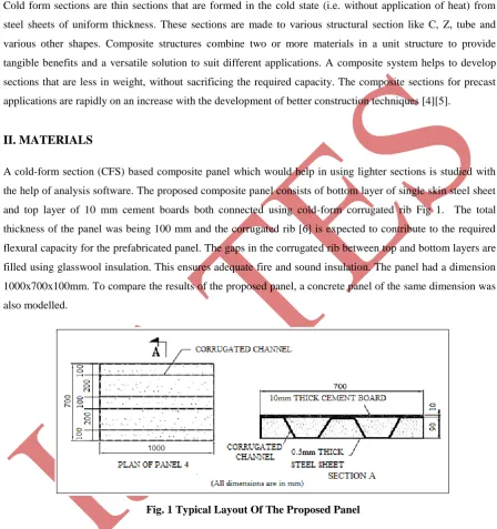
A cold-form section (CFS) based composite panel which would help in using lighter sections is studied with
the help of analysis software. The proposed composite panel consists of bottom layer of single skin steel sheet
and top layer of 10 mm cement boards both connected using cold-form corrugated rib Fig 1. The total
thickness of the panel was being 100 mm and the corrugated rib [6] is expected to contribute to the required
flexural capacity for the prefabricated panel. The gaps in the corrugated rib between top and bottom layers are
filled using glasswool insulation. This ensures adequate fire and sound insulation. The panel had a dimension
1000x700x100mm. To compare the results of the proposed panel, a concrete panel of the same dimension was
also modelled.
Fig. 1 Typical Layout Of The Proposed Panel
The work undertaken here was aimed to investigate the potential application of cold form sections for
designing prefabricated slabs and walls. The preliminary experimental investigation was carried out to
evaluate the capability of prefabricated slabs. It was anticipated that this would help to assess the load carrying
capacity of the designed panel. The deflection analysis of the panel was undertaken using finite element
analysis of the panel.
573 |
P a g e
The structure was analysed using Finite Element Method (FEM). The whole analysis was carried out in
ANSYS 12.1. The structures were modelled first. Each model was then assigned its elemental properties and
meshed. The meshed model was loaded and boundary conditions were applied. Then analysis was carried out
and the desired solutions were obtained.
3.1. Modelling Of The Panels
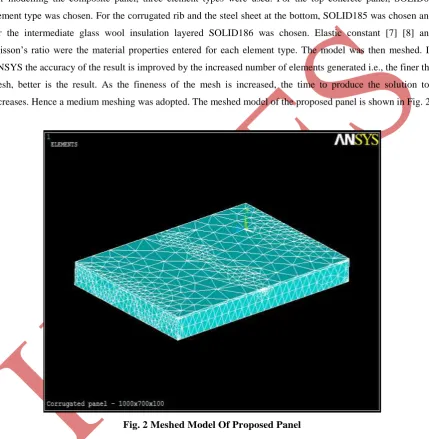
For modelling the composite panel, three element types were used. For the top concrete panel, SOLID65
element type was chosen. For the corrugated rib and the steel sheet at the bottom, SOLID185 was chosen and
for the intermediate glass wool insulation layered SOLID186 was chosen. Elastic constant [7] [8] and
poisson’s ratio were the material properties entered for each element type. The model was then meshed. In
ANSYS the accuracy of the result is improved by the increased number of elements generated i.e., the finer the
mesh, better is the result. As the fineness of the mesh is increased, the time to produce the solution too
increases. Hence a medium meshing was adopted. The meshed model of the proposed panel is shown in Fig. 2.
Fig. 2 Meshed Model Of Proposed Panel
3.2. Loads And Boundary Conditions
The panel was supported to produce a span of 800 mm at the centre i.e., it was provided with two supports at
100mm from each end. Each panel was subjected to load uniformly transferred to the mid-section of the panel.
The loads were provided till the limiting deflection was obtained. The deflection under each load was
recorded.
574 |
P a g e
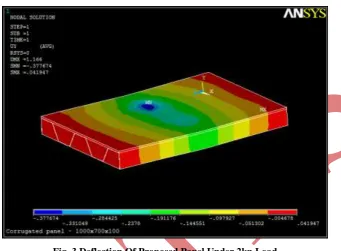
The typical result obtained from the deflection test on the proposed panel specimen is given in Fig. 3. The
maximum deflection obtained under 2kN load is 0.37mm which is represented in the blue coloured region in
the mid span.
Fig. 3 Deflection Of Proposed Panel Under 2kn Load
The deflection of proposed panel and the concrete panel under different loads were compared to understand
the performance of the proposed panel and whether it can be used as an alternative to the concrete panel. Table
1 shows the comparison of deflection of the panels. It may be noted that the deflection of concrete panel is less
than the deflection of proposed panel by 0.2mm under 2kN load, which means the deflection of the proposed
panel is close to that of concrete panel.
Table 1 Comparison Of Deflection
Loads (kN) Deflection (in mm)
Proposed panel Concrete panel
2 0.37 0.35
4 0.75 0.70
6 1.13 1.05
8 1.51 1.40
10 1.82 1.75
12 2.23 2.10
14 2.60 2.45
16 2.97 2.80
575 |
P a g e
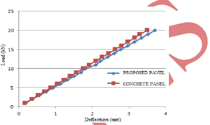
For the light weight prefab panel, serviceability criteria would be dominant than the flexural failure condition
[9]. Deflection limit of span/240 as per AISC 05 (Allowable Stress Design) is considered and load
corresponding at which deflection of span/240 occurs was noted which will be considered as the maximum
load carrying capacity of the panel [10]. The load corresponding to the allowable mid-span deflection, 3.2mm
for the proposed panel was obtained as 16kN while that of the concrete panel was 18kN. The load – deflection
curve of both models have shown identical behavior. Fig. 4 shows the load deflection graphs for proposed
corrugated panel and the concrete panel. It can be seen that the deflection values of both panels are close and
hence the proposed panel may be used as an alternative to concrete panels.
Figure 5.10 Load Vs Deflection Comparison Graph For The Panels
V. CONCLUSION
Composites hold a huge promise for the development of sustainable building practices. The work presented
here was related to the application of the cold form steel sections for the development of pre- fabricated floor
panel. In case of the proposed panel the limiting deflection occurred at 16kN when the same for concrete panel
occurred at 18kN. From IS 875(Part 2)-1987, it can be found that this panel could be used in residential
buildings and office buildings and some areas of storage, industrial and mercantile buildings. The comparison
of the proposed corrugated panel and the presently used concrete panel showed close deflection values. The
feasibility of using such configurations for various construction practices has thus been confirmed. Apart from
structural application, it could find applications in a variety of other fields. Some of these applications are
ships and submarines, aircraft and spacecraft, trucks, rail vehicles, automobiles [11]. As further development,
the panel could be tested experimentally. New modifications can be imparted in this panel to improve its
performance.
576 |
P a g e
[1] Christian Näslund, Osman Ozan Uyanik, Parametric Study of Joint Design in a HSLC Composite Vessel –
Load-carrying Characteristics of Foam Core and Joint Geometry in Sandwich Structures, Proceedings of the
Second International Conference on Light Weight Marine Structures, 2012.
[2] Jagadesh Sunku, Abhaya Shanka, Eco-friendly inorganic bonded sandwich panels (Aerocon panels):
production, properties and application, 11th Int. Inorganic-Bonded Fiber Composites Conference, 2008,
143-150.
[3] Balaji A Raju, Praveen A, Innovative Cold Form Based Composite Section for Enhancing Sustainability in
Built Environment, Proceedings of International Conference on Energy and Environment, ICEE 2013.
[4] Aijaz Ahmad Zende, Kulkarni A V, Aslam Hutagi, Comparative Study of Analysis and Design of
Pre-Engineered-Buildings and Conventional Frames, IOSR Journal of Mechanical and Civil Engineering
(IOSR-JMCE), ISSN : 2278-1684 Volume 5, Issue 1, 2013, 32-43.
[5] Sangeeta Baksi, Suresh Babu M, Srikanth G, Soumitra Biswas, Composites - The Wonder Material, Modern
Plastics & Polymers, 2005.
[6] Tim D Morrison, Innovative Low Cover Bridges Utilizing Deep-Corrugated Steel Plate with Encased
Concrete Composite Ribs, Innovations in Bridge Engineering (B), Annual Conference of the Transportation
Association of Canada, Calgary, Alberta, 2005.
[7] Viggo Tarnow, Measurements of anisotropic sound propagation in glasswool, J. Acoust. Soc. Am. 101,
2000, 2243–2247.
[8] Viggo Tarnow, Dynamic Measurements of Elastic Constants of Glass Wool, Acoustical Society of America,
2005.
[9] Lukaszewska E, Fragiacomo A, Static Performance of Prefabricated Timber-Concrete Composite Systems,
Thesis- Lulea University of Technology, Sweden, 2003.
[10]AISC “American Institute of Steel Construction” Manual of Steel Construction - Allowable Stress Design, 1
East Wacker Drive, Suite 3100, Chicago, Illinois 60601-2001, 2005 Edition.
[11]Madhujit Mukhopadhyay, Mechanics of Composite Materials and Structures, 1st edition, Elsevier science
Ltd, 2004.
Biographical Notes
Ms. Gopika Moorthy is presently pursuing M. Tech. final year in Civil Engineering Department (Specialization
in Structural Engineering & Construction Management) from Amal Jyothi College of Engineering,
Kanjirappally, Kerala, India.
Ms. Minnu M M is working as Assistant Professor in Civil Engineering Department Amal Jyothi College of
Engineering, Kanjirappally, Kerala, India.
Mr. Balaji A Raju is working as Engineering Manager at
Diagrid Builders and Consulting Engineers (P)
Ltd, Kochi, Kerala, India, currently pursuing
PhD from Karpagam University, Tamil Nadu, India.Dr. Praveen A is working as Professor in Civil Engineering Department, R.I.T, Pampady, Kottayam, Kerala,
India.